MD0011-014
Revision A
Page 4 of 15
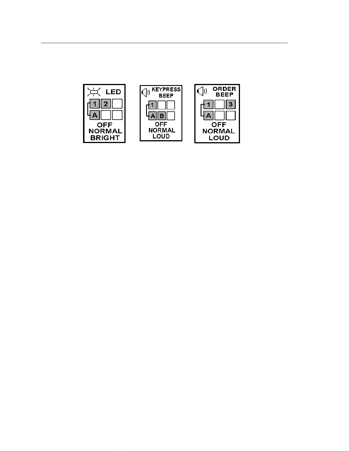
Adjusting the LED and Speaker from the Keypad
The LED brightness and Speaker volume can be adjusted directly from the
keypad at any time. Figure 3, below summaries each adjustment.
Figure 3: Adjusting the LED and Speaker volume from the Keypad
Adjusting the LED Brightness
To adjust the LED brightness, press and hold the [1] and [A] keys, then tap the
[2] key to cycle through the Off, Normal, and Bright settings.
Adjusting the Keypad Speaker
To adjust the volume, press and hold the [1] and [A] keys, then tap the [B] key
to cycle through the Off, Normal, and Loud speaker settings.
Adjusting the Order Notification Beep
To adjust the order notification volume, press and hold the [1] and [A] keys
then tap the [3] key to cycle through the Off, Normal, or Loud settings.
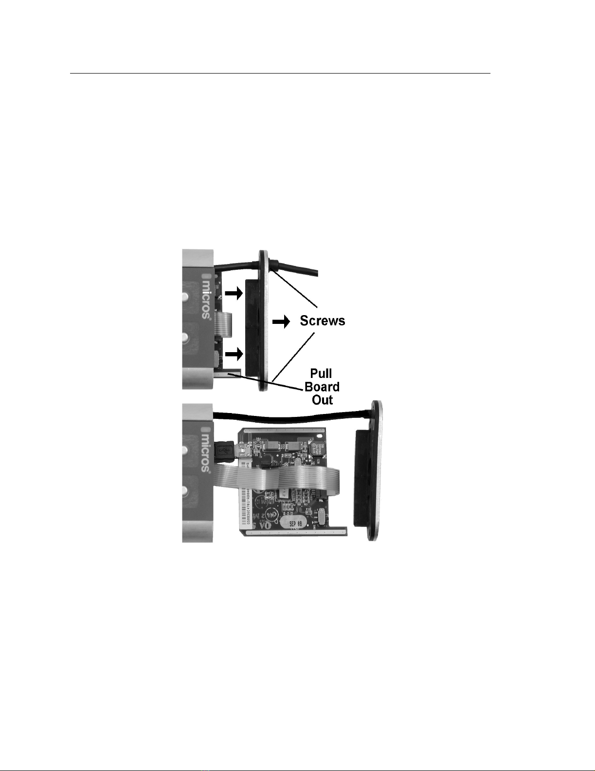
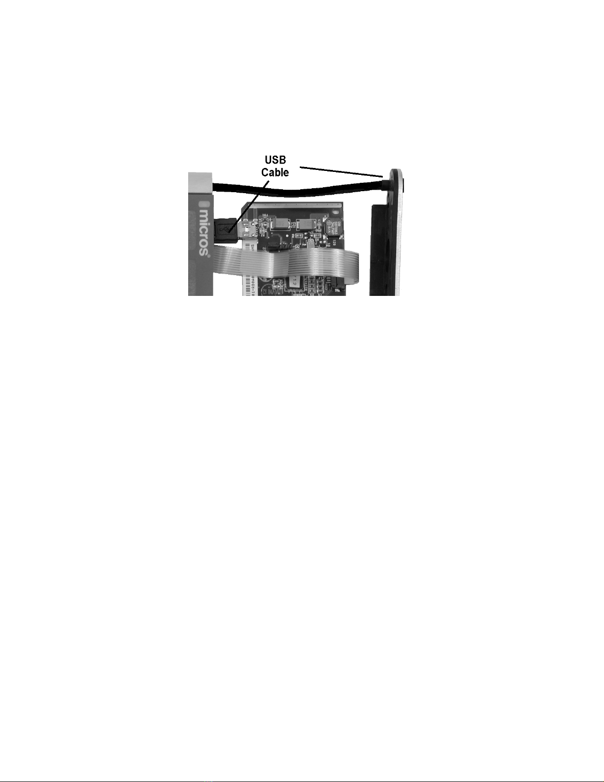
Internal Configuration Switches
The MBB circuit board includes two switches that can be set to send lower
or upper case characters, or reverse the location of the character and
numeric keys for increased mounting flexibility. See Figure 10 for more
information. To open the MBB and access the configuration switches, see
page 8.