SRT SCB-PT User manual
SCB-PT Passive Pneumatic
Controller
User Manual
Version:CV1.0
Soft Robot Tech Co.,Ltd
SCB-PT
Safety notes
Before starting to use this product, please read carefully the safety
precautions and user ’s notices to prevent personal injury or property
damage to oneself and others. This product is equipped with SRT flexible
end fixture, and it should not be used for other purposes.
警告! Warning!
About working environments of the product.
Do not use in environments distributed with corrosive gases,
chemicals, seawater, water and steam.
Do not use in places distributed with explosive gases and dust.
Do not use in places prone to vibration or shock.
Do not use in places around heat sources or radiation heat sources.
If the product is used in places with water drops, oil and welding
sparks, appropriate protecting measures must be taken.

SCB-PT
Contents
1. Product introduction................................................................1
1.1 Packing list.............................................................................. 3
1.2 Panel introduction and size................................................4
1.3 Technical Parameters........................................................... 6
2. Function Description................................................................7
2.1 Display function.....................................................................7
2.2 Manual control.......................................................................8
2.3 Input-output...........................................................................9
2.4 Communication function.................................................. 15
3. Installation.................................................................................16
3.1 Installation fixed.................................................................. 16
3.2 Pneumatic connection....................................................... 16
3.3 Line connection................................................................... 18
4. Installation and use of debugging software.................19
4.1 Software interface............................................................... 19
4.2 Software installation...........................错误!未定义书签。
4.3 Software use......................................................................... 20
5. User information..................................................................... 24

SCB-PT
1
1. Product introduction
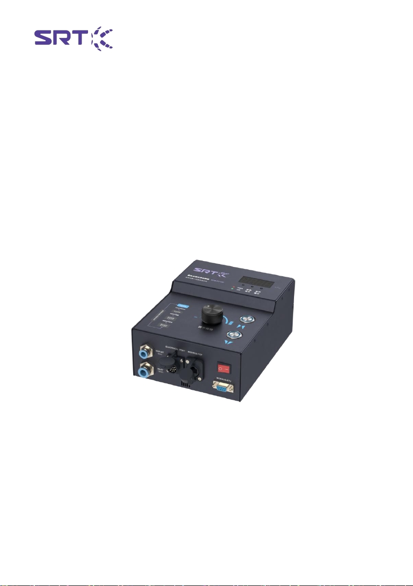
The SCB-PT series passive pneumatic controller is a special pneumatic
drive controller of the SRT flexible end fixture, which can output the
adjustable pressure of 70~100 kPa. Under the trigger of the external
equipment, the flexible end fixture is driven to perform the opening and
grasping action. The positive pressure output corresponds to the
clamping action of the fixture, and the negative pressure output
corresponds to the opening action of the fixture. The controller can be
conveniently equipped with flexible end fixture and other automation
equipment to form a flexible grasping system.
Functional characteristics:
1、Real time status display:
The SCB-PT series controller is equipped with air pressure display and
indicator lamp. The air pressure display can display the real time air
pressure value and set air pressure of the air pressure output port, and
the indicator lamp can display the current working state of the controller.
2、Accurate high speed response
SCB-PT series controllers optimize the control system of the previous
generation of controllers, which can adjust the output pressure more
accurately and quickly, and achieve the set output pressure value in a
short time to meet the requirements of certain working environments.
3、Three pressure regulating modes
SCB-PT series controllers are equipped with adjustment knobs, which
can manually adjust the set pressure of each gear grab and opening,
which is convenient, simple and saves time.
The SCB-PT series controller has eight stalls, which can store up to eight
groups of grasping and opening pressure values, and switch through I /
O signals to deal with complex working conditions.

SCB-PT
2
SCB-PT series controllers support communication voltage regulation.
After the controller connects the communication equipment through the
data line, the set pressure value can be adjusted in real time.
4、Fault alarm function
The SCB-PT controller will detect the output pressure in real time. When
there is air leakage in the end fixture, the indicator light will become red,
and the control system will output signals to facilitate the operator or the
external control system to make judgments and improve the reliability of
the production line.

SCB-PT
3
1.1 Packing list
Name
Amount
Controller
1
User manual
1
DB9 Data Line
1
DB9 Data Line
1
35mm Guide rail buckle
2
Fixed connectors
4
10mm pipe
1
SCB-PT
4
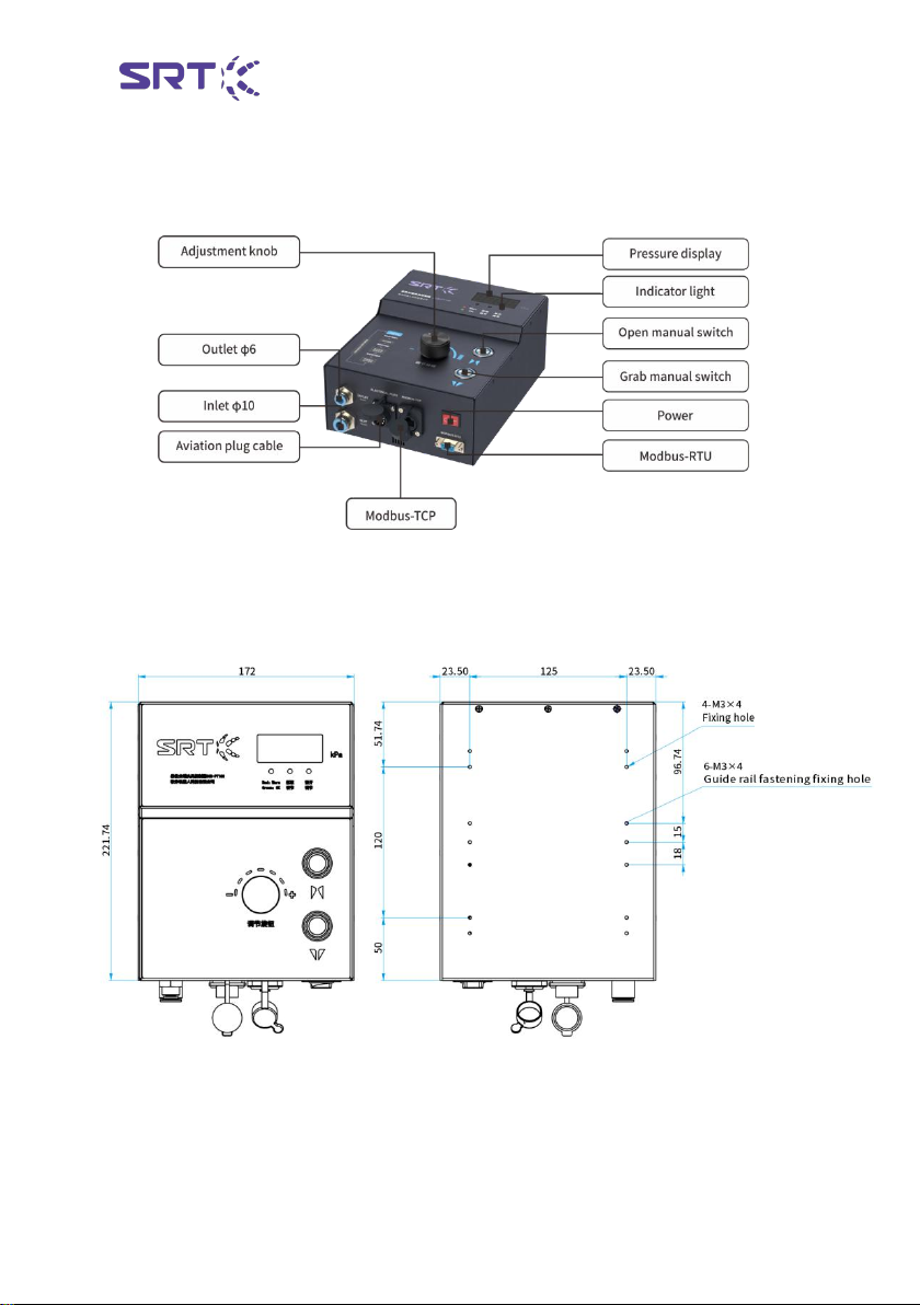
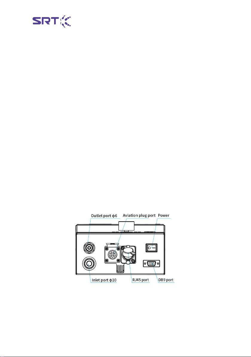
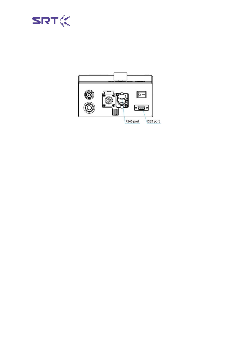
1.2 Panel introduction and size
Unit:mm
SCB-PT
5
Name
Function introduction
Power
Controller power supply switch
Pressure display
Display content
Pilot lamp
Status Display
RJ45 port
MODBUS-TCP protocol
DB9 port
MODBUS-RTU protocol
Manual switch
Manually switch the grabbing/opening state
Aviation plug in port
14 core aviation plug, controller power supply and I / O
Outlet port
Connect the end fixture via φ6 pipe
Intake port
Connect to air source through φ10 pipe

SCB-PT
6
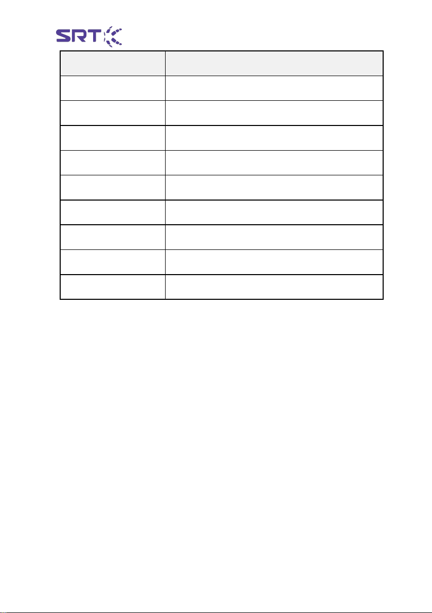
1.3 Technical Parameters
Name
Specification
Dimensions
222*172*96mm
Net weight
3kg
Protection level
IP42
Rated voltage
DC24V±10%
Rated current
2A
Input air pressure range
0.5~0.7MPa clean air source,flow>400L/min
Output pressure range
-80~100kPa
Output positive pressure flow
285L/min
Output negative pressure flow
85L/min
Protective function
Overpressure Overflow, Leakage Alarm, Intake
Detection
Control method
Manual control, I / O signal, communication control
Pressure regulation method
Manual control, I / O signal, communication control
Cooling method
Natural cooling
Working environment
Avoid large amounts of dust, oil and corrosive gases
Ambient humidity
<85%,RH(No dew and beads)
Ambient temperature
-10~50℃(Not frozen)

SCB-PT
7
2. Function Description
2.1 Display function
Display features include pressure display and indicator light
1、Pressure display:
Display the real time output pressure value of the current air outlet;
display the set pressure during grabbing and opening debugging; alarm
information.
2、Indicator light:
Indicator lights are : completion / alarm instructions, grab adjustment
instructions and open adjustment instructions.
Complete / alarm instructions, when the end fixture completes the grab
or open action, the indicator lights green. When the controller detects
that the air inlet interface pressure does not reach the input pressure
range, or the end fixture cannot complete the operation normally, the
indicator light is red.
Grab adjustment indicator light : When the controller enters the manual
modification of the grab pressure setting value, the indicator light is
often bright, and it withdraws from the manual modification of the grab
pressure setting value, and the indicator light is extinguished.
Opening adjustment indicator light : When the controller enters the
manual modification of the opening pressure setting value, the indicator
light is often bright, and exits the manual modification of the opening
pressure setting value, the indicator light is extinguished.

SCB-PT
8
2.2 Manual control
Manual control includes manual switch and adjusting knob, as shown
below :
Manual switch :
It includes grab switch and open switch, which are used to switch the
pressure state and reset controller of the outlet interface. Press the
grab switch alone, the outlet interface will output positive pressure, drive
the end fixture to grab state. Press open switch alone, the outlet
interface will output negative pressure, drive the end fixture to open
state. At the same time press the grab switch and open switch, the
outlet interface output zero pressure, the end fixture to restore the
natural state.
At the same time press the grab switch and open switch, reset the
controller, clear the alarm state.
Adjustment knob :
The adjusting knob is used to manually set the setting pressure for each
gear to grab and open. The operation is as follows :
When the controller is in the initial state, the rotation and short button
adjustment knobs are invalid. After long pressing the adjustment knob
for 3 s, it enters the pressure adjustment state. The first is to grab the
open gear selection interface ( G0 ~ G7 ), the pressure display area shows
SCB-PT
9
the current gear, rotate the adjustment knob to find the gear that needs
to be set, and press the adjustment knob to enter the grasping pressure
setting under the gear.
When entering the grasping pressure setting, the ' grasping adjustment
indicator ' is turned on, the adjustment knob is rotated, and the grasping
pressure setting value is modified. After the setting is completed, the
adjustment knob is pressed to enter the opening pressure setting under
the gear.
When entering the opening pressure setting, the ' grasping adjustment
indicator ' is extinguished, the ' opening adjustment indicator ' is lit, the
adjustment knob is rotated, and the grasping pressure setting value is
modified. After the setting is completed, the adjustment knob is pressed
shortly, and the controller exits the pressure adjustment state.
Note : Initial state means : normal power supply, gas path seal, intake pressure to
meet the requirements, the controller without air pressure output state
2.3 Input-output
Input and output functions include inlet and outlet interface, power
interface and I / O interface.
Inlet port : INLET, suitable for external diameter of 10mm air pipe.
Outlet port : OUTLET, suitable for 6mm outside diameter air pipe.
Elctrical port : ELCTRICAL PORT, including power interface, input
SCB-PT
10
interface and output interface.
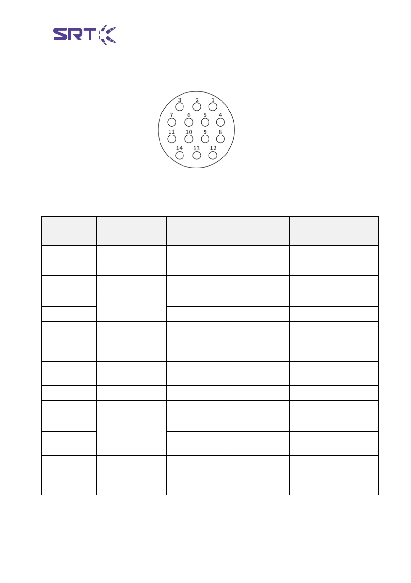
The aviation plug is 14-core cable with the label distribution as follows:
The corresponding relationship between cable and function is as
follows :
Cable color
Name
Aviation
plug cable
Name
Specifications
Red
DC power
supply port
1
24V+
DC 24V electric
support
Black
11
GND
Orange
Gear selection
port
6
IN-SW1
Gear position 1
Yellow
5
IN-SW2
Gear position 2
Brown
9
IN-SW3
Gear position 3
Cyan
Crab trigger port
13
IN-P
Grab trigger input
Green
Open the trigger
port
14
IN-N
Negative pressure
trigger input
Purple
Reset trigger
port
8
IN-RST
Reset trigger input
Grey
12
IN-COM
Input COM
Blue
Signal output
port
2
OUT-ERR
Alarm signal output
Pink
3
OUT-P
Grab complete output
Black and
white
10
OUT-N
Open finish output
White
4
OUT-COM
Output COM
Red and
white
7
NC
Normally closed port

SCB-PT
11
Function Description:
1) DC power supply port : voltage range DC24 ± 10 %, power rating
greater than 50W.
2) Gear selection port
There are eight editable stalls in the PT series controller, and eight sets of
different positive and negative pressure settings can be edited by
manual adjustment or PC software. Usage method : The IN-COM port
of the controller is connected to the output COM of the robot or PLC.
When the logical signals of SW1, SW2 and SW3 ports are 0, the first gear
is triggered. The pressure value of the clamping and opening of the end
fixture driven by the controller will be changed to the set value of the
first gear. When the logical signal of SW1 port is 1, and the logical
signals of SW2 and SW3 ports are 0, the gear 2 is triggered, and the
pressure value of grasping and opening the end fixture driven by the
controller will be changed to the set value of gear 2. File three to eight.
The trigger voltage range is DC24V ± 10 % and the current is more than
100mA. According to the working condition, the appropriate gear
position corresponding to the positive and negative pressure output
value can be selected. Compared with the table below, the I / O signal
triggering the gear position can be input, and the positive and negative
pressure trigger port can be combined to drive the end fixture to
complete the grab or open.

SCB-PT
12
Color/label
Brown/9
Yellow/5
Orange/6
Purple/8
Gear logic
signal port
IN-SW3
IN-SW2
IN-SW1
IN-COM
Gear 1
0
0
0
GND/VCC
Gear 2
0
0
1
GND/VCC
Gear 3
0
1
0
GND/VCC
Gear 4
0
1
1
GND/VCC
Gear 5
1
0
0
GND/VCC
Gear 6
1
0
1
GND/VCC
Gear 7
1
1
0
GND/VCC
Gear 8
1
1
1
GND/VCC
3) Grab, open and reset trigger ports:
The robot or PLC can output positive pressure, negative pressure,
maintenance and zero pressure by using I / O signal to control the outlet
interface of the controller through this port.
Usage : Connect the IN-COM port of the controller to the COM of the
output terminal of the control model of the robot or PLC. When the logic
signal of the IN-P port is 1, the controller performs the positive pressure
output and the end fixture is the grab state. When the IN-N logic
model is 1, the controller performs negative pressure output, and the
end fixture is open. When IN-P and IN-N are both 1, the controller
performs pressure relief action and the flexible gripper is in natural state.
When the reset port logic signal is 1, the controller is reset state, clear
alarm information, etc., and restore to the initial state.
SCB-PT
13
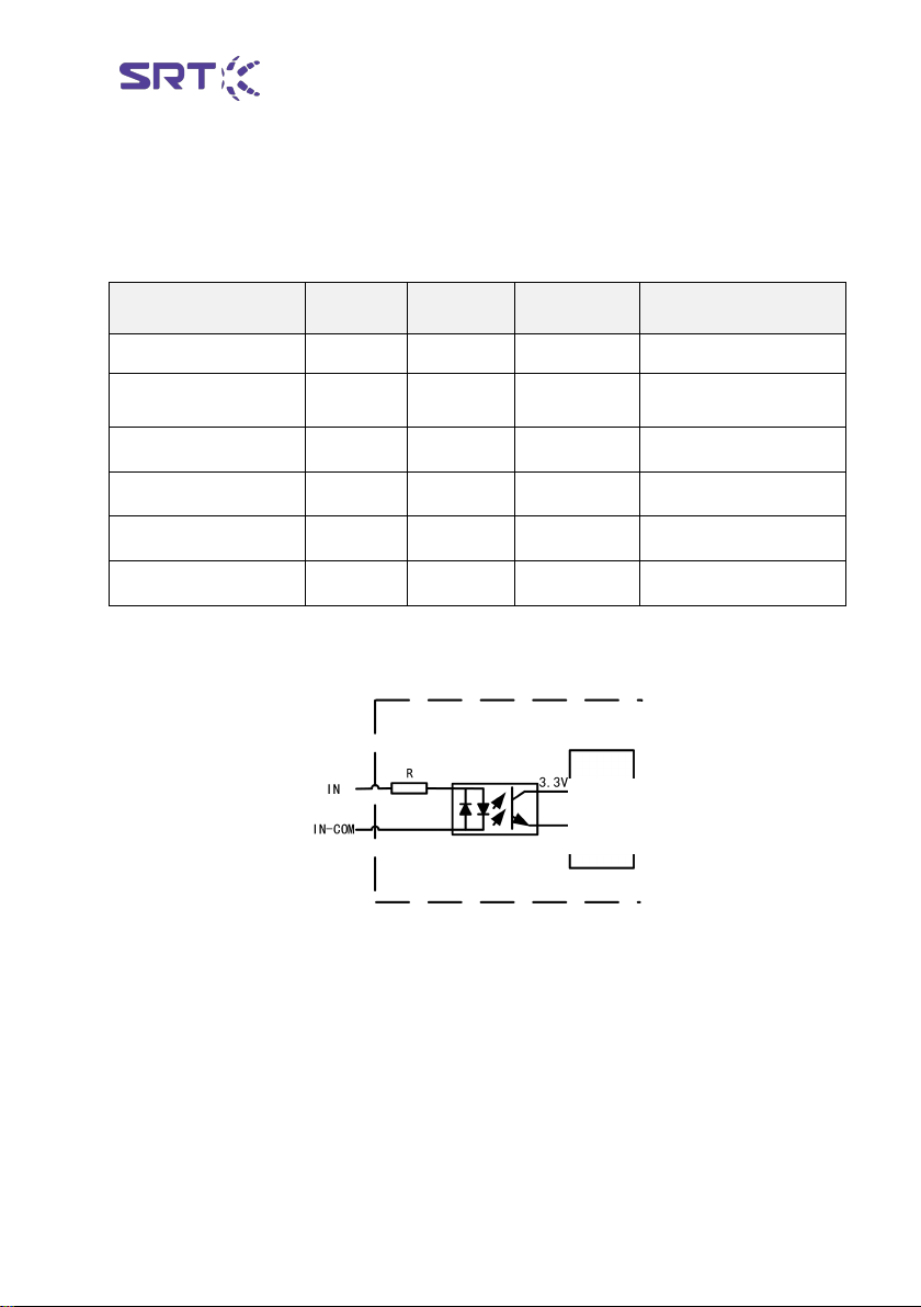
The schematic diagram of the input port is as follows :
The trigger voltage range is DC24V ± 10 % and the current is more than
100mA. The corresponding relationship between I / O signal and action
is as follows :
The schematic diagram of the input port is as follows :
4) Signal output port:
Completed output : When the SCB-PT series controller detects that the
end fixture completes the grasping or opening action, the corresponding
port and OUT-COM will be turned on. Robot or PLC can judge whether
the end fixture completes the grasping or opening action by whether it is
turned on or not.
Alarm output : When the SCB-PT series controller detects the leakage of
Color/label
Cyan/13
Green/14
Purple/8
Gray/12
Gear logic signal port
IN-P
IN-N
IN-RST
IN-COM
Maintain current
state
0
0
0
GND/VCC
Grab action
1
1
0
GND/VCC
Open action
0
1
0
GND/VCC
Pressure relief action
1
1
0
GND/VCC
Reset
0
0
1
GND/VCC
Controller
main circuit
SCB-PT
14
the end fixture, the OUT-ERR port and OUT-COM port will be turned on.
Robot or PLC can judge whether the end fixture has leakage by whether
it
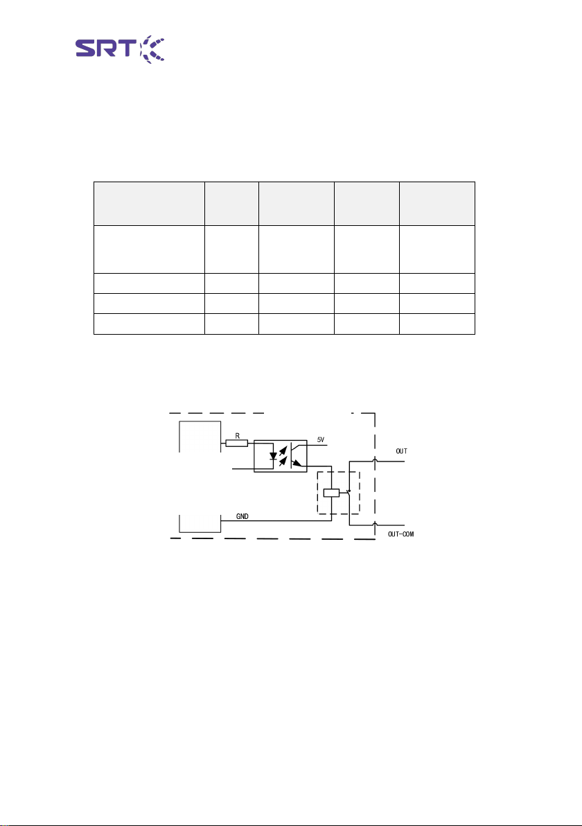
is turned on or not. Ports and functions correspond as follows :
The circuit schematic diagram of the output port is as follows :
Color/label
Pink/3
Black and
white/10
Blue/2
White/4
Gear logic signal
port
OUT-P
OUT-N
OUT-ERR
OUT-COM
Crab complete
1
0
0
GND/VCC
Open complete
0
1
0
GND/VCC
Alarm status
0
0
1
GND/VCC
Controller
main circuit
Internal controller
SCB-PT
15
2.4 Communication function
SCB-PT series controller supports two communication interfaces : RJ45
and DB9. The location is as follows:
Among them : RJ45 interface supports MODBUS-TCP protocol. The
DB9 interface supports MODBUS-RTU protocol. Users can adjust voltage
and set editable files by connecting SRT voltage regulating software
through debugging lines, and can communicate through other control
devices. The communication protocol is referred to the 《SCB-PT series
controller communication protocol description》 document.
SCB-PT
16
3. Installation
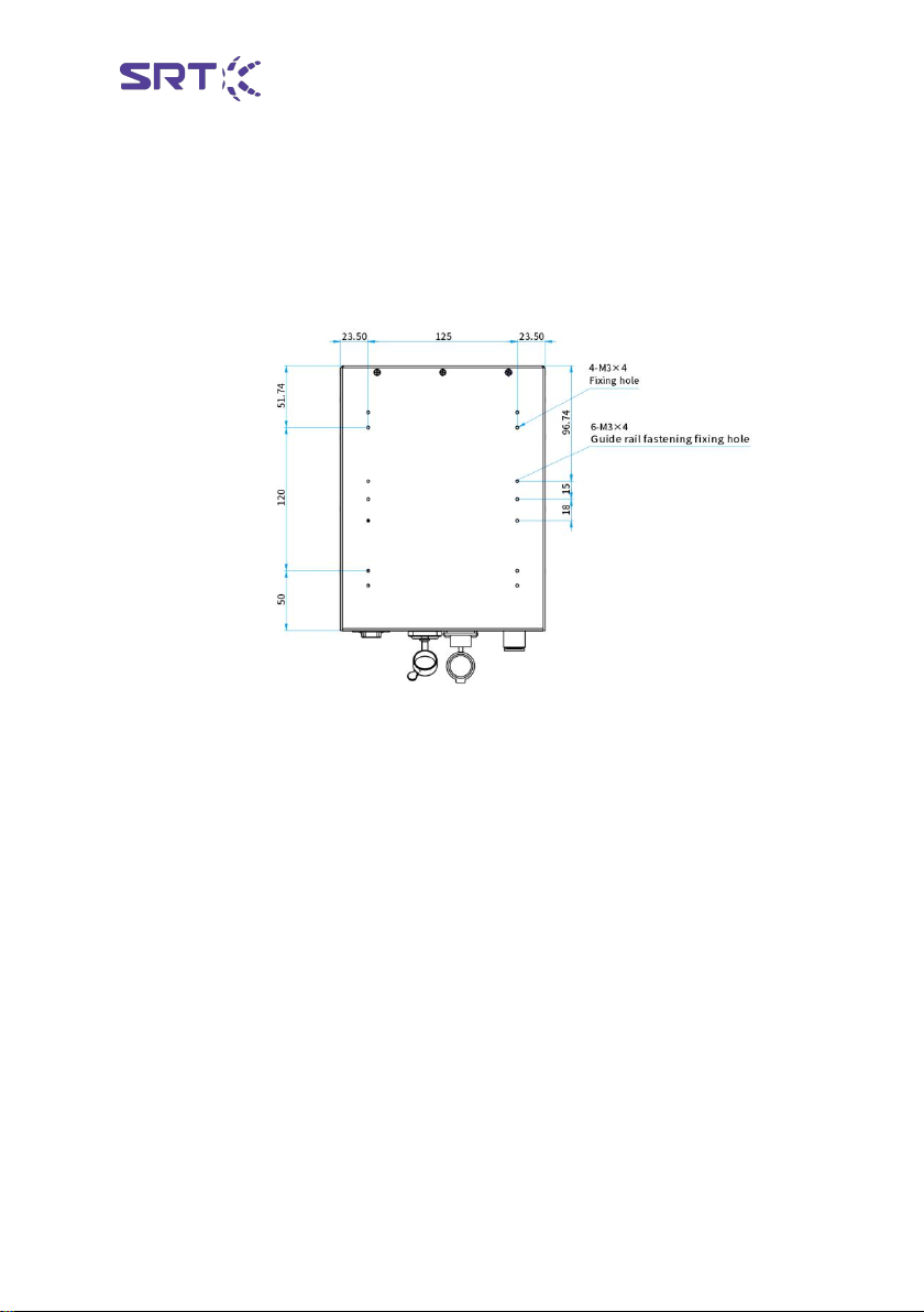
3.1 Installation fixed
The installation hole of SCB-PB series controller is located at the bottom
of the controller, and the size is as follows. Please use M3×4 bolts when
installing.
Installation Precautions :
1、 When the equipment is installed, ensure the equipment is installed
firmly.。
2、When fixing equipment, don 't squeeze equipment into or out of the
air tube or wire。
3、Please do not suspend the controller to a high position to avoid the
controller damage caused by falling.。
4、 Installation of controller grounding in special environment, such as
strong magnetic interference environment。
3.2 Pneumatic connection
Before pneumatic connection, SCB-PT series controller should be in a
safe position, fixed well, to prevent falling, not placed in the sealed box.
SCB-PT
17
Ensure φ 10mm inlet length is sufficient to reach the controller inlet
interface. The φ 6 mm outlet pipe should be connected to the end
fixture after the filter, and the total length is in the range of 3-5 m.
When the gas path is connected, it is ensured that the trachea is
completely inserted into the fast insertion joint. In the insertion process,
there is a clear sense of sudden frustration to prove that the gas path is
connected correctly. After opening the industrial gas source, twisting the
debugging switch, and running three to five times, it is ensured that the
gas path is connected well. If air leakage is found, the gas source and
power supply switch are shut down immediately, and after the air
leakage is eliminated, it can be continued to use.
Notes on Airway Connection:
1、Fully blow or wash the end, oil and dust of the pipe before piping.
2 、 When the controller is connected to the trachea, the bending and
blockage of the trachea are avoided as far as possible, otherwise it is
easy to cause the instability of the pneumatic system of the controller.
3、Do not make mistakes in product inlet and outlet.
4 、 Ensure the air tightness of the product outlet to the end actuator
trachea.
5、Series filter can ensure the service life of the end fixture and pneumatic
controller, and the filter should be between the controller and the end
fixture.
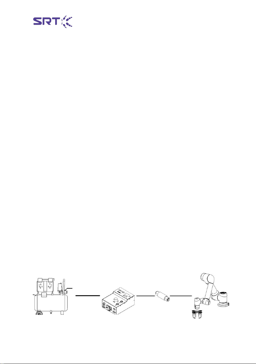
The following diagram is the schematic diagram of gas path connection
for SCB-PT series controllers:
Soft
φ10 pipe
SCB-PB Passive
pneumatic controller
Φ6 pipe
Φ6 pipe
Filter
Clean industrial
gas source
Table of contents
Popular Controllers manuals by other brands

Linak
Linak TD4 user manual

STA-RITE
STA-RITE SR6000S Installation & operation guide

Danfoss
Danfoss AMI 140 Series datasheet

Carrier
Carrier 42EL Aqualia Installation, operation and maintenance instructions

sauter
sauter flexotron 700 user manual

Keating Of Chicago
Keating Of Chicago 8 Product Cooking Controller IM-2000 Operating & programming manual

Valco Cincinnati
Valco Cincinnati MCP-25 user manual

Synapse
Synapse SimplySNAP SS420 Quick install guide

LED Lights Canada
LED Lights Canada SP105E manual

Contrec
Contrec 515 BR03 Operation manual

Hanna Instruments
Hanna Instruments mV 602 Series instruction manual

Sturtevant Richmont
Sturtevant Richmont Global 400mp user manual


