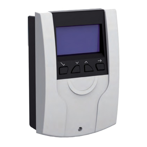
REMKO RR 22.0 User manual

REMKO RR 22.0
Room temperature controller
KWK 130 to 870, KWK 130 to 870 ZW,
KWD 25 to 100 EC, WLT 25 to 85 S,
DKT 21-4 to 71-4
Operation · Technology
Edition GB - N01


Contents
Safety notes 4
Intended use 4
Environmental protection and recycling 5
Guarantee 5
Description 5
Operation 6
Installation Instructions for qualified personnel 7
Installation 7
Adjustable systems and functions 8 - 9
Electrical wiring 10
Electrical drawings 11
Commissioning 11
Technical data 11
Electrical wiring diagram, two-wire system 12 - 19
Electrical wiring diagram, four-wire system 20 - 21
Carefully read this operating manual prior to commissioning/using the units!
This manual is an integral part of the unit and must always be kept in the vicinity
of the installation location or on the unit itself.
This operating manual is a translation of the German original.
Subject to modifications; no liability accepted for errors or misprints!

4
REMKO RR
Carefully read the operating manual
before placing the unit or components
into service for the first time. It provides
useful tips
, notes and hazard
warnings to prevent injury and material
damage. Failure to follow the directions
in this manual can endanger persons,
the environment and the equipment
itself and will void any claims for liability.
■ Keep this manual in the vicinity of the
units or components.
■ Only qualified personnel may set up
and install the units or components.
■ The unit or its components must be
set-up, connected and operated in
accordance with the use and operating
conditions stipulated in this manual
and comply with all applicable local
regulations.
■ Modification of the units and
components supplied by REMKO
is not permitted and can cause
malfunctions.
■ Units and components may not be
operated in areas where there is an
increased risk of damage. Observe the
minimum clearances.
■ The electrical power supply is to be
adapted to the requirements of the
units or components.
■ The operational safety of units or
components is only assured if they are
fully assembled and used as intended.
Safety devices may not be modified or
bypassed.
Safety notes
■ Do not operate units or components
if there are obvious defects or signs of
damage.
■ The units or components must be
kept at an adequate distance from
flammable, explosive, combustible,
abrasive and dirty areas or atmospheres.
■ Installation, repair and maintenance
work may only be carried out
by authorised specialists. Visual
inspections and cleaning can be
performed by the operator as long
as the unit is disconnected from the
power.
■ To preclude any risks to persons
originating from the units or
components, appropriate precautions
must be taken when installing,
repairing, maintaining, cleaning or
working on the units.
Intended use
Depending on the design and
equipment, the components are
intended exclusively for installation in
dry rooms and for controlling cold water
indoor units.
Any different or additional use is
non-intended use. The manufacturer /
supplier assumes no liability for damages
arising from non-intended use. The user
bears the sole risk in such cases.
Intended use also includes working
in accordance with the operating and
installation instructions.

5
Description
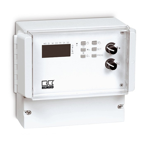
This accessory is an electronic wall-
mounted individual room controller for
temperature regulation of indoor units
for cooling and heating. It automatically
controls the three fan stages and the
opening and closing of the valves for
more convenient temperature control.
The temperature can be measured by
the internal temperature sensor or by
a separate temperature sensor. The inlet
temperature can also be processed. Due
to a large number of program options,
the controller is very versatile and can be
optimally adapted to the system.
The precision room temperature
controller serves for the operation of the
unit series KWK, KWK-ZW, KWD EC,
WLT-S and DKT-4 within closed rooms
from a remote location.
1611381-11611380-1
Guarantee
The warranty conditions are listed in the
"General terms and conditions".
Please contact your direct contractual
partner in the first instance.
Environmental
protection and
recycling
Disposal of packaging
All products are packed for transport
in environmentally friendly materials.
Make a valuable contribution to reducing
waste and sustaining raw materials.
Only dispose of packaging at approved
collection points.
Disposing of the components
The manufacturing process for the
units is subject to continuous quality
control. Only high-grade materials are
processed, the majority of which are
recyclable. Help protect the environment
by only disposing of the components in
accordance with local regulations and
in an environmentally safe manner, e.g.
through authorised disposal and recycling
specialists or at collection points.
■ 1 pc Controller
■ 1 pc Wall bracket
■ 1 pc Fixing material
Scope of delivery
1611380-1
Room temperature probe SA
1611381-1
Inlet temperature probe SM
Accessories

6
REMKO RR
Temperature controller
With the temperature control knob,
the desired setpoint can be set within
the range 5 to 35°C in 1°C steps.
Setting limit
If a limitation of the setting range is to
be implemented on the control knob,
the tabs located in the connection area
within the controller must be inserted
into the corresponding holes and,
if necessary, fixed.
Operation
The remote control is operated using
the relevant switches and temperature
controllers. If necessary, also use the
operating instructions of the unit being
operated.
Mode selector switch
The key is used to switch off "O" of the
controller and to select the operating
mode "Heating " or "Cooling ".
Fan selector switch
The fan level can be changed by
actuating the selector switch. There
are 3 fixed settings ("I" = low,"II" =
medium and "III" = high) as well as an
automatic level ("AUTO"). In "AUTO"
level, a large temperature deviation from
the adjusted set point activates a high
level and in the case of a small deviation,
a low level.
Mode selector switch:
OFF O - Heating - Cooling
Temperature controller:
Adjusting the target temperature
Fanselector switch:
Level 1 - Level 2 - Level 3 -
AUTO
Setting limit

7
Check all plug and terminal
connections to verify that they
are tight and make a permanent
contact. Tighten as required.
CAUTION!
1.Disconnect the power supply.
2.Open the controller cover by lifting off
the rotary knob carefully and pressing
in the lock cautiously.
3.Mount the room temperature
controller on the wall at a height of
approx. 1.5 m above the wall bracket.
Choose an installation location that
is guaranteed good air circulation and
is not affected by any sources of heat
or cold.
4.Make the connections in accordance
with the electrical drawings.
Electric connections must be carried
out as fixed connections in accordance
with the applicable regulations!
5.Check the jumper settings and adjust
them if necessary.
6.Check the terminals are tight.
7. Re-attach the cover.
Installation
Installation instructions
for qualified personnel
■ Check the contents of the packaging
for completeness and check the
unit for visible transport damage.
Immediately notify your contract
partner of any deficiencies.
Installation should only be
performed by authorised
specialists.
NOTE
All electrical installation work
is to be performed by specialist
companies. Disconnect the power
supply when connecting the
electrical terminals.
CAUTION!
Removing the housing cover
Remove the control knob and release
thelocking mechanism
Remove front cover
Wall bracket
2.
1.
60 mm
23 mm
Locking screw

8
REMKO RR
Adjustable systems and
functions
Two-wire system with one valve for
cooling or heating (J1=B):
The controller can be used to control
a system with a heating/cooling valve
in a two-wire system: a system with
a valve-controlled, half-yearly generated
warm medium in winter, e.g. through
a boiler, and half-yearly generated
cold medium in summer, e.g. through
a chiller. But also unswitchable, e.g.
air-water or brine-water heat pumps can
feed a two-wire system.
A heat exchanger in the indoor unit can
then give off the heat or cold.
Only a valve connected to terminal 7-8
regulates the medium-side flow rate in
the heat exchanger of the indoor unit in
both operating modes.
The operating modes can be switched
manually at the controller by means
of the operating mode selector switch
or automatically by means of the inlet
temperature sensor SM.
A heating valve connected to terminal
7-8 and a cooling valve connected to
terminal 8-9 regulate the medium-side
flow rate into the heat exchanger of the
indoor unit in both operating modes.
The operating modes can be switched
manually at the controller by means
of the operating mode selector switch
or automatically by means of the inlet
temperature sensor SM.
Four-wire system with a valve for cooling
and a valve for heating (J1=A):
The controller can be used to control
a system with a cooling valve and
a further heating valve in a four-wire
system: a system with a valve-controlled,
half-yearly generated warm medium
in winter, e.g. through a boiler, and
a second system with half-yearly
generated cold medium in summer,
e.g. through a chiller.
A heat exchanger "cooling" and
a further heat exchanger "heating"
in the indoor unit can then give off the
respective heat or cold.
Two-wire system with a valve for cooling
and an electric heating element for
heating:
The controller can be used to control
a system with an electric heating
element for heating and a valve for
cooling in a two-wire system: an electric,
half-yearly heating element in winter,
and a second system with half-yearly
cold medium in summer, e.g. by a chiller.
A heat exchanger for cooling and
an electrical heating element for heating
in the indoor unit can then give off the
respective heat or cold. An electrical
heating element connected to terminal
7-8 and a cooling valve connected to
terminal 8-9 regulate the control of the
heating element and the medium flow
rate on the medium side in the heat
exchanger of the indoor unit.
The operating modes can be switched
manually at the controller by means
of the operating mode selector switch
or automatically by means of the inlet
temperature sensor SM.
If heating elements are used, it is
necessary to have the fan run on after
the heating element has been switched
off to suit the local conditions (to be
provided by the customer).

9
Valve types
The controller is only designed to control
NC ON/OFF valves:
- an NC valve releases the medium flow
rate into the heat exchanger when
voltage is applied
Setpoint
Hysteresis
Actual value
Valve voltage
Valve opening
0
0
1
1
Mode of operation ON-OFF valve
Inlet temperature sensor SM, alternative
bimetallic thermostat BC (terminal 11-12)
The controller is equipped for use
with an SM inlet temperature sensor
(available as an accessory) or a BC
bimetallic thermostat.
When positioning the inlet temperature
sensor SM on the supply line to
the indoor unit, the controller can
automatically switch to the operating
mode corresponding to the measured
medium temperature (automatic
changeover).
In this case, the heating mode is
activated at a measured temperature
of >30°C and the cooling mode at
a measured temperature of <17°C.
Alternatively, a bimetallic thermostat
BC can be used at the same inlet for
positioning at the heat exchanger, which
releases the fan operation in heating
mode when a minimum temperature
is reached (see chapter "Minimum
temperature medium").
The maximum cable length of 25 m
must not be exceeded.
External room temperature probe SA
(terminal 13-14)
The controller has an internal
temperature probe (J4=A). If the
controller is not going to be located in
the room to be controlled, an optional
room temperature probe accessory can
determine the temperature (J4=B).
The maximum cable length of 25 m
must not be exceeded.
Measuring temperature
The controller measures the temperature
by means of the internal NTC probe
in the controller or on an external
room probe SA, which is available as
an accessory.
If the inlet temperature probe SM or
alternatively a bimetallic thermostat
BC is not used, a jumper between
terminals 11-12 must be provided!
NOTE
Minimum temperature, medium heating
When using a BC bimetallic thermostat,
the fan is only enabled when the bimetal
contact (contact 11-12) is closed. The
use of a inlet temperature probe is then
not possible.
When using an enabling contact
CF and bimetallic thermostat BC,
certain safety restrictions must
be observed. Please refer to the
corresponding chapter.
CAUTION!

10
REMKO RR
Electrical wiring
Mounting the housing cover
3.
2.
1.
1.
General notes
The controller is suitable for controlling
three-stage fan convectors.
The fan stages are controlled by three
potential-free relay outputs at terminals
3 to 5.
The controller is designed for controlling
ON/OFF valves or an electric heating
element. Terminals 7-8 are for heating
output and terminals 8-9 for cooling
output.
External input
Enabling contact CF (terminal L-10)
The controller can be disabled or enabled
by an external potential-free contact.
Operation and temperature control are
not possible when disabled.
As long as the CF input is connected, the
controller cannot be operated.
Additional notes
1. The positioning of the inlet
temperature probe must be selected
in such a way that the temperature
can also be measured when the valve
is inactive.
2. Individual probes may not be used
for several controllers.
3. Only one temperature probe may be
used at the terminals.
4. All probes, bimetallic or enabling
contacts connected must be
insulated accordingly.
5. An all-pole disconnecting main
switch and a fuse must be provided.
6. The connection of all external
contacts, e.g. enabling contacts,
must be galvanically isolated from all
live and earthed parts of the system.
7. If persons can reach the hazardous
areas of external contacts, special
safety measures must be taken (e.g.
safety extra-low voltage).
8. The controller cover may only be
opened in de-energised state.
Configuring jumper
Configuring jumper
J1 Wiring system
four-wire two-wire
J2 Automatic fan operation, every 15 min. for 90 sec.
enabled disabled
J3 Fan function
always active on request
J4 Selection of the temperature sensor
internal (standard)
external (accessory)
A BA B
A BA B
A BA B
A BA B

11
Technical data
Commissioning
We reserve the right to modify the dimensions and design as part of the ongoing technical development process.
Series RR 22.0
Operating mode Precision room temperature controller
for WLT-S/CHP/CHP/CHP-EC/DKT-4
Operating range °C/r.H. 10 to +40/30 to 80% non-condensing
Temperature range for storage purposes
°C/r.H. -10 to +50/20 to 80% non-condensing
Adjustment range °C 5 to +35 (grid = 1)
Control precision/hysteresis °C/K +- 1.5/0.4
Power supply V/Hz 230/1~/50
Enclosure class IP 30
Contact load, max. A 3.0 (Fan)/0.3 (Valve)
Electr. standby losses VA 7.7
Dimensions H/W/D mm 87 / 132 / 38
Weight kg 0.2
Colour Signal white (similar to RAL 9003)
EDP 1611397
1.Switch the unit on using the room
temperature controller.
2.Program the desired functions.
3.Check all functions.
4.Install all removed parts.
5.Familiarise the operator with the
functions.
Electrical drawings
Legend
BC Bimetallic thermostat, optional
(alternative to SM)
CF Enabling contact, optional
M Fan motor
SA Room temp. probe (Accessory 1611380-1)
SM Inlet temp. probe (Accessory 1611381-1)
Fan level 1
Fan level 2
Fan level 3
Control of heating valve
Control of cooling valve
Inlet temperature probe SM
Enabling contact CF
Option
Room temperature probe SA
Bimetallic thermostat BC
Power supply
Room temperature controller RR 22.0
If the inlet temperature probe SM or
alternatively a bimetallic thermostat
BC is not used, a jumper between
terminals 11-12 must be provided!
NOTE
When using an enabling contact
CF and bimetallic thermostat BC,
certain safety restrictions must
be observed. Please refer to the
corresponding chapter.
CAUTION!

12
REMKO RR
Electrical wiring diagram, two-wire system
RR 22.0 with KWD... EC, two-wire system (example)
Technical modifications reserved. Information provided without guarantee. Customer-specific modification possible!
KWD...EC
RR 22.0
Enabling
contact
CF SA
BC SM
Bimetallic
thermostat
(alternative)
Room
temperature
probe
Inlet
temperature
probe
JP4 = B
Valve
assembly
(accessory)

13
RR 22.0
Enabling
contact CF
SA
BC SM
Bimetallic
thermostat
(alternative)
Room
temperature
probe
Inlet
temperature
probe
JP4 = B
RR 22.0 and SR 1 with multiple KWD... EC, two-wire system (example)
Technical modifications reserved. Information provided without guarantee. Customer-specific modification possible!
KWD...EC
Valve assemblies
(accessories)
Further units
SR 1 (Accessory)
KWD...EC

14
REMKO RR
RR 22.0 with WLT... S, two-wire system (example)
Technical modifications reserved. Information provided without guarantee. Customer-specific modification possible!
WLT...S
RR 22.0
Enabling
contact
CF SA
BC SM
Bimetallic
thermostat
(alternative)
Room
temperature probe
Inlet temperature
probe
JP4 = B
Valve
assembly
(Series)

15
RR 22.0 and SR 1 with multiple WLT... S, two-wire system (example)
Technical modifications reserved. Information provided without guarantee. Customer-specific modification possible!
RR 22.0
Enabling
contact
SA
BC SM
Bimetallic
thermostat
(alternative)
Room
temperature
probe
Inlet
temperature
probe
JP4 = B
WLT...S WLT...S
Valve
assembly
(Series)
Valve
assembly
(Series)
Further units
SR 1
CF

16
REMKO RR
RR 22.0 with CHP, two-wire system (example)
Technical modifications reserved. Information provided without guarantee. Customer-specific modification possible!
KWK
RR 22.0
Enabling
contact
CF SA
BC SM
Bimetallic
thermostat
(alternative)
Room
temperature
probe
Inlet
temperature
probe
JP4 = B
Valve assembly
(accessory)

17
RR 22.0 and SR 1 with multiple CHP, two-wire system (example)
Technical modifications reserved. Information provided without guarantee. Customer-specific modification possible!
RR 22.0
Enabling
contact
SA
BC SM
Bimetallic
thermostat
(alternative)
Room
temperature
probe
Inlet
temperature
probe
JP4 = B
Valve assembly
(accessory) Valve assembly
(accessory)
KWK KWK
Further units
SR 1
CF

18
REMKO RR
RR 22.0 with DKT... -4, four-wire system (example)
Technical modifications reserved. Information provided without guarantee. Customer-specific modification possible!
Electrical wiring diagram, four-wire system
DKT...-4
RR 22.0
Enabling
contact
CF SA
BC SM
Bimetallic
thermostat
(alternative)
Room temperature
probe
Inlet
temperature
probe
JP4 = B
Heating valve assembly
(provided
by the customer)
Cooling
(Series)

19
RR 22.0 with CHP, four-wire system (example)
Technical modifications reserved. Information provided without guarantee. Customer-specific modification possible!
RR 22.0
Enabling
contact
CF SA
BC SM
Bimetallic
thermostat
(alternative)
Room
temperature
probe
Inlet
temperature
probe
JP4 = B
Four-wire valve
assembly (accessory)
KWK with HR 6

REMKO INTERNATIONAL
... and also right in your neighbourhood!
Take advantage of our experience and advice
REMKO GmbH & Co. KG
Air conditioning and heating technology
Im Seelenkamp 12 D-32791 Lage
Postfach 1827 D-32777 Lage
Telephone +49 5232 606-0
Fax +49 5232 606-260
E-mail [email protected]
Website www.remko.de
We reserve the right to make technical changes and provide no warranty as to the accuracy of this data!
Table of contents
Other REMKO Controllers manuals
Popular Controllers manuals by other brands

PI
PI E-727 user manual

halstrup-walcher
halstrup-walcher PSD4 Series instruction manual

Panasonic
Panasonic EYFRZ01 operating instructions

Epever
Epever TRACER 6420 quick start guide

ABB
ABB PSTX30 370 Series installation instructions

fluidra
fluidra Astral Pool SLX Light Connect Lite installation instructions