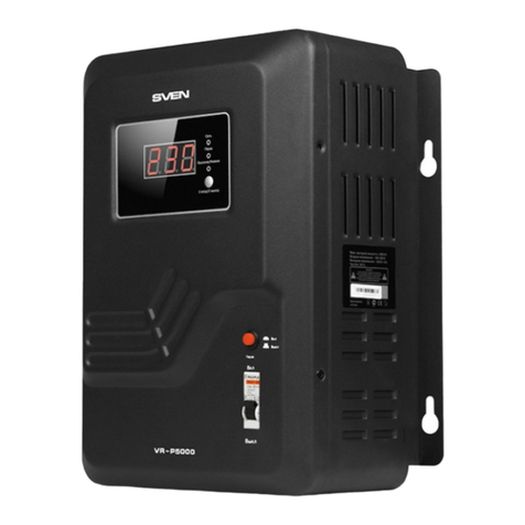
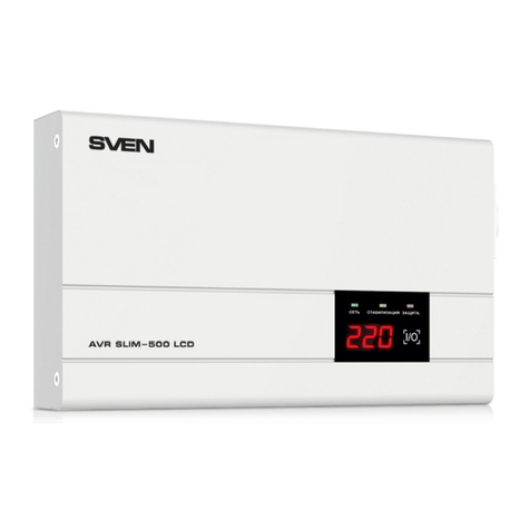
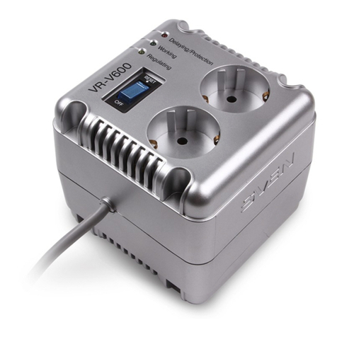
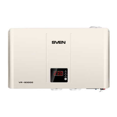
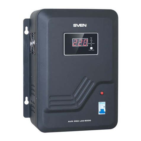
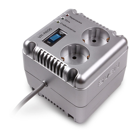
Sven VR-A500 User manual

www.sven.fi
OPERATION
MANUAL
Automatic Voltage Regulator
VR-A500
VR-A1000
VR-A1500
VR-A2000
VR-A3000
VR-A5000
VR-A8000
VR-A10000

2
ENG
Automatic Voltage Regulator
16
17
17
17
19
21
22
CONTENTS
1. BUYER RECOMMENDATIONS ....................................................................
2. PACKAGE CONTENTS...............................................................................
3. SAFETY PRECAUTIONS ............................................................................
4. TECHNICAL DESCRIPTION ........................................................................
5. INSTALLATION AND OPERATION GUIDE .......................................................
6. TROUBLESHOOTING .............................................................................
7. TECHNICAL SPECIFICATIONS ...................................................................
Technical support is on www.sven.fi
Congratulations on your purchase of Sven Automatic Voltage Regulator!
Please read this Operation Manual before using the unit and keep this Operation Manual in a safe
place for future reference.
COPYRIGHT
© 2017. SVEN PTE. LTD. Version 1.0 (V 1.0).
This Manual and information contained in it are copyrighted. All rights reserved.
TRADEMARKS
All trademarks are the property of their legal holders.
NOTICE OF RESPONSIBILITY RESTRICTION
Despite all the efforts to make this Manual most accurate, some discrepancies may occur.
Information in this Manual is given on «As it is» basis. Author and publisher do not bear any liability
to a person or an organization for loss or damages which have arisen from the information,
contained within the given Manual.
1. BUYER RECOMMENDATIONS
• Unpack the device carefully. Make sure there are no accessories left in the box. Check up the
device for damage; if the product was damaged during transportation, address the firm which
carried out the delivery; if the product functions incorrectly, address the dealer at once.
• Shipping and transportation equipment is permitted only in the original container.
• Does not require special conditions for realization.
• Dispose of in accordance with regulations for the disposal of household and computer equip-
ment.

ENG
Operation Manual
3
VR-A500/VR-A1000
VR-A1500/ VR-A2000
VR-A3000/ VR-A5000
VR-A8000/ VR-A10000
2. PACKAGE CONTENTS
• Automatic Voltage Regulator — 1 pc
• Operation Мanual — 1 pc
• Warranty card — 1 pc
3. SAFETY PRECAUTIONS
• When the input voltage is higher than 290V, failure of the AVR is possible.
• Do not operate the AVR in the environment with temperatures other than indicated in Technical
Specifications.
• The case heats up in operation. Operate the AVR in the environment with good air convection
only.
• The socket for connection should be located close to the device and be easily accessible*.
• In case of emergency, switch off the AVR and unplug the power cord* immediately.
• Do not open the device or repair it on your own.
• Do not connect household appliances with power load higher than allowed.
z Connection of electric heating devices is forbidden.
* For models with built-in power cord with plug.
4. TECHNICAL DESCRIPTION
Automatic Voltage Regulators (AVR) are designed to protect your electronic equipment from
unstable mains voltage. Over- and undervoltage and pulse interference prevents electronic
equipment from normal operation and can easily damage it. AVR is designed to protect all types of
TVs, DVD players/recorders, refrigerators, audio and PC equipment and other home electronic
appliances. Its operating principle is based on discrete regulation of input voltage range. AVRs
provide standard power supply to connected load witnin the range of ~230V (-14/+10%) with input
voltage fluctuation within ~140-275 V + 3%. The built-in surge protector provides protection from
pulse interference.
Special features
• Microprocessor control
• Enhanced precision of output voltage regulation
• Protection of consuming appliance against high/low voltage
• Protection of AVR against short circuit and overload
• Thermal protection of autotransformer
• Power supply delay function (6 - 180 sec.) after work resumption
• Digital indicator of input/output voltage on the front panel
• Built-in surge protector
Caution! High voltage inside! To avoid the risk of electric
shock do not open or touch elements inside.

ENG
Automatic Voltage Regulator
4
h
i
j
Fig. 2. VR-A500, VR-A1000 rear panel
a
b
c
e
f
g
d
Fig. 1. VR-A500, VR-A1000 front panel
a
b
c
e
f
g
d
Fig. 3. VR-A1500, VR-A2000 front panel
Control Panels
a Working: operation indicator, glows when the regulator is turned on
b LED-display
c Regulating: stabilized output voltage LED operation indicator
d Protecting: protection indicator
e I/O: input / output voltage display selection button
f Delay: loading delay selection button
g Power: On/Off switch
h Socket (s)
i Input: power cable
j Circuit Breaker: automatic fuse for overload tripping and short circuits
Fig. 4. VR-A1500, VR-A2000 rear panel
h
i
j

ENG
Operation Manual
5
VR-A500/VR-A1000
VR-A1500/ VR-A2000
VR-A3000/ VR-A5000
VR-A8000/ VR-A10000
a
b
c
e
f
g
d
Fig.7. VR-A8000, VR-A10000 rear panel
Fig. 5. VR-A3000, VR-A5000,
VR-A8000, VR-A10000 front panel
Fig. 6. VR-A3000, VR-A5000 front panel
5. INSTALLATION AND OPERATION GUIDE
Attention! Before connecting the regulator, make sure that all consuming devices connected
to it are off, and stabilizer switch g is set to «OFF» position.

ENG
Automatic Voltage Regulator
6
Attention! When choosing an AVR, it is necessary to consider that reduction of input
voltage increases value of input current, which means that maximum power of AVR is
reduced too! Such dependence is shown in the graph (Fig.7).
Note. Keep in mind this correlation. If the condition stated above is not met, warranty
servicing becomes void!
• Before installing the AVR, please make sure that total starting current of all power consumers
is lower than AVR power. Besides, taking into account the starting load and power factor of
consumers, it is necessary to apply power margin factor of 1.2–1.5; for such equipment as air
conditioners, fridges, etc., it should be 1.5–2.
• Connect the equipment to the power outlet (s) of the stabilizer.
• Connect the AVR to the power network of 230 V.
Attention! Do not connect the regulator (VR-A3000, VR-A5000, VR-A8000, VR-A10000) to
a household outlet. Maximum current circuit breakers should not be less than the current
circuit breaker on the front panel of the product.
• Press button g. When the stabilizer turns on green LED «Working» gets activated. The digital LED
display b starts the countdown to actual issue of connected power load, while the red LED
«Protecting» blinks. You can choose delay time of powerload issue by pressing Delay button f on
the front panel. After the pause output voltage value is indicated on the LED display b. By
pressing the «I / O» button select indication of the display input or output voltage to be displayed.
Input voltage is displayed via blinking indication.
• When AVR ups or downs voltage, the input voltage indicator will glow with yellow LED
«Regulating».
• In case of overload or short circuit the thermal fuse is triggered. After fixing the cause of overload
turn on the stabilizer (for low-end models, including protective fuse, pressing the button j on the
rear panel).
• When the stabilizer input voltage is higher than 275 V or below 140 V ± 3% the regulator
disconnects the load. At the same time LED operation indicator displays «H»/«L» sign (high / low
input voltage). On the front panel «Protecting» indicator d lights up.
• In models with forced cooling, fan operates at a temperature of autotransformer around 65 °C.
140 150 160 170 180 187 200 210 220 230 240 250 260 2700
50
25
75
100
100 110 120 13 0
Output power, %
Input
voltage, V
Fig. 7.
ENG
Operation Manual
7
VR-A500/VR-A1000
VR-A1500/ VR-A2000
VR-A3000/ VR-A5000
VR-A8000/ VR-A10000
Problem
The stabilizer does not
work.
Stabilizer turned on.
Indicator «Protecting»
doesn't turn off and there
is no output voltage.
Stabilizer disabled load.
«Protecting» indicator
active. The display shows
«L» or «H».
Stabilizer disabled load.
On the LED displayed
«C».
The stabilizer keeps
clicking. «Regulating»
indicator active.
Cause
1. Switch is not turned on.
2. There is no voltage in the mains
socket.
3. Too much load connected.
Protection fuse triggered.
Failure of the testing scheme.
The AVR is defective.
Input voltage is too high or too
low.
Overheating of the transformer.
The stabilizer is overloaded.
The input voltage is very unstable.
Solution
1. Turn on the stabilizer.
2. Make sure the input voltage
is available.
3. Disconnect part of the load.
Turn on the protective fuse.
Switch the AVR off and on again. If
the problem persists, address a
service center.
When the input voltage reaches
140-275 V ± 3%, the AVR will
resume its operation.
Turn off the AVR. Disconnect part of
the load. After cooling down turn on
the stabilizer.
It is normal. The AVR is regulating
the output voltage.
6. TROUBLESHOOTING
If none of the above can solve the problem, please seek professional advice at your nearest service
center. Never attempt to repair the product yourself.

ENG
Automatic Voltage Regulator
8
424×247×285
317×230×240
230×130×140 255×165×189
≤1200
Maximum output power, W
Fuse, А
AVR type
Input voltage, V
Input frequency, Hz
Output voltage, V
Operating frequency, Hz
Maximum high-frequency interference
energy suppressed, Joule.
Maximum amperage protection, A
Input plug, pc
Output socket, pc
Indicators
Protection
Operating environment
Dimensions, mm
Weight, kg
Relay Type
~140 – 275 ± 3%
50
~230 (-14/+10%)
50
≤350
10000/6500
1 × СЕЕ7/7
Input/output voltage, power on/off, stabilization on/off,
overload protection on/off
high/low voltage, short circuit; overload, high-frequency
interference, built-in thermal protection
0-40°С, 10-90% relative humidity, %
7 32
1 × CEE7/4 2 × CEE7/4
5 20
15 12 50 63
2.3 2.6 3.8 4.0 7.2 9.2 14.9 17.18
≤900 ≤1800 ≤4800 ≤6000
terminals
terminals
≤3000
7. TECHNICAL SPECIFICATIONS
Model
Parameter
Notes:
• Technical specifications given in this table are of supplemental character and can't cause
any claim.
• Technical specifications are subject to change without notice due to improvement of
SVEN production.

Models: VR-A500, VR-A1000, VR-A1500, VR-A2000,
VR-A3000, VR-A5000, VR-A8000, VR-A10000
Импортер в России: ООО «РЕГАРД», 109052,
РФ, г. Москва, ул. Нижегородская, д. 86, корп. Б.
Уполномоченная организация в России: ООО «РТ-Ф»,
105082, г. Москва, ул. Фридриха Энгельса, д. 75, стр. 5.
Условия гарантийного обслуживания смотрите
в гарантийном талоне или на сайте www.sven.fi.
Гарантийный срок: 24 мес.
Срок службы: 5 лет.
Производитель: «СВЕН ПТЕ. Лимитед», 176 Джу Чиат Роуд,
№ 02-02, Сингапур, 427447. Произведено под контролем
«Свен Скандинавия Лимитед», 48310, Финляндия, Котка,
Котолахдентие, 15. Сделано в Китае.
Manufacturer: SVEN PTE. LTD., 176 Joo Chiat Road,
№ 02-02, Singapore, 427447. Produced under the control
of Oy Sven Scandinavia Ltd. 15, Kotolahdentie, Kotka,
Finland, 48310. Made in China.
® Registered Trademark of Oy SVEN
Scandinavia Ltd. Finland.
Automatic Voltage Regulator
VR-A500
VR-A1000
VR-A1500
VR-A2000
VR-A3000
VR-A5000
VR-A8000
VR-A10000
This manual suits for next models
7
Table of contents
Other Sven Controllers manuals

Sven
Sven VR-R600 User manual

Sven
Sven VR-V600 User manual

Sven
Sven AVR SLIM-1000 LCD User manual

Sven
Sven Neo R 500 User manual

Sven
Sven Neo R 500 User manual

Sven
Sven VR-L600 User manual

Sven
Sven AVR-500 LCD User manual

Sven
Sven VR-F1000U User manual

Sven
Sven VR-P5000 User manual

Sven
Sven Neo R 600 User manual