SSINVERTER SSI700 User manual


SSI700 User Manual
www.ssinverter.info
Preface
Thank you for purchasing the SSI700 series AC drive developed by SSINVERTER Co.,
Ltd.
The SSI700 series AC drive is a general-purpose current vector control AC drive. It is an
upgrade product based on SSI700 and can implement the control of asynchronous motor
It increases the user programmable function, back ground monitoring software and
communication bus function . It is used to drive various automation production equipment
involving textile, paper-making, wiredrawing, machine tool, packing, food, fan and pump.
This manual describes the correct use of the SSI700 series AC drive, including selection,
parameter setting, commissioning, maintenance & inspection. Read and understand the
manual before use and forward the manual to the end user.
Notes
• The drawings in the manual are sometimes shown without covers or protective guards.
Remember to install the covers or protective guards as specified first, and then perform
operations in accordance with the instructions.
• The drawings in the manual are shown for description only and may not match the product you
purchased.
• The instructions are subject to change, without notice, due to product upgrade, specification
modification as well as efforts to increase the accuracy and convenience of the manual.
• Contact our agents or customer service center if you have problems during the use.

Safety Information and Precautions

SSI700 User Manual
www.ssinverter.info
Introduction
Compared with SSI700, the SSI900 series AC drive incorporates the following
improvements:
1) Multiple voltage classes
It provides coverage of single-phase 220 V, three-phase 220 V, three-phase 380 V .
2) Control of asynchronous motor
It supports vector control of three-phase AC asynchronous motor.
3) Diversified control modes
It supports control modes, namely, sensorless flux vector control (SFVC) and V/F control.
4) communication protocols
It supports communication via Modbus-RTU .
5) Other new functions
The newly added functions of the SSI700 series AC drive are described as below:
Function Description
Virtual I/O It can implement various simple logic functions.
Rapid current limit It helps to avoid frequent occurrence of overcurrent faults of the
AC drive.
Function Description
Restoring user parameters It allows you to save or restore the parameters set by yourself.
Higher-accuracy AI/AO The AI/AO accuracy can reach almost 20 mv via factory
correction or on-site correction.
Customized parameter
display You can customize the parameters that need to be displayed.
Modified parameter display You can view the modified parameters.
Operation selection at fault
occurrence
You can select the reaction of the AC drive to a fault occurring,
based on the actual need. The reactions are as below:
• Coast to stop
• Decelerate to stop
• Continue to run
You can also select the frequency at which the AC drive
continues to run.
PID parameters switchover Two groups of PID parameters can be switched over via
terminals or can be automatically switched over according to
deviation.
PID feedback loss detection The PID feedback loss value can be set to realize PID
protection.
DI/DO positive or negative
logic You can set the DI/DO positive or negative logic.
DI/DO response delay You can set DI/DO response delay time.
Power dip ride through It ensures that the AC drive continues to run for a short time
when an instantaneous power failure or sudden voltage
reduction occurs.
Timing operation The AC drive supports timing operation for 6500 minutes at
maximum.

SSI700 User Manual
www.ssinverter.info
Product Checking
Upon unpacking, check:
• Whether the nameplate model and AC drive ratings are consistent with your
order. The box contains the AC drive, certificate of conformity, user manual and
warranty card.
• Whether the AC drive is damaged during transportation. If you find any
omission or damage, contact Ssinverter or your supplier immediately.
First-time Use
For the users who use this product for the first time, read the manual carefully. If in doubt
concerning some functions or performances, contact the technical support personnel of
Ssinverter to ensure correct use.
CE Mark
The CE mark on the declares that the AC drive complies with the European low voltage
directive (LVD) and EMC directive.
The SSI700 series AC drive complies with the following LVD and EMC directives and
standards:
The SSI700 series AC drive complies with the requirements of standard IEC/EN 61800-3
on the condition of correct installation and use by following the instructions in chapter 7.
Contents
Preface 1
Introduction 2
Chapter 1 Safety Information and Precautions
1.1 Safety Information
1.2 General Precautions
1
3
Chapter 2 Product Information
2.1 Designation Rules and Nameplate of the SSI700
2.2 Components of the SSI700
2.3 Technical Specifications
2.4 Peripheral Electrical Devices and System Configuration
1
1
1
3
Chapter 3 Mechanical and Electrical Installation
3.1 Mechanical Installation
3.2 Electrical Installation
1
2
Chapter 4 Operation, Display and Application Examples
4.1 Operation Panel
4.2 Viewing and Modifying Function Codes
4.3 Definition and Operation of the Multifunction Key (APP)
4.4 Viewing Status Parameters
4.5 Starting or Stopping the AC Drive
4.6 Setting the Running Frequency
4.7 Setting and Auto-tuning of Motor Parameters
4.8 Use of DI Terminals
4.9 Use of DO Terminals
4.10 Use of AI Terminals
1
2
3
3
6
11
17
19
20
20

SSI700 User Manual
www.ssinverter.info
4.11 Use of AO Terminals
4.12 Use of Serial Communication
4.13 Password Setting
4.14 Parameter Saving and Default Setting Restoring
20
21
21
22
Chapter 5 Function Code Table
5 Standard Function Parameters
1
Chapter 6 Description of Function Codes
Group P0: Basic Parameters
Group P1: Motor 1 Parameters
Group P2: Vector Control Parameters
Group P3: V/F Control Parameters
Group P4: Input Terminals
Group P5: Output Terminals
Group P6: Start/Stop Control
Group P7: Operation Panel and Display
Group P8: Auxiliary Functions
Group P9: Fault and Protection
Group 10: Process Control PID Function
Group 11: Swing Frequency, Fixed Length and Count
Group 12: Multi-Reference and Simple PLC Function
Group 13: Point-point Communication
Group 16: User Password
Group 17: Torque Control and Restricting Parameters
1
9
10
13
15
23
27
32
37
47
53
58
60
63
63
64
Chapter 7 EMC
7.1 Definition of Terms
7.2 Introduction to EMC Standard
7.3 Selection of Peripheral EMC Devices
7.4 Shielded Cable
7.5 Solutions to Common EMC Interference Problems
1
1
2
3
5
Chapter 8 Selection and Dimensions
8.1 Electrical Specifications of the SSI700
8.2 Physical Appearance and Overall Dimensions of the SSI700
8.3 Physical Dimensions of External Operation Panel
8.4 Selection of Braking Resistor
1
1
2
3
Chapter 9 Maintenance and Troubleshooting
9.1 Routine Repair and Maintenance of the SSI700
9.2 Warranty Agreement
9.3 Faults and Solutions
9.4 Common Faults and Solutions
1
2
2
5

Product Information
SSI700 User Manual Product Information
www.ssinverter.info
Chapter 2 Product Information
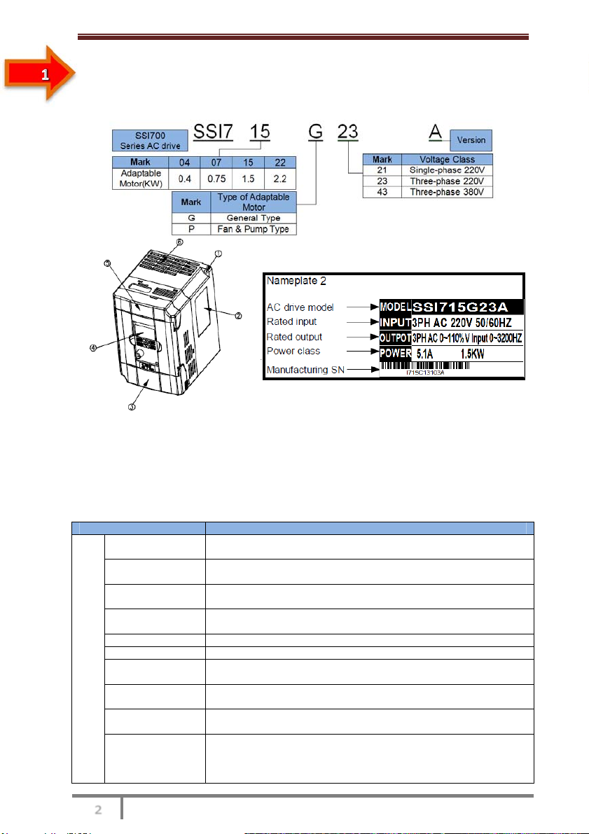
2.1 Designation Rules and Nameplate of the SSI700
Figure 2-1 Designation rules and nameplate of the SSI700
2.2 Components of the SSI700
The SSI700 series AC drives have two housing types, plastic housing according to
different voltage and power classes.
2.3 Technical Specifications
Table 2-1 Technical specifications of the SSI700
Item Specifications
Standard
functions
Maximum
frequency • Vector control: 0–320 Hz
• V/F control: 0–3200 Hz
Carrier frequency 0.5–16 kHz The carrier frequency is automatically adjusted based
on the load features.
Input frequency
resolution Digital setting: 0.01 Hz
Analog setting: maximum frequency x 0.025%
Control mode • Sensorless flux vector control (SFVC)
• Voltage/Frequency (V/F) control
Startup torque • G type: 0.5 Hz/150% (SFVC)
Speed range 1:100 (SFVC)
Speed stability
accuracy • ± 0.5% (SFVC)
Overload capacity • G type: 60s for 150% of the rated current, 3s for 180% of the
rated current
Torque boost • Fixed boost
• Customized boost 0.1%–30.0%
V/F curve
• Straight-line V/F curve
• Multi-point V/F curve
• N-power V/F curve (1.2-power, 1.4-power, 1.6-power, 1.8-power,
square)

SSI700 User Manual Product Information
www.ssinverter.info
Item Specifications
Standard
functions
V/F separation Two types: complete separation; half separation
Ramp mode
• Straight-line ramp
• S-curve ramp
Four groups of acceleration/deceleration time with the range of
0.0–6500.0s
DC braking DC braking frequency: 0.00 Hz to maximum frequency
Braking time: 0.0–36.0s
Braking action current value: 0.0%–100.0%
JOG control JOG frequency range: 0.00–50.00 Hz
JOG acceleration/deceleration time: 0.0–6500.0s
Onboard multiple
preset speeds It implements up to 16 speeds via the simple PLC function or
combination of DI terminal states.
Onboard PID It realizes process-controlled closed loop control system easily.
Individualized
functions
Auto voltage
regulation (AVR) It can keep constant output voltage automatically when the mains
voltage changes.
Overvoltage/
Overcurrent stall
control
The current and voltage are limited automatically during the
running process so as to avoid frequent tripping due to
overvoltage/overcurrent.
Torque limit and
control It can limit the torque automatically and prevent frequent over
current tripping during the running process.
RUN
Running
command source
• Operation panel
• Control terminals
• Serial communication port
You can perform switchover between these sources in various
ways.
Frequency source
There are a total of 10 frequency sources, such as digital
setting, analog voltage setting, analog current setting, pulse
setting and serial communication port setting. You can perform
switchover between these sources in various ways.
Auxiliary
frequency source There are ten auxiliary frequency sources. It can implement fine
tuning of auxiliary frequency and frequency synthesis.
Input terminal
5 digital input (DI) terminals, one of which supports up to 100 kHz
high-speed pulse input
2 analog input (AI) terminals, one of which only supports 0–10 V
voltage input and the other supports 0–10 V voltage input or 4–20
mA current input.
Output terminal
1 high-speed pulse output terminal (open-collector) that supports
0–100 kHz square wave signal output
1 digital output (DO) terminal
1 relay output terminal
1 analog output (AO) terminal that supports 0–20 mA current
output or 0–10 V voltage output
Display and
operation
LED display It displays the parameters.
Key locking and
function selection It can lock the keys partially or completely and define the
function range of some keys so as to prevent mis-function.
Protection mode
Motor short-circuit detection at power-on, output phase loss
protection, overcurrent protection, overvoltage protection,
undervoltage protection, overheat protection and overload
protection
Enironment
Installation location: Indoor, free from direct sunlight, dust, corrosive gas, combustible
gas, oil smoke, vapour, drip or salt.
Altitude: Lower than 1000 m
Ambient temperature: -10°C to +40°C (de-rated if the ambient temperature is between
40°C and 50°C)
Humidity: Less than 95%RH, without condensing
Vibration: Less than 5.9 m/s2 (0.6 g)
Storage temperature: -20°C to +60°C
IP level: IP20
Pollution degree: PD2
Power distribution System: TN , TT
SSI700 User Manual Product Information
www.ssinverter.info
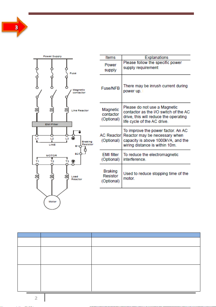
2.4 Peripheral Electrical Devices and System Configuration
When the SSI700 is used to control the synchronous or asynchronous motor, forming a
control system, it is necessary to install various electrical devices on the input and output
sides of the AC drive to ensure the system safety and stability.
Figure 2-2 System configuration of three-phase 220 V/380 V voltage class, 2.2 Kw and
above
2.4.1 Description of Peripheral Electrical Devices
Table 2-2 Description of peripheral electrical devices
Part Mounting Location Function Description
MCCB Power receiving side Interrupt the power supply when overcurrent occurs on
down stream devices
Contactor Between MCCB and
AC drive input side
Start and stop the AC drive.
Do not start and stop the AC drive frequently by switching
the contactor on and off (less than twice per minute) nor use
it to directly start the AC drive.
AC input
reactor AC drive input side
• Improve the power factor of the input side.
• Eliminate the higher harmonics of the input side effectively
and prevent other devices from being damaged due to
distortion of the voltage waveform.
• Eliminate the input current unbalance due to unbalance
between the power phases.

SSI700 User Manual Product Information
www.ssinverter.info
Part Mounting Location Function Description
EMC
Input filter AC drive input side
• Reduce the external conduction and radiation interference
of the AC drive.
• Decrease the conduction interference flowing from the
power end to the AC drive and improve the anti interference
capacity of the AC drive.
AC output
reactor
Between AC drive output
side and the motor, close
to the AC drive
The output side of the AC drive generally has much higher
harmonics. When the motor is far from the AC drive, there is
much distributed capacitance in the circuit and certain
harmonics may cause resonance in the circuit, bringing
about the following two impacts:
• Degrade the motor insulation performance and damage
the motor in the long run.
• Generate large leakage current and cause frequent AC
drive protection trips.
If the distance between the AC drive and the motor is
greater than 50 m, install an AC output reactor.
1) Do not install the capacitor or surge suppressor on the output side of the AC drive.
Otherwise, it may cause faults to the AC drive or damage to the capacitor and surge
suppressor.
2) Inputs/Outputs (main circuit) of the AC drive contain harmonics, which may interfere
with the communication device connected to the AC drive. Therefore, install an anti-
interference filter to minimize the interference.
3) For more details on peripheral devices, refer to related selection manual.
2.4.2 Description of Optional Parts
The optional parts include braking unit of different functions and external operation panel,
etc. If any optional part is required, specify it in your order.
Table 2-3 Optional parts of the SSI700
Name Model Function Remark
Internal
braking unit
AC drive
model
followed
The models of single-phase
(0.4–2.2 kW) and three-phase
(0.75–15 kW) are installed with the
internal braking unit as standard
configuration.
Internal braking unit.
External LED
operation
panel panel It supports LED display and operations. It applies to the SSI700
series AC drives.

Mechanical and Electrical Installation

SSI700 User Manual Mechanical and Electrical Installation
www.ssinverter.info
Chapter 3 Mechanical and Electrical Installation
3.1 Mechanical Installation
3.1.1 Installation Environment Requirements
Item Requirements
Ambient temperature -10°C to +50°C
Heat dissipation
Install the AC drive on the surface of an incombustible object, and
ensure that there is sufficient space around for heat dissipation.
Install the AC drive vertically on the support using screws.
Mounting location
Free from direct sunlight, high humidity and condensation
Free from corrosive, explosive and combustible gas
Free from oil dirt, dust and metal powder
Vibration Less than 0.6 g
Far away from the punching machine or the like
Protective enclosure
The SSI700 series AC drives of plastic housing are the whole unit
built-in products operated through remote control and need to be
installed in the final system.The final system must have the required
fireproof cover, electrical protective cover and mechanical protective
cover, and satisfy the regional laws & regulations and related IEC
requirements.
3.1.2 Installation Clearance Requirements
The clearance that needs to be reserved varies with the power class of the SSI700, as
shown in the following figure.
Figure 3-1 Clearance around the SSI700 for installation
The SSI700 series AC drive dissipates heat from the bottom to the top. When multiple AC
drives are required to work together, install them side by side.
For application installing multiple AC drives, if one row of AC drives need to be installed
above another row, install an insulation guide plate to prevent AC drives in the lower row
from heating those in the upper row and causing faults.

SSI700 User Manual Mechanical and Electrical Installation
www.ssinverter.info
■ Installation Precautions
1) Reserve the installation clearances as specified in Figure 3-1 to ensure sufficient space
for heat dissipation. Take heat dissipation of other parts in the cabinet into consideration.
2) Install the AC drives upright to facilitate heat dissipation. If multiple AC drives are
installed in the cabinet, install them side by side. If one row of AC drives need to be
installed above another row, install an insulation guide plate .
3) Use incombustible hanging bracket.
3.2 Electrical Installation
3.2.1 Description of Main Circuit Terminals
■ Description of Main Circuit Terminals of Three-phase AC drive

SSI700 User Manual Mechanical and Electrical Installation
www.ssinverter.info
Table 3-1 Description of main circuit terminals of three-phase AC drive
Terminal Name Description
R, S , T Three-phase power supply
input terminals
Connect to the single-phase 220 VAC power
supply.
B1, B2 Connecting terminals of
braking resistor
Connect to the braking resistor for the AC drive of
2.2 kW and below (220 V) and 7.5 kW and below
(other voltage classes).
U, V, W AC drive output terminals Connect to a three-phase motor.
Grounding terminal Must be grounded.
3.2.2 Wiring of AC Drive Main Circuit
■ Precautions on the Wiring
1) Power input terminals R, S, T
– The cable connection on the input side of the AC drive has no phase sequence
requirement.
– The specification and installation method of external power cables must comply with the
local safety regulations and related IEC standards.
– Use copper conductors of a proper size as power cables according to the recommended
values in section 8.3.
2) Braking resistor connecting terminals B1 , B2
– The connecting terminals of the braking resistor are effective only for the AC configured
with the built-in braking unit.
– The cable length of the braking resistor shall be less than 5 m. Otherwise, it may
damage the AC drive.
3) AC drive output terminals U, V, W
– The specification and installation method of external power cables must comply with the
local safety regulations and related IEC standards.
– Use copper conductors of a proper size as power cables according to the recommended
values in section 8.3.
– The capacitor or surge absorber cannot be connected to the output side of the AC drive.
Otherwise, it may cause frequent AC drive fault or even damage the AC drive.
– If the motor cable is too long, electrical resonance will be generated due to the impact of
distributed capacitance. This will damage the motor insulation or generate higher leakage
current, causing the AC drive to trip in overcurrent protection. If the motor cable is greater
than 100 m long, an AC output reactor must be installed close to the AC drive.
4) Terminal PE
– This terminal must be reliably connected to the main earthing conductor. Otherwise, it
may cause electric shock, mal-function or even damage to the AC drive.
– Do not connect the earthing terminal to the neutral conductor of the power supply.
– The impedance of the PE conductor must be able to withstand the large shortcircuit
current that may arise when a fault occurs.
– Select the size of the PE conductor according to the following table:
Cross-sectional Area of a
Phase Conductor (S)
Min. Cross-sectional Area of
Protective Conductor (Sp)
S ≤16 mm2S
16 mm2 < S ≤35 mm216 mm2
35 mm2 < S S/2
SSI700 User Manual Mechanical and Electrical Installation
www.ssinverter.info
– You must use a yellow/green cable as the PE conductor.
5) Requirements on upstream protection device
– Install upstream protection device on the input power circuit. The protection device must
provide the protections on overcurrent, short-circuit and electrical solation.
– When selecting the protective device, you should consider the current capacity of the
power cable, system overload capacity and short-circuit capacity of the upstream power
distribution of the equipment. Generally, make selection according to the recommended
values in section 8.4.
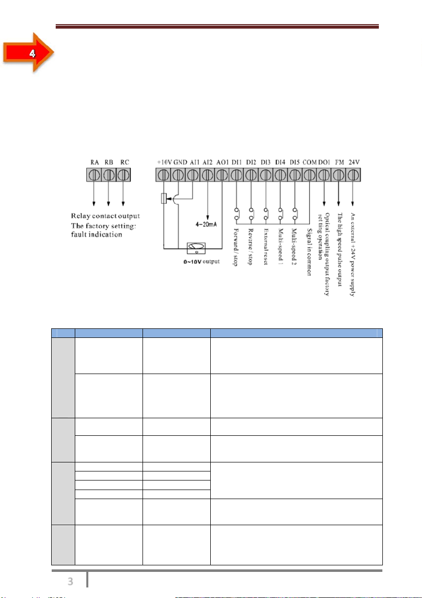
3.2.3 Description of Control Circuit Terminals
[
■ Terminal Arrangement of Control Circuit
■ Description of Control Circuit Terminals
Table 3-3 Description of control circuit terminals
Type Terminal Name Function Description
Power supply
+10V-GND External +10 V
power supply
Provide +10 V power supply to external unit.
Generally, it provides power supply to external
potentiometer with resistance range of 1–5 kΩ.
Maximum output current: 10 mA
+24V-COM External +24V
power supply
Provide +24 V power supply to external unit.
Generally, it provides power supply to DI/DO
terminals and external sensors.
Maximum output current: 20 mA
Connect to +24 V by default.
Analog
input
AI1-GND Analog input 1
Input voltage range: 0–10 VDC
Impedance: 22 kΩ
AI2-GND Analog input 2
Input range: 0–10 VDC/4–20 mA, decided by
jumper J8 on the control board Impedance:
22kΩ(voltage input), 500 Ω(current input)
Digital input
DI1 Digital input 1
Optical coupling isolation, compatible with dual
polarity input Impedance: 2.4 kΩ
Voltage range for level input: 9–30 V
DI2 Digital input 2
DI3 Digital input 3
DI4 Digital input 4
DI5 High-speed
pulse input
Besides features of DI1–DI4 and DI6, it can be
used for high-speed pulse input.
Maximum input frequency: 100 kHz
Analog
output
AO1-GND Analog output 1
Voltage or current output is decided by jumper
J5.
Output voltage range: 0–10 V
Output current range: 0–20 mA

SSI700 User Manual Mechanical and Electrical Installation
www.ssinverter.info
Type Terminal Name Function Description
Digital output
DO1-CME Digital output 1
Optical coupling isolation, dual polarity open
collector output
Output voltage range: 0–24 V
Output current range: 0–50 mA
Note that CME and COM are internally
insulated, but they are shorted by jumper
externally. In this case DO1 is driven by +24 V
by default. If you want to drive DO1 by external
power supply, remove the jumper.
FM- CME High-speed
pulse output
It is limited by P5-00 (FM terminal output mode
selection). As high-speed pulse output, the
maximum frequency hits 100 kHz.
As open-collector output, its specification is the
same as that of DO1
Relay
output
T/A-T/B NC terminal Contact driving capacity:
250 VAC, 3 A, COSø = 0.4
30 VDC, 1 A
Applying to Overvoltage Category II circuit
T/A-T/C NO terminal
COM Digital grounding Please use twisted pair cable or screening wire
3.2.4 Wiring of AC Drive Control Circuit
Figure 3-3 Wiring mode of the AC drive control circuit
Note
• All SSI700 series AC drives have the same wiring mode. The figure here shows the wiring of
Three-phase 220~380 VAC drive. ◎ indicates main circuit terminal, while ○ indicates control
circuit terminal.
SSI700 User Manual Mechanical and Electrical Installation
www.ssinverter.info
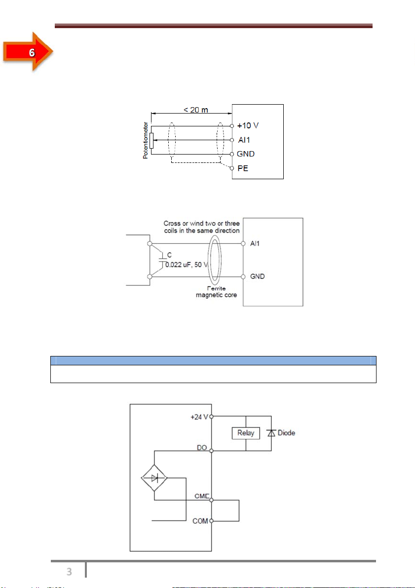
■ Description of Wiring of Signal Terminals
1) Wiring of AI terminals
Weak analog voltage signals are easy to suffer external interference, and therefore the
shielded cable must be used and the cable length must be less than 20 m, as shown in
following figure.
Figure 3-4 Wiring mode of AI terminals
In applications where the analog signal suffers severe interference, install filter capacitor
or ferrite magnetic core at the analog signal source.
Figure 3-5 Install filter capacitor or ferrite magnetic core
2) Wiring of DO terminal
When the digital output terminal needs to drive the relay, an absorption diode shall be
installed between two sides of the relay coil. Otherwise, it may cause damage to the
24 VDC power supply. The driving capacity is not more than 50 mA.
Note
Do not reverse the polarity of the absorption diode during installation, as shown in Figure 3-3.
Otherwise, the 24 VDC power supply will be damaged immediately once there is digital output.
Figure 3-6 DO terminal wiring diagram

Operation, Display and
Application Examples
SSI700 User Manual Operation, Display and Application Example
www.ssinverter.info
Chapter 4 Operation, Display and Application Examples
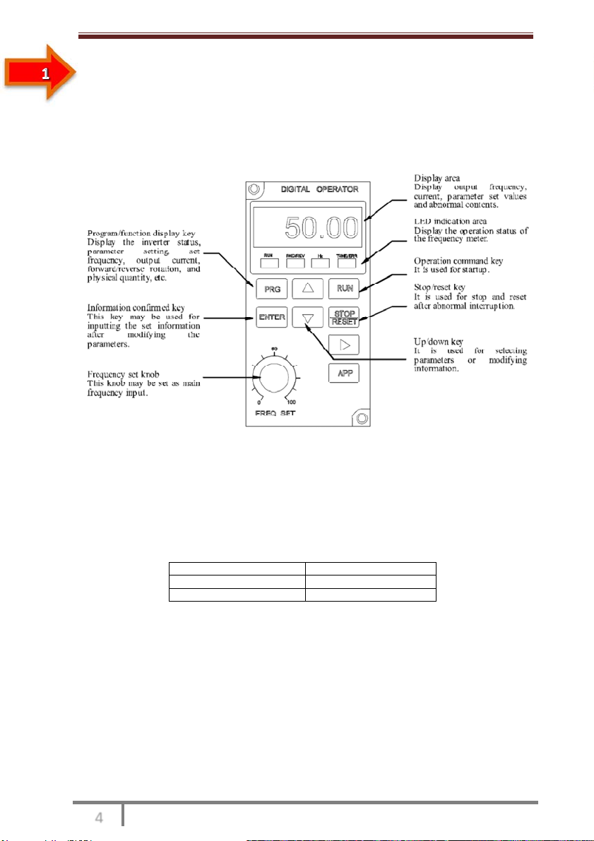
4.1 Operation Panel
You can modify the parameters, monitor the working status and start or stop the SSI700
by operating the operation panel, as shown in the following figure.
Figure 4-1 Diagram of the operation panel
4.1.1 Description of Indicators
• RUN
ON indicates that the AC drive is in the running state, and OFF indicates that the AC drive
is in the stop state.
• LOCAL/REMOT
It indicates whether the AC drive is operated by means of operation panel, terminals or
communication.
LOCAL/REMOT: OFF Operation panel control
LOCAL/REMOT: ON Terminal control
LOCAL/REMOT: blinking Communication control
• FWD/REV
ON indicates reverse rotation, and OFF indicates forward rotation.
• TUNE/TC
When the indicator is ON, it indicates torque control mode. When the indicator is blinking
slowly, it indicates the auto-tuning state. When the indicator is blinking quickly, it indicates
the fault state.
• Unit Indicators
This manual suits for next models
1
Table of contents
Popular Inverter manuals by other brands


XihaBabe
XihaBabe PS-150 instruction manual

Kostal
Kostal PIKO 36 EPC operating manual

Power One
Power One AURORA PVI-OUTD-US Series Installation and operator's manual

AWE
AWE Corona Discharge CD10 Installation and owner's manual

Firman
Firman W03083 owner's manual

Toshiba
Toshiba TOSVERT VF-S15 series instruction manual


