Stober POSIDRIVE MDS 5000 User manual

POSIDRIVE®MDS 5000
Mounting Instructions CONNECTION
MOUNTING
V 5.3
01/2008 GB
MI AM
BCI Field-
bus Applications POSI
Switch®

POSIDRIVE®MDS 5000 – Mounting Instructions
STÖBER
ANTRIEBSTECHNIK
Table of Contents
TABLE OF CONTENTS
1. Notes on Safety 1
1.1 Hardware 2
1.2 Software 3
2. Technical Data 4
2.1 Electrical 4
2.2 Mechanical 9
3. Mechanical Installation 11
3.1 Installation location 11
3.2 Mounting/mounting dimensions 11
3.2.1 Without bottom 11
3.2.2 With bottom brake resistor 12
3.2.3 EMC shield plate and brake
Module for 24 V brake 12
3.3 Installation of accessories 13
3.3.1 Option module 1 (fieldbus) 13
3.3.1.1 CANopen DS-301 (CAN5000) /
PROFIBUS DP-V1 (DP5000) 13
3.3.1.2 EtherCAT (ECS 5000) 14
3.3.2 Option module 2 (terminals) 14
4. Electrical Installation 15
4.1 EMC 15
4.2 RCD circuit breaker 15
4.3 Power connection 15
4.4 Brake module for 24 V brake 16
4.5 DC link coupling 17
4.5.1 Basic Circuit Diagram 17
4.5.2 Combinations 18
4.5.3 Fuses 18
4.6
Safety function „safe torque off“ 19
4.6.1 Description 19
4.6.2 Use 19
4.6.3 Function test 22
4.6.4 Remaining dangers 22
4.7 Cable fabrication 23
4.7.1 Motor cables 23
4.7.2 Connection cable 23
4.8 Installation after storage period 24
5. Connection Allocation 25
5.1 Terminal overview BG 0 to BG 2 25
5.2 Terminal overview BG 3 26
5.3 Terminal allocation (X1 – X302) 27ff
6. Examples of connections 43
6.1 General 43
6.1.1 Brake connection with BRM 5000
for 24 V DC brakes 43
6.1.2 Brake connection with interface relay
for 230 V AC brakes 44
6.1.3 Brake connection with Powerbox 45
6.2 Terminals 46
6.2.1 Example 1 46
6.2.2 Example 2 46
7. Accessories 47
7.1 Accessory overview 47
7.2 Brake resistor 50
7.2.1 FZM(U), FZZM and VHPR 50
7.2.2 FZT, FZZT, FZDT and FGFT 51
7.2.3 Bottom brake resistor RB 5000 52
7.3 Output deraters 53

5th Generation of STÖBER Inverters
STÖBER
ANTRIEBSTECHNIK
1. Notes on Safety
1
1NOTES ON SAFETY
This manual contains information which must be adhered to in order to prevent personal
injury and property damage. This information is graduated by degree of damage as
shown below.
ATTENTION
Means that an undesired result or undesired state may occur if this note is not heeded.
CAUTION
Without warning triangle: Means that property damage may occur if appropriate
precautions are not taken.
CAUTION
With warning triangle: Means that minor personal injury and property damage may occur
if appropriate precautions are not taken.
WARNING
Means that major danger of death and substantial property damage may occur if
appropriate precautions are not taken.
DANGER
Means that great danger to life and substantial property damage will occur if appropriate
precautions are not taken.
NOTE
Indicates an important piece of information on the product or the drawing of attention to a
part of the documentation requiring special attention.
ACTION
Means the description of an action which is particularly important for handling the
product.

5th Generation of STÖBER Inverters
STÖBER
ANTRIEBSTECHNIK
1. Notes on Safety
2
1.1 Hardware
WARNING
To ensure that avoidable problems do not occur during commissioning and/or operation,
be sure to read these installation and commissioning instructions before installation and
commissioning.
In the sense of DIN EN 50178 (formerly VDE 0160), the FDS and MDS model series of
POSIDRIVE®are electrical components of power electronics for the regulation of energy
flow in high-voltage systems. They are exclusively designed to power servo (MDS) and
asynchronous (FDS, MDS) machines. Utilization, installation, operation and maintenance
are only permitted under observation and adherence to valid regulations and/or legal
requirements, applicable standards and this technical documentation.
This is a product of the restricted sales class in accordance with IEC 61800-3. In a
residential zone, this product may cause high-frequency interference in which case the
user may be requested to take suitable measures.
Strict adherence to all rules and regulations must be ensured by the user.
The safety notes contained in further sections (items) and specifications must be
adhered to by the user.
WARNING
Caution! High touch voltage! Danger of shock! Danger to life!
When network voltage is applied, never under any circumstances open the housing or
disconnect the connections. When installing or removing option boards, you may only
open the inverter in the dead state (all power plugs disconnected) and only after a
waiting period of at least 5 minutes after the network voltage is switched off. Prerequisite
for the correct functioning of the inverter is the correct configuration and installation of
the inverter drive. Transport, installation, commissioning and handling of the device may
only be performed by qualified personnel who have been especially trained for these
tasks.
Pay particular attention to the following:
•Permissible protection class: Protective ground. Operation is only permitted when the
protective conductor is connected in accordance with regulations. Direct operation of
the devices on IT networks is not possible.
•Installation work may only be performed in the dead state. For work on the drive, lock
enable and disconnect the complete drive from the power. (Observe the 5 safety
rules.)
•Leave the plug for the DC link coupling connected even when the DC link coupling is
not being used (BG0-BG2: X22)!
•Discharge time of the DC link capacitors > 5 minutes.
•Do not penetrate the device's interior with any kind of object.
•During installation or any other work in the switching cabinet, protect the device
against falling parts (pieces of wire, stranded wire, pieces of metal, and so on). Parts
with conductive properties may cause a short circuit within the inverter or device
failure.
•Before commissioning, remove extra coverings so that the device cannot overheat.
The inverter must be installed in a switching cabinet in which the maximum ambient
temperature (see technical data) is not exceeded. Only copper lines may be used. The
line cross sections to be used are contained in table 310-16 of the NEC standard at
60 oC or 75 oC.
The company STÖBER ANTRIEBSTECHNIK GmbH + Co. KG accepts no liability for
damages resulting from non-adherence to the instructions or the particular
regulations.

5th Generation of STÖBER Inverters
STÖBER
ANTRIEBSTECHNIK
1. Notes on Safety
3
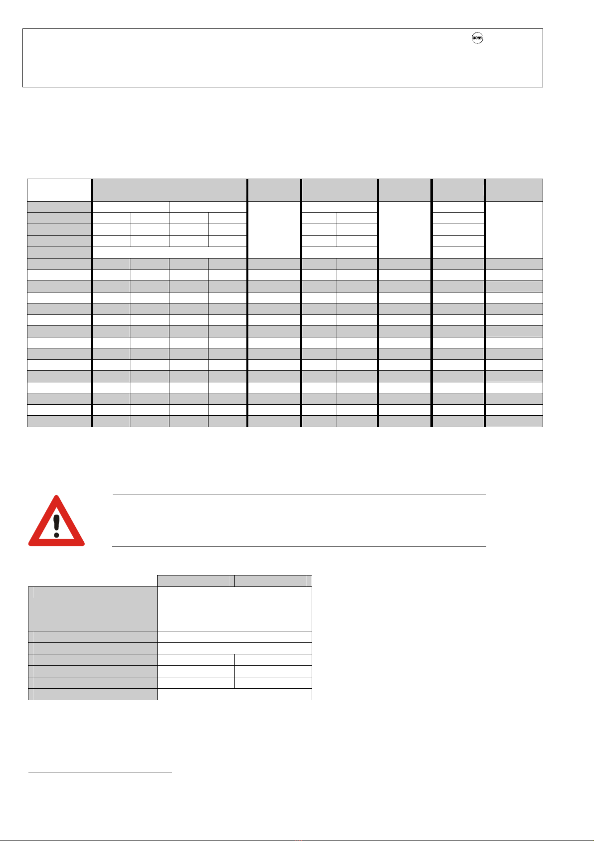
The motor must have an integral temperature monitor with basis insulation as per
EN 61800-5-1 or external motor overload protection must be used.
Only suitable for use on supply current networks which cannot deliver more than a
maximum symmetric, nominal, short-circuit current of 5000 A at 480 Volt.
Integral solid state short circuit protection does not provide branch circuit protection.
Branch circuit protection must be provided in accordance with the Manufacturer
Instructions, National Electrical Code and any additional local codes”, or the equivalent.
Suitable for use on a circuit capable of delivering not more than 10 kA rms. Symmetrical
Amperes, 480 Volts Maximum” when Protected by RK1 Class Fuses as specified in the
chapter technical data.
Subject to technical changes without prior notification which changes serve to
improve the devices. This documentation is purely a product description. It does
not represent promised properties in the sense of warranty law.
1.2 Software
Use of the POSITool software
The POSITool software package can be used to select an application, adjust parameters
and signal monitoring of the 5th generation of STÖBER inverters. The functionality is
specified by the selection of an application and the transmission of these data to an
inverter.
The program is the property of STÖBER ANTRIEBSTECHNIK GmbH + Co. KG and is
protected by copyright. The program is licensed for the user.
The software is provided exclusively in machine-readable format.
The customer receives from STÖBER ANTRIEBSTECHNIK GmbH + Co. KG a non-
exclusive right to use the program (license) if the program was obtained legally.
The customer has the right to utilize the program for the above stated activities and
functions and to make and install copies of the program, including one backup copy, for
support of said utilization.
The conditions of this license apply to all copies. The customer is obligated to place the
copyright note and all other ownership notes on every copy of the program.
The customer is not authorized to use, copy, change or pass on/transmit the program for
reasons other than those covered by these conditions; the customer is also not
authorized to convert the program (reverse assembly, reverse compilation) or compile
the program in any other manner, or to sublicense, rent or lease the program.
Product maintenance
The obligation to perform maintenance applies to the two last current program versions
prepared and released for use by STÖBER ANTRIEBSTECHNIK GmbH + Co. KG.
STÖBER ANTRIEBSTECHNIK GmbH + Co. KG can either correct program errors or
provide a new program version. The choice is up to STÖBER ANTRIEBSTECHNIK
GmbH + Co. KG. If, in individual cases, the error cannot be corrected immediately,
STÖBER ANTRIEBSTECHNIK GmbH + Co. KG will provide an intermediate solution
which, if necessary, requires adherence by the user to special operating regulations.
The claim to error correction only exists when reported errors are reproducible or can be
recorded by machine-made outputs. Errors must be reported in reconstructable form
giving useful information for error correction.
The obligation to correct errors is invalidated for such programs which the customer
changes or manipulates unless the customer can prove when reporting the error that the
manipulation is not the cause of the error.
STÖBER ANTRIEBSTECHNIK GmbH + Co. KG is obligated to keep the currently valid
program versions in a specially protected place (fire-resistant data safe, safety deposit
box at a bank).

POSIDRIVE®MDS 5000 – Mounting Instructions
STÖBER
ANTRIEBSTECHNIK
2. Technical Data
4
2TECHNICAL DATA
Model key
MDS 5075/L
2.1 Electrical
General (for all sizes)
Output voltage 3 x 0 V up to connection voltage
Output frequency 0 – 400 Hz
Radio interference suppression EN 61800-3, interference emission, class C3
International certifications UL and cUL
Storage/transportation temperature -20 °C to +70 °C, max. of change: 20 K / h
Max. surrounding air temperature 0 to 45 °C with rated data,
up to 55 °C with power reduction of 2.5% / °C
Relative humidity during operation Relative humidity 85%, no condensation
Altitude of installation Up to 1000 m above sea level without restriction
1000 to 2000 m above sea level with power reduction of 1.5% / 100 m
High voltage category III in accordance with EN 61800-5-1
Degree of soil Degree of soil 2 in accordance with EN 60204 / EN 50178
Protection rating IP 20
Installation position Generally vertical
Ventilation Built in fan
Upper voltage limit 830 V
Brake chopper on level 780 V / 800 V
Brake chopper disable voltage 740 V / 760 V
5th generation
Powe
r
075 = 7.5 kW
A
uxiliary voltage, control electronics
/L ... Low level, 24 V external
/H ... High level, DC link
Designation

POSIDRIVE®MDS 5000 – Mounting Instructions
STÖBER
ANTRIEBSTECHNIK
2. Technical Data
5
Size 0 / BG 0
Device Type MDS 5007 MDS 5004
Under preparation MDS 5008 MDS 5015
ID no. 44556 44555 44557 44558
Recommended motor
power 0.75 kW 0.37 kW 0.75 kW 1.5 kW
Connection voltage (L1-N) 1 x 230 V
+20%/-40%, 50/60Hz
(L1-L3) 3 x 400 V +32%/-50% 50 Hz
(L1-L3) 3 x 480 V +10%/-58% 60 Hz
Power fuses11 x 10 AT 3 x 6 AT 3 x 6 AT 3 x 10 AT
Operation with servo motor (control mode servo control)
Rated current IN3 x 3.0 A 3 x 1.0 A 3 x 1.5 A 3 x 3.0 A
Imax 250% / 2 sec., 200% / 5 sec.
Clock pulse frequency 8 kHz
Operation with three-phase current motor (control mode V/f, VC, SLVC)
Rated current IN3 x 4.0 A 3 x 1.3 A 3 x 2.1 A 3 x 4.0 A
Imax 180% / 5 sec., 150% / 30 sec.
Clock pulse frequency 4 kHz (adjustable up to 16 kHz with derating)
Brake resistor
(accessories),
cf. chap. 7.2
100 Ω: Max. of
1.6 kW 200 Ω: Max. of 3.2 kW
Perm. motor cable
length, shielded
50 m
Output derating is required for distances of 50 m to 100 m (see chapter 7.2.4).
Power loss at Ia = IN80 W 50 W 65 W 90 W
Power loss at Ia = 0A2Max. of 30 W2
Conductor cross
section Max. of 2.5 mm2
Dimensions (H x B x T)
[mm] 300 x 70 x 175 (193)3
without
packaging 2.2
Weight
[kg] with
packaging 3.2
Upper voltage limit 440 V 830 V
Brake chopper on level 400 V / 420 V 780 V / 800 V
Brake chopper disable
voltage 360 V / 380 V 740 V / 760 V
An external brake resistor may be required during generator operation.
A temperature-monitored brake resistor is required for UL/cUL-conform operation.
1Line circuit breaker, tripping characteristic C, EN 60 898
Use class RK1 fuses for UL adherence: Class RK1 (e.g., Bussmann KTS-R-xxA / 600 V)
2Depends on the option boards and sensors connected (e.g., encoder)
3Depth including braking resistor RB 5000

POSIDRIVE®MDS 5000 – Mounting Instructions
STÖBER
ANTRIEBSTECHNIK
2. Technical Data
6
Size 1 / BG 1
Device Type MDS 5040 MDS 5075
ID no. 44560 44561
Recommended
motor capacity 4.0 kW 7.5 kW
Connection voltage (L1-L3) 3 x 400 V +32%/-50% 50 Hz
(L1-L3) 3 x 480 V +10%/-58% 60 Hz
Power fuses13 x 16 AT 3 x 20 AT
Operation with servo motor (control mode servo control)
Rated current IN3 x 6.0 A 3 x 10 A
Imax 250% / 2 sec., 200% / 5 sec.
Clock pulse frequency 8 kHz
Operation with three-phase current motor (control mode V/f, VC, SLVC)
Rated current IN3 x 10 A 3 x 16 A
Imax 180% / 5 sec., 150% / 30 sec.
Clock pulse frequency 4 kHz (adjustable up to 16 kHz with derating)
Brake resistor
(accessories),
cf. chap. 7.2
100 Ω: Max. of 6.4 kW 47 Ω: Max. of 13.6 kW
Perm. motor cable
length, shielded
50 m
Output derating is required for distances of 50 m to 100 m (see chapter 7.2.4).
Power loss
at Ia = IN170 W 200 W
Power loss
at Ia = 0A2Max. of 30 W2
Conductor cross
section Max. of 4 mm2
Dimensions (H x B x T)
[mm] 300 x 70 x 260 (278)3
without
packaging 3.8
Weight
[kg] with
packaging 5.1
Upper voltage limit 830 V
Brake chopper on level 780 V / 800 V
Brake chopper disable
voltage 740 V / 760 V
An external brake resistor may be required during generator operation.
A temperature-monitored brake resistor is required for UL/cUL-conform operation.
1Line circuit breaker, tripping characteristic C, EN 60 898
Use class RK1 fuses for UL adherence: Class RK1 (e.g., Bussmann KTS-R-xxA / 600 V)
2Depends on the option boards and sensors connected (e.g., encoder)
3Depth including braking resistor RB 5000

POSIDRIVE®MDS 5000 – Mounting Instructions
STÖBER
ANTRIEBSTECHNIK
2. Technical Data
7
Size 2 / BG 2
Device Type MDS 5110 MDS 5150
ID no. 44562 44563
Recommended
motor capacity 11 kW 15 kW
Connection voltage (L1-L3) 3 x 400 V +32%/-50% 50 Hz
(L1-L3) 3 x 480 V +10%/-58% 60 Hz
Power fuses13 x 35 AT 3 x 50 AT
Operation with servo motor (control mode servo control)
Rated current IN3 x 14 A 3 x 20 A
Imax 250% / 2 sec., 200% / 5 sec.
Clock pulse frequency 8 kHz
Operation with three-phase current motor (control mode V/f, VC, SLVC)
Rated current IN3 x 22 A 3 x 32 A
Imax 180% / 5 sec., 150% / 30 sec.
Clock pulse frequency 4 kHz (adjustable up to 16 kHz with derating)
Brake resistor
(accessories),
cf. chap. 7.2
22 Ω: Max. of 29 kW
Perm. motor cable
length, shielded
50 m
Output derating is required for distances of 50 m to 100 m (see chapter 7.2.4).
Power loss
at Ia = IN220 W 280 W
Power loss
at Ia = 0A2Max. of 30 W2
Conductor cross
section Max. of 6 mm2
Dimensions (H x B x T)
[mm] 300 x 105 x 260 (278)3
without
packaging 5.0
Weight
[kg] with
packaging 6.1
Upper voltage limit 830 V
Brake chopper on level 780 V / 800 V
Brake chopper disable
voltage 740 V / 760 V
An external brake resistor may be required during generator operation.
A temperature-monitored brake resistor is required for UL/cUL-conform operation.
1Line circuit breaker, tripping characteristic C, EN 60 898
Use class RK1 fuses for UL adherence: Class RK1 (e.g., Bussmann KTS-R-xxA / 600 V)
2Depends on the option boards and sensors connected (e.g., encoder)
3Depth including braking resistor RB 5000

POSIDRIVE®MDS 5000 – Mounting Instructions
STÖBER
ANTRIEBSTECHNIK
2. Technical Data
8
Size 3 / BG 3
Device Type MDS 5220 MDS 5370 MDS 5450
ID no. 44564 44566 44567
Recommended
motor capacity 22 kW 37 kW 45 kW
Connection voltage (L1-L3) 3 x 400 V +32%/-50% 50 Hz
(L1-L3) 3 x 480 V +10%/-58% 60 Hz
Power fuses13 x 50 A gG23 x 80 A gG2
Operation with servo motor (control mode servo control)
Rated current IN3 x 30 A 3 x 50 A 3 x 60 A
Imax 250% / 2 sec., 200% / 5 sec.3
Clock pulse frequency 8 kHz
Operation with three-phase current motor (control mode V/f, VC, under preparation: SLVC)
Rated current IN3 x 44 A 3 x 70 A 3 x 85 A
Imax 180% / 5 sec., 150% / 30 sec.3
Clock pulse frequency 4 kHz (adjustable up to 16 kHz with derating)
Brake resistor internal 30 Ω: 100 W / max. of 21 kW
Brake resistor external
(accessories), cf.
chap. 7.2
15 Ω: max. of 42 kW
Perm. motor cable
length, shielded 100 m
Power loss
at Ia = INApprox. 350 W Approx. 600 W Approx. 1000 W
Power loss
at Ia = 0A4max. of 55 W4
Conductor cross
section Max. of 35 mm2without core end sleeve
Dimensions (H x B x T)
[mm] 382.5 x 190 x 276
without
packaging 11.8 13.2 13.2
Weight
[kg] with
packaging 13.6 15.0 15.0
Upper voltage limit 830 V
Brake chopper on level 780 V / 800 V
Brake chopper disable
voltage 740 V / 760 V
An external brake resistor may be required during generator operation.
A temperature-monitored brake resistor is required for UL/cUL-conform operation.
1Line circuit breaker, tripping characteristic C, EN 60 898
Use class RK1 fuses for UL adherence: Class RK1 (e.g., Bussmann KTS-R-xxA / 600 V)
2Operation with network commutating inductors and power fuses for operation class gG (full range fuses for cable and line
protection in accordance with IEC 60269-2-1 / DIN VDE 0636, part 201 NH fuses).
3The effective current must be ≤the rated current, averaged over 10 minutes.
4Depends on the option boards and sensors connected (e.g., encoder)

POSIDRIVE®MDS 5000 – Mounting Instructions
STÖBER
ANTRIEBSTECHNIK
2. Technical Data
9
2.2 Mechanical
BG 0 / BG 1 BG 2
w
ba
h
hb
d1
d2*
f
e
w
ESC
X3
I/O
Dimensions in mm BG 0 BG 1 BG 2
Height h 300
Height
(incl. EMC shield plate) hb 360
Width w 70 105
d1 175 260 260
Inverter
base plate
Depth d2* 193 278 278
Height e 37.5
EMC shield plate Depth f 40
Distance a 283
Mounting holes Vertical position
on the base plate b 6
Without packaging 2.2 3.8 5.0
Weight [kg] With packaging 3.2 5.1 6.1
* d2 = Depth incl. brake resistor RB 5000
Min. Free Space
[Dimensions in mm] Up Down To Right To Left Screws
Without EMC shield plate 100 100 5 5
With EMC shield plate 100 120 5 5 M5
For position, designation and allocation
of the terminals, see chap. 5.
EMC shield plate

POSIDRIVE®MDS 5000 – Mounting Instructions
STÖBER
ANTRIEBSTECHNIK
2. Technical Data
10
Size 3 / BG 3
ESC
X3
I/O
276
150
150
190
20
6
20
20
20
382,5
3
6
5
POSIDRIVE
®
MDS 5000
BRM 5000
BG 3
Dimensions in mm MDS 5220 MDS 5370 MDS 5450
Height 382.5
Width 190
Inverter
base plate
Depth 276
Vertical (distance) 365
Vertical position
on the base plate 6
Mounting holes
Horizontal (distance) 150
Without packaging 11.8 13.2 13.2
Weight [kg] With packaging 13.6 15.0 15.0
Dimensions in mm Up Down To Right To Left Screws
Min. free space 100 100 5 5 M5

POSIDRIVE®MDS 5000 – Mounting Instructions
STÖBER
ANTRIEBSTECHNIK
3. Mechanical Installation
11
3MECHANICAL INSTALLATION
This chapter gives you complete information on the subject of mechanical installation.
Only specialized personnel who are qualified for this task may install, commission and operate the device.
3.1 Installation Location
•Operate only in closed switching cabinet (adhere to protection rating IP 20).
•Install inverter only in vertical position.
•Avoid installation above heat-generating devices.
•Ensure sufficient air circulation in the switching cabinet
(Adhere to minimum free spaces as per table in chap. 3.2.).
•Installation site free of dust, corrosive fumes and all liquids
(in accordance with soiling degree 2 in accordance with EN 60204 / EN 50178)
•Avoid atmospheric humidity.
•Avoid condensation (e.g., due to anti-condensation heating elements).
•To meet EMC requirements, use mounting plates with conductive surface (e.g., unpainted).
3.2 Mounting/Mounting Dimensions
3.2.1 Without Bottom
283
BG 0 – BG 2
150
3
6
5
BG 3 Min. Free
Space
[Dimensions
in mm]
A
Up
B
Down
C
To Right
/ Left
Screws
BG 0 – BG 2
Without EMC
shielding plate 100 100 5 M5
BG 0 – BG 2
With EMC
shielding plate 100 120 5 M5
BG 3 100 100 5 M5
A
B
C
C
Drilling jigs Free space

POSIDRIVE®MDS 5000 – Mounting Instructions
STÖBER
ANTRIEBSTECHNIK
3. Mechanical Installation
12
D
A
C
B
B
3.2.2 With Bottom Brake Resistor
Available for BG 0 to BG 2.
The "brake resistor RB 5000" substructure is the ideal solution when space is
limited. It is placed between mounting surface and MDS 5000. This increases
the mounting depth by approx. 20 mm.
Mounting
•Secure the bottom brake resistor (A) on the mounting surface
with the included threaded bolts and spring rings (same drilling
diagram as MDS 5000) (B).
•Hook the MDS 5000 in on the four guides (C).
•Secure the MDS 5000 to the threaded bolts with the two
included screws (D).
3.2.3 EMC Shield Plate and Brake Module for 24 V Brake
The EMC shield plate (EM 5000) and the brake module for 24 V brake
(BRM 5000) are physically identical units (cf. accessories, chap. 7.1).
If necessary, the EMC shield plate can be replaced by the
brake module for 24 V brake. See also chap. 4.4.
BG 0 – BG 2
•Position the EMC shield plate at a slight angle and insert the
two brackets in the provided openings (B).
•Hook in the EMC shield plate.
•Secure the device and the EMC shield plate with the
mounting screw (C).
•If already installed, secure the motor cable with the EMC
clamp (A).
•Check to make sure that the shield of motor cable is
positioned flat on the EMC shield plate with the EMC clamp.
See also chap. 4.7.
BG 3
•Unscrew the screw (D) on the lower portion of the housing front.
•Place the brake module for 24 V brake with the two tabs in the two cutouts (E)
in the housing front.
•Secure the brake module for 24 V brake with the screw (D).
A
C
B
D
E
p
art o
f
BG
3

POSIDRIVE®MDS 5000 – Mounting Instructions
STÖBER
ANTRIEBSTECHNIK
3. Mechanical Installation
13
3.3 Installation of Accessories
Only specialized personnel who are qualified for this task may install accessories (cf. chap. 7). Suitable measures must be
provided against damage by electrostatic discharging (in accordance with DIN EN 50082-2). Before installation, the device must
be disconnected from the power and, with the MDS 5xxx/L series, the 24 V power must be turned off. Remember the discharge
times (≥5 min.) for the DC link.
CAUTION
Immediately after the power is turned off, the DC link is still charged. Wait > 5 min. for the DC link to discharge
after turning off the power voltage. To prevent damage to device and accessory parts, install the accessory
afterwards.
CAUTION
Danger of electrostatic charges damaging the PCB!
Perform potential equalization before you touch a PCB (option module 1 and 2).
3.3.1 Option module 1 (fieldbus)
3.3.1.1 CANopen DS-301 (CAN5000) / PROFIBUS DP-V1 (DP5000)
Installation is the same for both modules.
•Make sure that the device is without power. Wait ≥5 min. for the DC link capacitors to discharge after turning off the power
supply voltage.
•Disconnect the cover plate by removing the two screws (E).
•Remove the prepunched area (A) for the sub D plug connector on the plate.
•Mount the plate on the board with the included UNC bolts (B).
•Slide the fieldbus board (C) with the gold-contacted terminal surfaces (D) into the black terminal block.
CAUTION
Be sure not to touch the gold contact surface with your fingers (danger of fouling and corrosion).
•Check correct position of the board.
•Secure the board with the two included screws (E).
•Then apply included labels (nameplate and adhesive label for switch setting (CAN)) to the cover plate.
A
D
BCAN5000
DP5000
C
E

POSIDRIVE®MDS 5000 – Mounting Instructions
STÖBER
ANTRIEBSTECHNIK
3. Mechanical Installation
14
3.3.1.2 EtherCAT (ECS 5000)
•Make sure that the device is without power. Wait ≥5 min. for the DC link capacitors to discharge after turning off the power
supply voltage.
•Disconnect the cover plate by removing the two screws (C).
•Slide the EtherCAT board (A) with the gold-contacted terminal surfaces (B) into the black terminal block.
CAUTION
Be sure not to touch the gold contact surface with your fingers (danger of fouling and corrosion).
•Check correct position of the board.
•Secure the board with the two included screws (C).
•Then apply included labels (nameplate) to the cover plate.
3.3.2 Option module 2 (terminals)
•Standard (SEA 5000, SEA 5001)
•Expanded (XEA 5001)
•Resolver (REA 5000)
Installation is the same for all modules.
•Make sure that the device is without power.
•Before installation, remove the blue plastic cover (A) below the serial interface
(terminal X3).
•Make sure that the device is without power.
•Unlock the snap-on lock (B) directly below terminal X3 and, on the snap-on
lock, pull the cover towards the front.
•To completely unhook the cover, pull this in the direction of the operator panel.
•Push the I/O terminal module with the gold-contacted terminal surface (C)
into the black terminal block (D).
CAUTION
Be sure not to touch the gold contact surface with your fingers
(danger of fouling and corrosion).
•Check correct position of the board.
•Secure the board with the two included screws (E).
•Now hook the plastic cover (A) with the two catches into the plastic housing.
•Press the plastic cover (A) against the plastic housing until the snap-on lock
(B) snaps in.
D
A
C
E
B
ECS 5000
A
C
B

POSIDRIVE®MDS 5000 – Mounting Instructions
STÖBER
ANTRIEBSTECHNIK
4. Electrical Installation
15
4ELECTRICAL INSTALLATION
This chapter gives you complete information on the subject of electrical installation.
Only specialized personnel who are qualified for this task may install, commission and control the device.
4.1 EMC
This chapter contains general information on EMC-suitable installation. These are only recommendations. Depending on the
application, the ambient conditions and the legal requirements, measures in addition to the following recommendations may be
required.
•Mount device or Bottom Brake Resistor on conductive surface (unpainted).
•Install the power cables in spatially separately from the signal lines (encoder, analog/digital signal lines).
•Use only shielded cable for motor lines (corresponding cabels can be ordered from STÖBER ANTRIEBSTECHNIK.).
•Apply shield of the motor cable over a large surface in the immediate vicinity of the MDS 5000. The EMC shield plate (EM
5000) for mounting on the bottom of the device is available as an accessory (see chap. 3.2.3 and chap. 7.1).
•With asynchronous machines, apply the shield to the terminal block over a large surface (e.g. PG shield screw connection).
•Use output deraters for motor lines > 50 m.
•When an additional transfer plug connector is to be installed in the motor cable, the cable shield may not be interrupted.
•When the brake line is installed in the motor cable, the brake line must be shielded separately.
•When the length of the cable for connection of a brake resistor is longer than 30 cm, this must be shielded and the shield
must be applied over a large surface in the immediate vicinity of the MDS 5000.
•Connect the shield of the control lines on one side with reference ground of the reference value source (e.g., PLC or CNC).
•Shield, and, if necessary, twist reference value lines before installing.
4.2 RCD (Residual Current Protective Devices)
Network phases and neutral conductors are connected with the protective conductor via Y capacitors. When network voltage is
applied, a leakage current flows over these capacitors to the protective conductor. The greatest leakage current occurs during a
malfunction (asymmetric feedin via only one phase) and during power-on (sudden change in voltage). The maximum leakage
current due to asymmetric power feedin is 40 mA (network voltage of 400 V) for MDS inverters.
If RCD circuit breakers are necessary, the problem of power-on and off can be alleviated by using selective RCD circuit
breakers (switch-off delay) or RCD circuit breakers with increased tripping current (e.g., 300 or 500 mA). Only all-current
sensitive RCD circuit breakers may be used. Operation of several devices on one RCD circuit breaker is not recommended.
4.3 Power Connection
Protection via line circuit breakers in accordance with the values listed in chap. 2 (tripping characteristic C, in accordance with
EN 60 898) or suitable, delayed safety fuse.
Use class RK1 fuses for UL conformance: Class RK1 (e.g., Bussmann KTS-R-xxA / 600 V)

POSIDRIVE®MDS 5000 – Mounting Instructions
STÖBER
ANTRIEBSTECHNIK
4. Electrical Installation
16
4.4 Brake Module for 24 V Brake
The relay in the basic device for brake control is equipped with hardgold contacts. This relay is designed for control of an
electro-magnetic brake. The brake module for 24 V brake is required for control of a 24 V brake (BRM 5000). A thermally
monitored and short-circuit-proof, electronic semi-conductor switch is available for switching the brake. When Brake module for
24 V brake is placed between relay and brake, the integrated filter suppresses the switch-off reactions. This also increases the
lifespan of the relay contacts.
For a 230 VAC brake we also recommend control via
a coupling relay and not directly via the existing relay.
Installation
•Connect terminal X302 with terminal X2
(for connection cable, see chap. 4.7.2).
•Connect the external 24 V to the power supply of the
brake on X300 an (for pin allocation, see chap. 5.3).
•The brake and thermal contact lines installed in the motor
cable are connected to X301 (for pin allocation, see chap. 5.3).
24 V
X2
18
45
4
+
1
+
X301
X300
X302
Brake module
for 24 brake
(BRM 5000) •cf. chap. 7.1
X
302
X2
X
301
X
300
MDS 5000
Brake module
for 24 V brake
MDS
Internal
circuiting
Filte
r
Brake
control
Positor line
(temperature
sensor f. motor)

POSIDRIVE®MDS 5000 – Mounting Instructions
STÖBER
ANTRIEBSTECHNIK
4. Electrical Installation
17
4.5 DC Link Coupling
If you are using axes in a plant which operate in a network of generators and motors, the DC link coupling (DC coupling) can be
advantageous. When the DC-coupling is used, the excess energy of other axes is made available as drive power instead of
converting this excess power into heat with a brake resistor. Remember that you will need a brake resistor which can absorb the
power peaks when all drives in the DC-link network brake at the same time.
DANGER
Danger of damage to devices! When single-phase and three-phase devices are coupled,
the single-phase devices will be destroyed. Use only three-phase devices for the DC link
coupling!
CAUTION
Danger of damage to devices! When one device within the DC-link coupling network fails,
the complete DC-link coupling network must be disconnected from the power network since
other devices in the DC-link coupling network may be damaged. Be sure to adhere to the
wiring of the ready-for-operation relay shown in chapter 4.5.1 (X1.1 and X1.2). When a
failure occurs, replace all devices of one group.
NOTE
Please note that the parameter A38 DC power-input must be set before the DC link
coupling will function correctly.
Group 1: A38 = 0: inactive
Group 2 and 3: A38 = 1: active
For more details, also see the description of the parameter.
4.5.1 Basic Circuit Diagram
The following diagram shows the basic circuiting of the DC-link coupling. The inverters can be coupled together in up to three
groups. The table in chapter 4.5.2 shows the possible combinations. The combination determines the types of power fuse and
DC-link fuse.
MDS/FDS
5000
MDS/FDS
5000
MDS/FDS
5000
MDS/FDS
5000
MDS/FDS
5000
MDS/FDS
5000
MDS/FDS
5000
X10 X10 X10 X10X10 X10 X10
X1 X1 X1 X1X1 X1 X1
X22
1
X22
1
X22 X22X22
1
X22 X22
U+
RB RB U+ U+ U+U+ U+ U+U- U- U- U-U- U- U-
11 1 11112222222
L1
L2
L3
PE
BTB
2
Figure 4-1 Basic circuit diagram for the DC link coupling
1 For MDS 5000 devices of size BG3: X20, terminals DC-link +, DC-link -
2 Dimension the brake resistor to fit the braking power of the DC-link network and the technical data of the device.
Group 1
Group 2 Group 3
Powe
r
fuse
DC-link fuse DC-link fuse
Floating signal
contact - must be
integrated in the
safety circuit of the
controller.
B
r
aking
resistor

POSIDRIVE®MDS 5000 – Mounting Instructions
STÖBER
ANTRIEBSTECHNIK
4. Electrical Installation
18
4.5.2 Combinations
The following table shows the possible combinations for the DC-link coupling. A total of 15 combinations are available.
Example: Combination no. 7
This combination lets you combine one size-1 inverter in group 1 with two size-0 devices in group 2. There is no group 3. The
power fuse must have a nominal current of 20 A. The groups are separated from each other with the type-1 DC-link fuse (see
chapter 4.5.3). Wait three minutes before turning on the devices of the DC-link coupling again.
Group 1 DC-Link
Fuse Group 2 DC-Link
Fuse Group 3 Switchon Wait
Time [min]
Type MDS/FDS 5000 MDS 5000 MDS/FDS 5000 MDS/FDS
Size BG0 BG1 BG2 BG3 BG0 BG1 BG0
Power fuse110 A 20 A 50 A 80 A – – –
Max. P-IN 4 kW 10 kW 20 kW 45 kW – – –
Combinationno.
1 max. 4 – – 1
2 max. 4 – – 5
3 3 Type 1 2 – 5
4 3 Type 1 1 – 3
5 2 Type 1 2 – 3
6 2 Type 1 1 – 4
7 1 Type 1 2 – 3
8 max.3 – – 2
9 3 Type 2 1 Typ 1 2 2
10 3 Type 1 2 – 2
11 3 Type 2 1 – 2
12 2 Type 2 1 – 2
13 2 Type 2 1 Typ 1 1 2
14 1 Type 1 1 – 2
15 max. 3 – 1
Instead of delaying the process by the switchon wait time, you can determine the switchon point in time by evaluating parameter
E14. The parameter must indicate in all-network connected devices that the charging relays are open before the voltage can be
switched through again. You can query the parameter via fieldbus or binary output.
4.5.3 Fuses
CAUTION
Danger of machine standstill! When one fuse element fails, the second fuse element is
damaged. Always replace the elements of a fuse in pairs.
Use the following fuses to protect the DC-link coupling:
Type 1 Type 2
Manufacturer SIBA Sicherungs-Bau GmbH
Borker Straße 22
D-44534 Lünen
www.siba.de
Size 10 x 38
Rated voltage AC 500 V
Rated current 10 A 20 A
Power loss per element 1.6 W 3,5 W
Art. no. of fuse 60 034 34.10 60 034 34.20
Art. no. of fuse holder 51 063 04.3
1For use conforming to UL, see specifications in the technical data.
Keep the following points in mind during installation
and operation:
•Use shielding for DC-link coupling connections
longer than 20 cm. This will prevent EMC problems.
•Use the two outer elements of the fuse holder.
Other manuals for POSIDRIVE MDS 5000
3
Table of contents
Other Stober Inverter manuals

Stober
Stober POSIDRIVE FDS 5000 series User manual

Stober
Stober POSITool MDS 5000 User manual

Stober
Stober POSIDRIVE FDS 5000 series User manual

Stober
Stober POSIDRIVE MDS 5000 User manual

Stober
Stober POSIDYN SDS 5000 User manual

Stober
Stober ComTrac User manual

Stober
Stober MDS 5000 User manual

Stober
Stober POSYDYN SDS 4281 Operator's manual