14
3.2 System design and installation 3. Installation
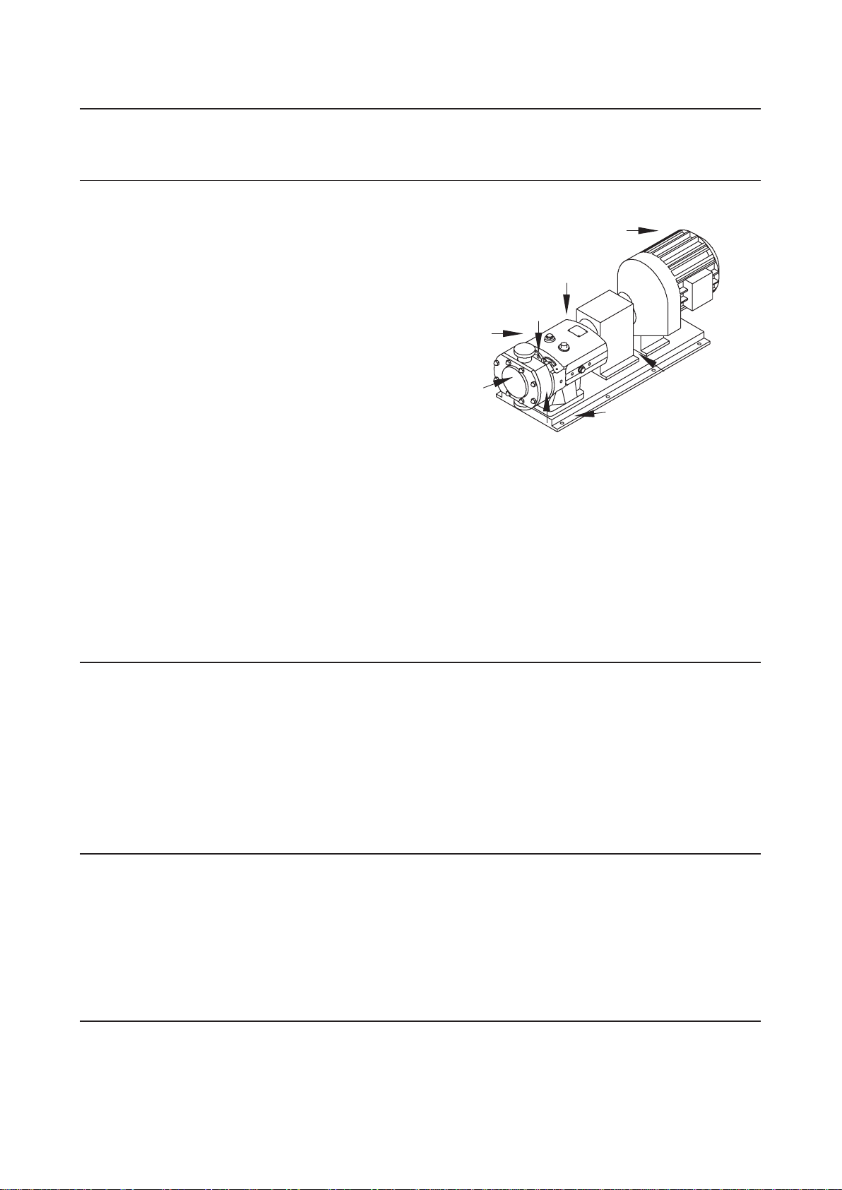
Pump Lubrication:
The pump will not be supplied pre-filled with oil therefore this table must be used to select recommended oil.
Oil changing: Oil level must be checked with the pump static.
First change: After 150 hours of operation, thereafter every 3000 hours of operation.
Oil filling: Fill with oil through the filler plug to the level indicated in the sight glass.
NOTE!
On horizontally ported pumps the sight glass must be fitted to the upper hole on the side of the gearcase.
Refer to technical data (chapter 5) for oil approximate quantities required.
Recommended Oils
Pump Operating Temperature Food grade oils (USDA H1)
-20°C to +130°C +130oC to 200°C -20°C to +130°C
(-4°F to +266°F ) (+266°F to 392°F) (-4°F to +266°F)
BP Energol GR - XP150 BP Enersyn SG150 Bel-Ray No-Tox gear oil ISO grade 150, product # 6243.
Castrol Alpha SP150 Castrol Alphasyn PG150 Mobil DTE FM 150
Mobil Gear 629 Mobil Glygoyle 30 Optimol Optileb GT 150
Shell Omala 150 Shell Tivela S150 Castrol Vitalube GS 150.food grade
Texaco Meropa 150 Texaco Synlube CLP220
Esso Spartan EP150 Mobil Glygoyle 22
For ATEX applications refer to ATEX addendum manual.
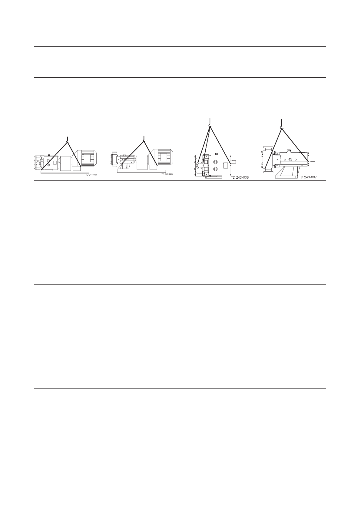
Baseplate Foundations
Pumps when supplied with a drive unit are normally mounted on a baseplate. Our standard baseplates have pre-drilled
fixing holes to accept base retaining bolts. To provide a permanent rigid support for securing the pump unit, a foundation is
required which will also absorb vibration, strain or shock on the pumping unit. Methods of anchoring the baseplate to the
foundation are varied, they can be studs embedded in the concrete either at the pouring stage as shown below, or by use of
epoxy type grouts. Alternatively mechanical fixings can be used.
The foundation should be appox. 150 mm longer and wider than the baseplate. The depth of the foundation should be pro-
portional to the size of the complete pump unit. For example, a large pump unit foundation depth should be at least 20 times
the diameter of the foundation bolts.
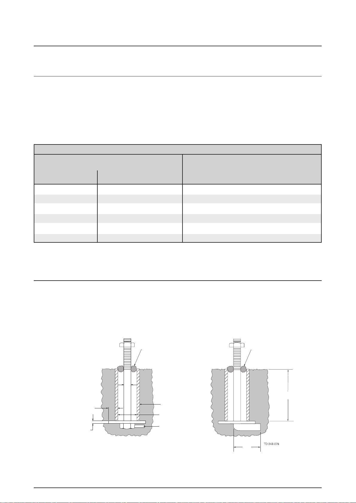
The drawing above shows two typical methods for foundation bolt retaining. The sleeve allows for “slight” lateral movement
of the bolts after the foundation is poured. Rag or waste paper can be used to prevent the concrete from entering the sleeve
while the foundation is poured. A minimum of 14 days us normally required to allow the curing of the concrete prior to pump
unit installation.
Waste put around bolt
before pouring concrete Foundation surface left
through to anchor ground
One D
Minimum
One-half D
Minimum
Sleeve
3D
Lug welded to
bolt head
10D
4D
D