SSP Jet-Kleen JK-FFP1 User manual

J
ET-
K
LEENTM
Safe Personnel Blow-Off Gun & Drying System
Installation & Operation Manual
MODELS:
JK-FFP1
JK-FFP1V
JK-FFP2
JK-FFP2V
JK-WTB1F
JK-WTB1FV
JK-WTB2F
JK-WTB2FV
SPECIALIZED SAFETY PRODUCTS
A Division of The A.W.T. World Trade Group
p
S
S
WALL-MOUNT UNIT
PORTABLE UNIT
OPTIONAL
STAINLESS-STEEL
ENCLOSURE
A Product of

Overview & Features ...............................3
Safety Precautions .................................4
Owner’s Responsibilities ..........................4
Portable Jet-Kleen Unit ...........................4
Electrical Safety ..............................4
General Safety ................................4
Wall-mounted Jet-Kleen Unit ......................4
Electrical Safety ..............................4
General Safety ................................4
Replacement Parts ...............................4
Installation & Setup ...............................5
Gun Assembly Attachment ........................5
Filter Replacenet ................................5
Timer Control ....................................5
Variable Speed Control ..........................6
Replacement Parts .............................6
Replcament Parts Photos ........................7
Technical Information ..............................7
Models and Specifications ....................... 8
Government Regulations .........................8
PSI Specifications ...............................8
Electrical Specifications ..........................8
Space Requirements .............................8
Portable models ..............................8
Wall models .................................8
Velocity .......................................8
Noise Level .....................................8
Warranty ....................................... 10
SPECIALIZED SAFETY PRODUCTS
A Division of The A.W.T. World Trade Group
Chicago, IL 60641 USA
p
S
S
Thank you for choosing the Jet-Kleen™ Blow-Off Gun to safely handle your
personnel dust-off and drying and cleaning of equipment and components.
This Installation & Operation Manual will help you get the most out of your Jet-
Kleen Blow-Off Gun by guiding you through proper setup and operation of the unit.
If you have any questions, our technical support experts are ready to help you.
Just call us at 800.444.PART, Monday through Friday, 8 a.m. to 5 p.m. (Central
Standard Time) within the U.S. and 773.725.4900 outside the U.S. We also welcome
the opportunity to fill your other equipment needs and to meet your ongoing supply
requirements.
Thank you for choosing Specialized Safety Products. We look forward to serving
you again in the near future.
Sincerely,
Michael Green
President
Table of ConTenTs
SPECIALIZED SAFETY PRODUCTS A Division of The A.W.T. World Trade Group
p
S
S
4321 N. Knox Ave., Chicago, IL 60641 USA 773.777.7100 • Fax:773.777.0909
sales@specializedsafetyproducts.com www.specializedsafetyproducts.com
Jet-Kleentm 2 Installation & Operation Manual
A Product of
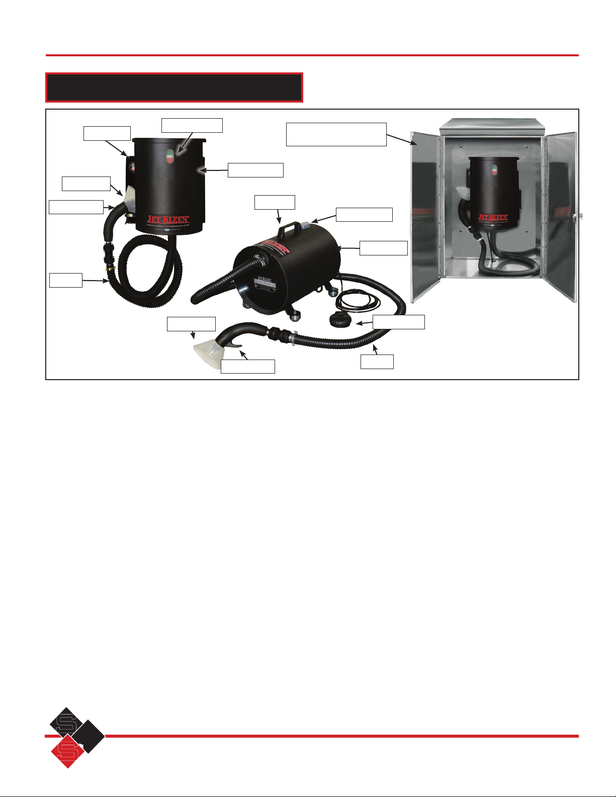
Figure 1. Jet-Kleen units and major components.
overview & feaTures
Foot pedal
Blower unit
Handle
Hose
STANDARD FEATURES
All Models
• Blower-driven system delivers high volume of air at safe
3.0 psi (206.8 mBar)
• Flexible hose allows easy control of air gun nozzle
• Chip guard–acts as safety shielding, protecting the user
from dangerous blow-back particles
• Heavy-duty plastic body ensures rugged performance
• Heat-resistant hose retains flexibility in all workplaces
• Stainless-steel clip for easy removal of hose from unit
• Foam-insulated interior ensures low noise levels –
maximum 78 dB (A)
• Can be aimed directly at the body
• Removes dust, fibers, water and powders from work
clothes and machinery
• Low operating cost
• 115 V and 240 V, 50/60 Hz units available
Portable Models
• Extra long 96” (243.8 cm) hose
• Foot pedal
Wall-mount Models
• Timer for adjusting time unit remains on
• Holster holds nozzle when not in use
• 56” (142 cm) hose
OPTIONS AND ACCESSORIES
• Variable speed controller
• Additional blow gun assembly
• Stainless-steel enclosure for outdoor mounting
• Timer for adjusting time that unit remains on (for
Portable Model; standard on Wall-Mount Model)
On/off button
Gun assembly
On/Off button
Hose
Chip guard
Chip guard
Wall mount Optional stainless-steel
outdoor enclosure
Blower unit
Gun assembly
SPECIALIZED SAFETY PRODUCTS A Division of The A.W.T. World Trade Group
p
S
S
4321 N. Knox Ave., Chicago, IL 60641 USA 773.777.7100 • Fax: 773.777.0909
sales@specializedsafetyproducts.com www.specializedsafetyproducts.com
©2010 Specialized Safety Products. No part of this literature may be reproduced without written permission. Specifications subject to change without notice. #MAN-AWT-JETKLN 07/10
Installation & Operation Manual 3 Jet-Kleentm
A Product of

safeTy PreCauTions
OWNER RESPONSIBILITIES
To ensure safe and trouble-free operation of this equip-
ment, the operator must have a thorough understanding of
safety precautions and operating procedures. Therefore, it
is the responsibility of the equipment owner to ensure that
every operator of this equipment:
1. Reads the Safety Precautions section of this manual
and understands the instructions prior to operating
this equipment.
2. Reads the operating section of this manual and under-
stands all operating procedures prior to operation.
3. Observes the fundamental regulations pertaining to
workers’ protection and accident prevention.
4. Observes additional rules and regulations in effect at the
equipment owner’s place of business.
Once trained, equipment operators should be continually
evaluated to ensure they fully understand safety precautions and
operating procedures.
Following simple safety guidelines can further reduce
hazard risks.
CAUTION
Please read all information regarding safety
precautions. Failure to follow these procedures
may void your warranty.
SAFETY
1. Check the AC cable for nicks and cuts (regularly check
the cable to ensure it is in good condition).
2. Ensure that the correct supply voltage is available before
switching on the unit.
3. It is recommended that the unit be connected to an elec-
trical supply that is surge protected and in compliance
with local codes.
4. The unit is fitted with a standard three-prong plug with a
15A circuit breaker.
5. There are no serviceable parts in the fan unit.
6. Do not pull the portable unit by the electrical cable or
the hose.
7. Be sure the voltage being used corresponds with the volt-
age on the machine parts. The standard motors are 115
V, 1 Ph, 50/60 Hz and 240 V, 1 Ph, 50/60 Hz.
General Safety
1. The On/Off switch for both units is located on the cylin-
drical enclosure at the end furthest from the blower
hose. Press the RED button for OFF and the GREEN but-
ton for ON.
2. Be sure the portable unit stands level on the four bottom
feet.
3. If the unit has been fitted with a speed controller, adjust
the speed to your desired level while the unit is off.
4. Do not remove any guarding or the flexible hose at any
time. Do not allow objects to pass through the guard
while the fan is rotating.
5. Always switch the unit off at the main electrical supply
and remove the plug before cleaning the Jet-Kleen. Do
not use a pressure washer or steam washer to clean the
unit.
6. Eye protection should be worn at all times while
operating the unit.
REPLACEMENT PARTS
This unit was designed and engineered with operator
safety and maximum performance as primary objectives.
Substitution of non-OEM parts may jeopardize safety and/or
performance and void your warranty.
insTallaTion & seTuP
The wall mount unit should be located where it will be
most convenient for use, such as an entry/exit point.
Mount the unit with six screws through the holes on the
wall mount (Figure 1, page 3). The bottom (hose end) of the
unit should be about 51-52” above the surface.
The portable model should be placed so the four legs
are in contact with a flat surface.
Both units should be plugged into an appropriate
grounded outlet.
Press the green button on the on/off switch to operate
the Jet-Kleen. The red button shuts it off.
Figure 2. With locking ring unscrewed (as pictured) pull quick-release fitting
toward hose.
Locking ringQuick-release fitting
Gun
assembly
Swivel connector
SPECIALIZED SAFETY PRODUCTS A Division of The A.W.T. World Trade Group
p
S
S
4321 N. Knox Ave., Chicago, IL 60641 USA 773.777.7100 • Fax:773.777.0909
sales@specializedsafetyproducts.com www.specializedsafetyproducts.com
Jet-Kleentm 4 Installation & Operation Manual
A Product of

Gun Assembly Detachment
To detach the gun assembly follow these instructions:
1. Rotate the locking ring on the swivel connector (Figure
2, page 4) counterclockwise 180° until it clicks.
2. Pull the quick-release fitting toward the hose away from
the gun assembly.
3. Twist and pull out the gun assembly.
Gun Assembly Attachment
To attach the gun assembly, follow these instructions:
1. Leave the locking ring open (unscrewed) as shown in
Figure 2. If the locking ring is in the closed position, fol-
low Step 1, above.
2. Push the new gun firmly into place.
3. Close the locking ring by rotating it
180° back to its
original position.
Follow similar procedures when replacing the
hose by using the locking ring and quick-release
fitting on the hose end of the swivel connector.
Filter Replacement
The filter, timer control and optional variable speed
control are located under the top cover of the wall-mounted
Jet-Kleen and on the non-hose end of the portable unit.
Replacing the filter is recommended at least every six
months, although operating conditions could warrant
replacement much earlier.
To access the filter assembly on the wall-mount unit,
remove the three screws on the top cover (Figure 4) using a
5/32” hex wrench. Pull out the filter and replace with new.
Replace the top cover and three hex-head screws.
Procedures are the same for a portable unit except there
is no cover to be removed.
Cover Screws Filter
Timer Control Plug
Variable Speed
control Plug
Filter Cover
Figure 4. Location of cover screws, (left-wall-mount unit only);
filter assembly, (right).
iMPorTanT
To PrevenT overHeaTinG
anD PerManenT DaMaGe
Do noT run
uniT More THan
3 ConTinuous
Hours
TIMER CONTROL
The Jet-Kleen features a timer control that allows you to
set the length of time it will operate before shutting off auto-
matically. Timing is set with two dials located inside the top
of the unit.
To access the timer, remove the three screws on the
top cover (Figure 4) and lift off the cover. Carefully pry off
the plug located on the unit, using a small screwdriver. The
timer controls (Figure 5) are located under the plug. A small
Phillips screw driver is required to turn the dials.
Timer Control
Figure 5. Location of timer control, (left-wall-mount unit only);
Timer control, (right).
Time
Increment
Time
Multiplier
The smaller dial sets the main increment. Options are
1, 3, and 10 minutes; 1, 3, 10 and 60 hours; and 1, 3, and 10
seconds. The larger dial is the multiplier applied to the incre-
ment, ranging from 1 to approximately 0.05.
SPECIALIZED SAFETY PRODUCTS A Division of The A.W.T. World Trade Group
p
S
S
4321 N. Knox Ave., Chicago, IL 60641 USA 773.777.7100 • Fax: 773.777.0909
sales@specializedsafetyproducts.com www.specializedsafetyproducts.com
©2010 Specialized Safety Products. No part of this literature may be reproduced without written permission. Specifications subject to change without notice. #MAN-AWT-JETKLN 07/10
Installation & Operation Manual 5 Jet-Kleentm
A Product of

INCREMENT
SETTING
APPROXIMATE
RANGE
1m 3 seconds - 1 minute
3m 9 seconds - 3 minutes
10m 30 seconds - 10 minutes
1h 3 minutes - 1 hour
3h 9 minutes - 3 hours
10h 30 minutes - 10 hours
60h 3 hours - 60 hours
1s 50 milliseconds - 1 second
3s 150 milliseconds - 3 seconds
10s 500 milliseconds - 10 seconds
Figure 6. Timer control settings.
To set the timing, select the increment to be used then
the multiplier to be applied. For example, to set timing at 30
minutes, select an increment of one hour (1h) and a multi-
plier of .5 (located at the hash mark midway between .6 and
.4). This would yield 1 hour x 0.5 = 0.5 hours = 30 minutes.
Factory default is 60 seconds.
To operate the Jet-Kleen press the green START button.
The unit will run until the preset time elapses or the red
STOP button is pushed.
iMPorTanT
To PrevenT overHeaTinG
anD PerManenT DaMaGe
Do noT run
uniT More THan
3 ConTinuous
Hours
VARIABLE SPEED CONTROL (OPTION)
The remaining plug covers the Variable Speed Control
adjustment (Figure 7). Carefully pry off the plug located on the
unit, using a small screwdriver. Turn adjustment screw clock-
wise to increase speed, counterclockwise decreases speed.
Variable Speed Control
Figure 5. Location of Variable Speed Control, (left-wall-mount unit only);
Variable Speed Control, (right).
rePlaCeMenT ParTs
CATALOG # DESCRIPTION
JK-GA Gun Assembly" Nozzle W/Chip Guard Included
JK-CG Chip Guard
JK-NO Nozzle only
JK-WMH Wall Mount Hose
JK-SC Connector Only – For Hose Unit
JK-FE Filter Assembly
JK-FP Foot Pedal
JK-FMH Portable Hose Only
JK-VM Vacuum Motor 115V
JK-VM-240 Vacuum Motor 240V
JK-TRS Tamper Resistant Screws (Pkg of 15)
JK-VSC Vacuum Switch - 2 Stage - Foot Pedal
JK-COS Contactor
JK-TIMER Timer
JK-SSpeed Control
JK-TOOL Special Jet-Kleen Unit Opening Tool (Bit only)
JK-OS On/Off Switch
SPECIALIZED SAFETY PRODUCTS A Division of The A.W.T. World Trade Group
p
S
S
4321 N. Knox Ave., Chicago, IL 60641 USA 773.777.7100 • Fax:773.777.0909
sales@specializedsafetyproducts.com www.specializedsafetyproducts.com
Jet-Kleentm 6 Installation & Operation Manual
A Product of

rePlaCeMenT ParTs
JK-GA
Gun Assembly
With Chip Guard/Nozzle JK-CG
Chip Guard
JK-NO
Nozzle JK-WMH
Wall Mount Hose
(56"/142 cm)
JK-SC
Connector
JK-FE
Filter Assembly JK-FP
Foot Pedal
JK-FMH
Portable Hose
(96"/244 cm)
JK-VM
Vacuum Motor 115V
JK-TRS
Tamper-Resistant Screws
Package of 15 JK-VSC
Vacuum Switch
2 Stage - for Foot Pedal
JK-COS
Contactor
JK-TIMER
Timer
JK-S
Speed Control
JK-TOOL
Special Jet-Kleen Unit Opening Tool
(Bit only) JK-OS
On/Off Switch
Not Pictured: JK-VM-240 Vacuum Motor 240V (Similar to JK-VM);
SPECIALIZED SAFETY PRODUCTS A Division of The A.W.T. World Trade Group
p
S
S
4321 N. Knox Ave., Chicago, IL 60641 USA 773.777.7100 • Fax: 773.777.0909
sales@specializedsafetyproducts.com www.specializedsafetyproducts.com
©2010 Specialized Safety Products. No part of this literature may be reproduced without written permission. Specifications subject to change without notice. #MAN-AWT-JETKLN 07/10
Installation & Operation Manual 7 Jet-Kleentm
A Product of

CATALOG NUMBER UNIT TYPE ON/OFF HOSE SPEED
CONTROL
TIMER ELECTRICAL
SPECIFICATIONS
JK-FFP1 Portable On/off switch/foot pedal 96” (244 cm) No Option 115 V, 1 Ph, 50/60 Hz
JK-FFP1V Portable - variable speed On/off switch/foot pedal 96” (244 cm) Yes Option 115 V, 1 Ph, 50/60 Hz
JK-FFP2 Portable On/off switch/foot pedal 96” (244 cm) No Option 240 V, 1 Ph, 50/60 Hz
JK-FFP2V Portable - variable speed On/off switch/foot pedal 96” (244 cm) Yes Option 240 V, 1 Ph, 50/60 Hz
JK-WTB1F Wall-mount On/off switch 56” (142 cm) No Yes 115 V, 1 Ph, 50/60 Hz
JK-WTB1FV Wall-mount - variable speed On/off switch 56” (142 cm) Yes Yes 115 V, 1 Ph, 50/60 Hz
JK-WTB2F Wall-mount On/off switch 56” (142 cm) No Yes 240 V, 1 Ph, 50/60 Hz
JK-WTB2FV Wall-mount On/off switch 56” (142 cm) Yes Yes 240 V, 1 Ph, 50/60 Hz
MODELS AND SPECIFICATIONS
TeCHniCal inforMaTion
GOVERNMENT REGULATIONS
The Jet-Kleen has been designed in accordance with the fol-
lowing directives:
EN55014-1 EMC Directive (Emissions)
EN55014-2 EMC Directive (Immunity)
EN60335-2-69 Low Voltage (Electrical Safety Testing)
EN61000-3-2 EMC - Limits for harmonic current emissions
EN61000-3-3 EMC - Limits of voltage changes, fluctuations
and flicker in public low-voltage supply systems
PSI SPECIFICATIONS
112.7 cubic feet of air per minute at 3.0 psi.
More than 3 psi is illegal in Europe. In the
USA, we conform to OSHA Standard number
1910.242 (B).
ELECTRICAL SPECIFICATIONS
See chart above
SPACE REQUIREMENTS
Portable Models
• Weight: 18.6 lbs. (8.4 kg)
• Dimensions: 16.6”L x 11.3”W x 13.7”H
(42.2 x 28.7 x 34.8 cmcm)
Wall Models
• Weight: 18.6 lbs. (8.4 kg)
• Dimensions: 16”L x 14”W x 11.9”H
(40.6 x 35.6 x 30.2 cm)
VELOCITY
22,000 feet per minute
NOISE LEVEL
Below 78 dB (A)
SHIPPING INFORMATION
Both Models
• Weight: 23 lbs. (8.4 kg)
• Dimensions: 23”L x 16”W x 17”H
(58.4 x 40.6 x 43.2 cm)
WARRANTY
Specialized Safety Products/A.W.T. equipment is warranted against defects in workmanship and materials for a period of one (1) year or 2,500 hours
running time, annually, from the shipping date of the equipment from A.W.T. World Trade, Chicago, IL 60641. Warranties are not included for any product
or machine invoice that remains unpaid according to the Sales Agreement/Quotation conditions.
Specialized Safety Products/A.W.T. does not fully cover expendable parts, such as filters, for this limited warranty. Some parts may be considered under a
prorated warranty.
Specialized Safety Products/A.W.T.’s warranty does not provide for failure of parts or components resulting from misuse or lack of maintenance.
Specialized Safety Products/A.W.T. is not responsible for installation or replacement of any defective part. Service labor, travel cost and sustenance charges are
the responsibility of the customer on all defective parts. Removal or installation, if requested, is billed at the prevailing service rates.
Any part determined to be defective, in workmanship and material, under this limited warranty period will be repaired or replaced, at our option, without
charge, when returned within 30 days from the date the Return Authorization was issued. Specialized Safety Products/A.W.T. is not obligated to pay freight
costs. Customers must obtain a return authorization number from our Customer Service Department or service manager before returning any defective part. The
consumer must return parts via prepaid postage or prepaid freight to the following address:
A.W.T. World Trade Inc.
4321 N. Knox Ave.
Chicago, IL 60641 USA
Consequential damages, lost time, material loss, inconvenience or contingent liabilities are not covered by this warranty. We specifically make no other warranties,
expressed or implied, other than the above Limited Warranty.
This manual suits for next models
7
Table of contents
Other SSP Vacuum Cleaner manuals


