2
Anwendung
Die Farb-CCD-Video-Kamera ist für
die Montage im Aussenbereich ge-
eignet. Sie ist wettergeschützt, mit
einem Sonnendach und thermo-
statisch geregelter Heizung.
Sockelgehäuse mit Kugelkopf und
innenliegender Kabelführung. Die
Anschlussleitungen für die Ver-
sorgung und die Koaxleitung sind
steckerfertig montiert; ca.10 cm
lang. Befestigungsmaterial und
Inbusschlüssel liegen der Kamera
bei. Die Einstellung von Zoom und
Focus ist über Tasten direkt an der
Kamera möglich.
Elektrische Spannung
Einbau, Montage und Service-
arbeiten elektrischer Geräte
dürfen ausschließlich durch eine
Elektro-Fachkraft erfolgen.
•Bitte lesen Sie diese Produktinfor-
mation, bevor Sie die Kamera in Be-
trieb nehmen.
•Betreiben Sie die Kamera nicht
außerhalb der angegebenen Tem-
peratur-, Feuchtigkeits- oder Span-
nungsgrenzwerte.
•Bei der Verlegung der Anschluss-
kabel ist darauf zu achten, dass
diese nicht belastet, geknickt oder
beschädigt werden.
Folgende Einbausituationen müssen
unbedingt vermieden werden:
•direktes Gegenlicht
•direkte Sonneneinstrahlung
•Bildhintergrund mit großer
Helligkeit
•stark reflektierende Wände auf der
gegenüberliegenden Seite der
Kamera
•Leuchten bzw. direkte Lichtquellen
im Blickfeld der Kamera
Elektrostatische Aufladung
Durch elektrostatische Aufladung
kann bei direktem Kontakt mit der
Leiterplatte das Gerät zerstört
werden. Vermeiden Sie daher ein
direktes Berühren der Leiterplatte.
Lieferumfang
•KA/WG 950-...
• 3 Kreuzschlitzschrauben 5 x 50
• 3 Dübel D = 6 mm
•Inbusschlüssel Größe 3
•Zugentlastung mit 2 Schrauben
• 8 Verschlussstopfen
•diese Produktinformation
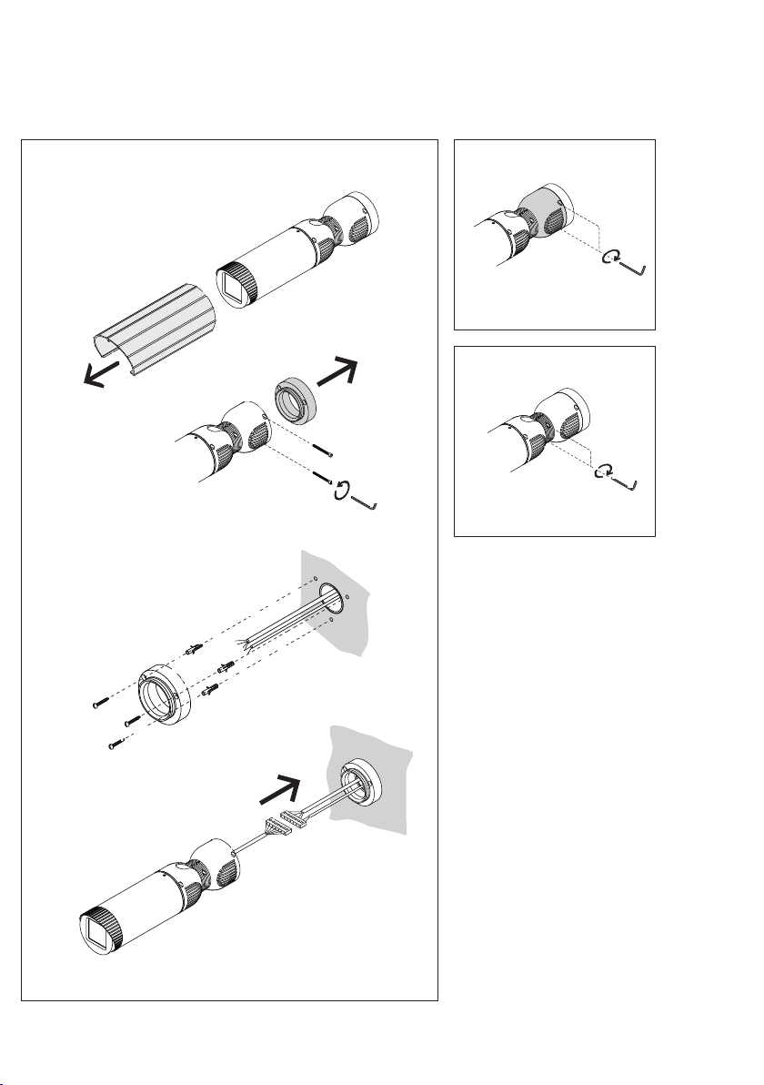
Montage
1-Sonnendach abnehmen.
-Befestigungsschrauben des
Montagesockels entfernen.
-Montagesockel an der Wand
montieren. Bohrschablone auf der
Klappseite verwenden.
-Versorgungsleitung und Koaxkabel
der Hausinstallation am 6-poligen
Steckverbinder der Kamera anschlie-
ßen und die Überlänge der An-
schlussleitung im Sockelgehäuse
verstauen. Mit der Zugentlastung
das Installationskabel am Kamerafuß
festschrauben.
2Kamera auf dem Montagesockel
aufsetzen, die Befestigungsschrau-
ben mit wenig Druck ansetzen und
festschrauben.
3Entsprechende Feststellschrauben
lösen, Kamera auf den Aufnahmebe-
reich ausrichten und fixieren.
Deutsch
Montage
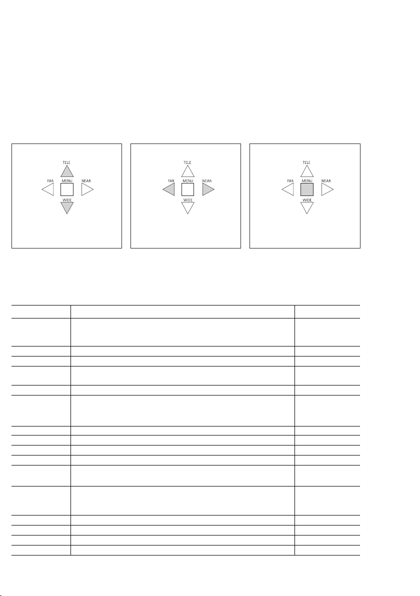
Zoom und Fokus einstellen
4Durch Eindrehen der Maden-
schraube Kameragehäuse öffnen
(rechtsdrehend) und Schutzgehäuse
abnehmen.
5Mit den Tasten auf der Rückseite
der Kamera werden Zoom und Focus
eingestellt. Diese Einstellungen kön-
nen direkt an der Kamera ausgeführt
werden.
a) TELE/WIDE
Einstellung des optischen Zoom-
bereich
b) FAR/NEAR Einstellung des Focus
c) MENU Auswahl von
Menüfunktionen in der OSD-
Anzeige
d) BNC-Anschluss, Videosignal 1Vss
e) RS485-Schnittstelle für
Ansteuerung über PC
Weitere Einstellungen
Weitere Einstellungen der Kamera
sind über ein OSD-Bildschirm-Menü
(On-Screen-Display) möglich. Um die
Einstellungen vorzunehmen, muss
das Videosignal der Kamera an
einem Monitor angeschlossen
werden. Auf dem Monitor ist das
Menü der Kamera zu sehen. Die
einstellbaren Menüpunkte sind auf
den beiden nächsten Seiten zu
sehen.
6Gehäuse schließen, verschrauben
und Sonnendach über das Kamera-
gehäuse schieben. Die sichtbaren
Inbusschrauben können mit den
beiliegenden Verschlussstopfen
abgedeckt werden.
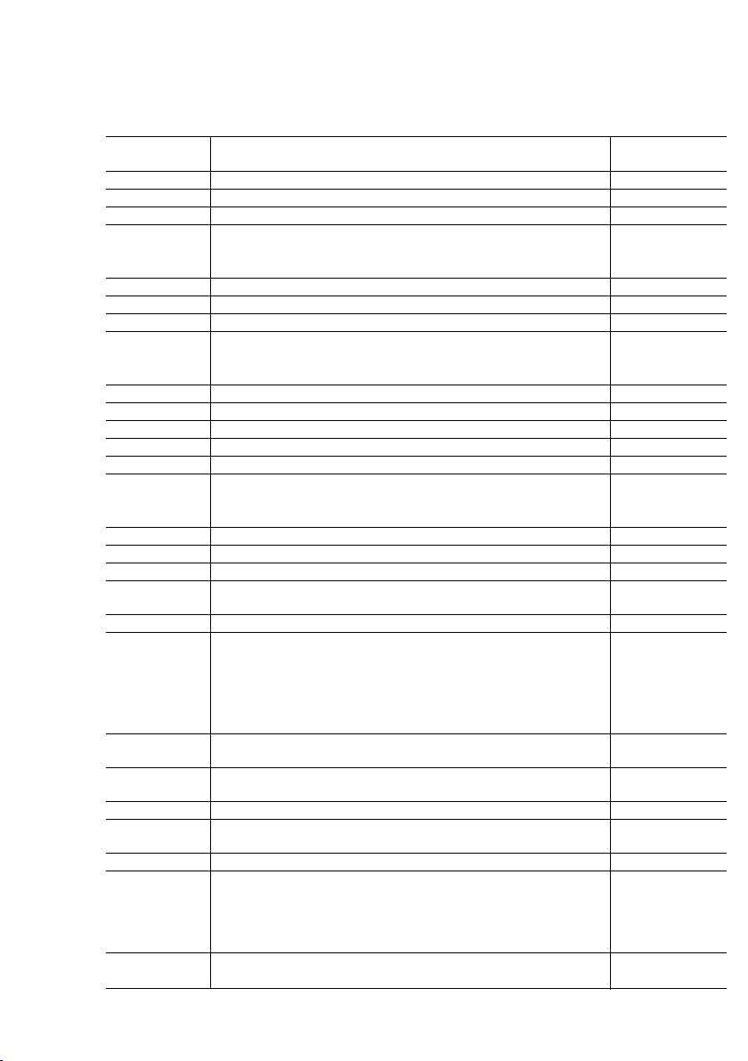
Klemmenbelegung
Schwarz =-Versorgung
Rot = + Versorgung
20 – 30 V DC
Braun/
Orange = Lb, Hz Versorgung für
die Heizung 12V AC
Koax =
S/L Schirm/Leiter