SSSI Black4Neo User manual

0
Standalone DVR
USER’S MANUAL
DVR-Black4Neo
DVR-Black800Neo
DVR-Black1600Neo
Revision date : Oct 2006

1
•Contents
• Chapter 1. Specification & System organization
1. Product Contents List -------------------------------------------------------- 3
2. System Organization --------------------------------------------------------- 4
•Chapter 2. Product Description
1. DVR-1600Neo / 800Neo Front Panel--------------------------------------------- 5
2. DVR-1600Neo / 800Neo Rear Panel ----------------------------------------------- 7
3. DVR-Black4Neo Front Panel-----------------------------------------------------8
4. DVR-Black4Neo Rear Panel ---------------------------------------------------- 9
5. Remote Controller -------------------------------------------------------- 10
•Chapter 3. Display
1. System Power ON ---------------------------------------------------------- 11
2. Screen View Selection ------------------------------------------------------ 12
3.Display Mode ------------------------------------------------ 12
4. PTZ/FOCUS Control -------------------------------------------------------- 13
5. System Power OFF --------------------------------------------------------- 13
•Charpter4. Search
⊙ Go to Search Mode --------------------------------------------------------- 14
1. Search by Date/Time ------------------------------------------------------- 14
2. Search by Event ----------------------------------------------------------- 15

2
•INDEX
•Chapter 5. SETUP
⊙ Go to Menu -------------------------------------------------------------- 16
⊙ Go to System Setup -------------------------------------------------------- 16
1. Display ------------------------------------------------------------------ 17
2. Camera ----------------------------------------------------------------- 21
3. Sound ------------------------------------------------------------------ 22
4. System ------------------------------------------------------------------ 25
5. Event/Sensor ------------------------------------------------------------- 30
6. Disk Management ---------------------------------------------------------- 31
⊙ Go to Record Menu -------------------------------------------------------- 34
1. Recording Operation -------------------------------------------------------- 34
2.Timer/motion setup ---------------------------------------------- 35
3. Alarm Record Schedule ----------------------------------------------------- 34
4. Panic setup ------------------------------------------------------- 37
⊙ Go to Archiving ----------------------------------------------------------- 38
1. CD-RW and USB Back up --------------------------------------------------- 38

3
1. Product contents List
Please Confirm the Contents When open Package.
①Basic Contents
Remote Controller
User’s Manual Remote Client
Program Install CD
AAA Battery X 2
Power Cable
② Option Contents
HDD
CD-RW USB Memory
1. Specification & Organization
4
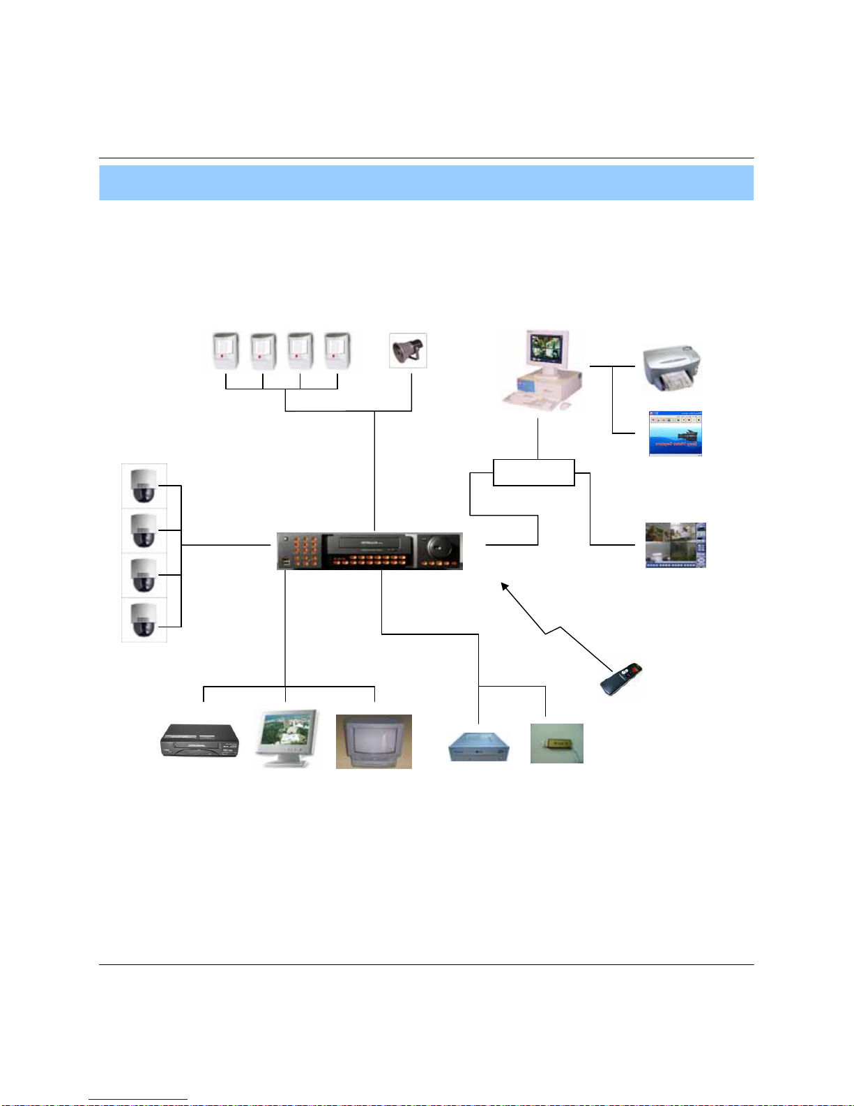
2. System Organization
NETWORK
Camera #1-8(16)
Alarm Sensor #1-8(16) Relay Out
VCR VGA
Monitor AV Monitor
Remote Client PC Image Printer
Video In
Video Out
TCP/IP
Alarm Input/Out
Remote
Controller
CD-RW
(It is not supported on DVR-Black4Neo)
Backup
AVI Backup
WEB Client
USB
1. Specification & Organization

5
2. Description (DVR-Black800Neo/1600Neo)
• Channel Selection Button is Prior to DISPLAY.
• When Remote Controller Sensor Input is Blocked by Something, it Cause 1
Remote Controller do NOT Work Properly.
• When Press any Button, it Operate with Beep Sound.
Tip
1. Front Panel
1234
11
12
9
8
765 10
POWER : System Power On/Off
SHORTCUT : Shortcut button for convenience.
CD/DVD RW : Back up image to CD/DVD RW
HOLD : Hold Current Jog/Shuttle position
RETURN : Cancel/Deselect/Return to previous screen
Direction / Navigation Button : UP/DOWN/LEFT/RIGHT
ENTER : Confirm/ Select next screen
CHANNEL Select button : Select Channel or Input Password.
FOCUS : Adjust Focus (Near/ Far) or Reverse Play /Rewind
PAUSE : Pause playback
IRIS : Adjust Iris (Open/Close) or Forward Play / Fast forward
Jog shuttle : Outer wheel – variable REW or FF : Inner wheel – scroll frame – by frame while paused
1
2
3
4
10
11
9
8
7
6
5
12

6
2. Description
* Shortcut button
123
4
9
8
7
6
5
DISPLAY : Select Screen Division Mode or Rotation Mode.
SEQ : Select sequence screen mode.
PANIC : Urgent Recording as setup.
ZOOM : Digital zoom on Live or Playback image
LOCK : Front Panel Lock Button (Default password: 1234)
When locked, “LOCK” is displayed on screen. Press lock button to unlock.
ARCHIVE : Go to archiving setup menu. (Default password : 1234)
PTZ : Go to Camera PTZ Control.
SETUP : Go to System Setup.
SEARCH : Go to Search Mode.
1
2
3
4
9
8
7
6
5
* FOCUS / IRIS button
FOCUS IRIS
1 2 3 4
1
2
3
4
NEAR : Set camera focus (Near & Far) or Reverse Play/Rewind.
FAR : Set camera focus far.
CLOSE : Close camera iris.
OPEN : Open camera iris.
7
• Do not power on the unit all cable connections have been made.
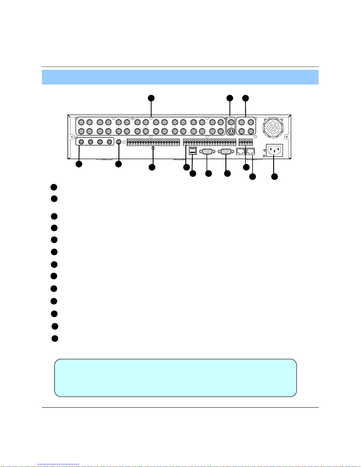
2. Rear Panel
2. Description
Tip
1
2
3
4
7
6
5
Video IN / Loop : BNC Video Input Port/ Loop Output (1-8/16)
11
12
9
8
10
13
Monitor out : BNC Main Monitor Output.
SVHS : S-Video Main Monitor Output.
Spot #1 ~ #4 : 4x BNC Output to individually – Sequenced Spot Monitors
Audio In : 4 x RCA Audio Line Input Terminal
Audio Out : RCA Audio Line Out Terminal
Alarm : 8/16 x Input TTL Alarm/Sensor Input Terminal
USB : USB port for use the USB memory stick and USB HDD Backup.
VGA OUT : VGA Main Monitor Output (to a computer Monitor)
RS-232C : Serial Configuration Port for Program Debugging.
RS-485 : Serial Interface for PTZ device connection and control
Ethernet (TCP/IP) : 10/ 100 Ethernet LAN/WAN connection (for Remote Access and configuration)
POWER : Power Cable connection.
Relay : 8/16 x Relay Output Terminal
12
98 10 13
1 2 3
476
511

8
1. Front Panel
• Power Button is Soft Style to Prevent System Failure by Wrong Operation.
• Channel Selection Button is Prior to SCR Mode.
• When Remote Controller Sensor Input is Blocked by Something, it Cause
1Remote Controller do NOT Work Properly.
• When Press any Button, it Operate with Beep Sound.
•In Case of CD-RW, the Real Appearance will be Differ from the above Picture
1Depends on its Model.
2. Description (DVR-Black4Neo)
Tip
1 2 3 4
7
65
11 1298 10 13 1415
CD-RW : CD-RW Device for Backup.
Channel Selection Button : Select Channel or Input Password.
Led Indicator : Indicate Present System Status Information.
( PWR: System On/Off, REC: Record On/Off,
ALARM: Alarm Sensor Detection Status, NET: Client Network Connection Status, )
Search Controller : Searching Recorded Data or Control Menu & PTZ/FOCUS.
HOLD : Hold Jog dial.
JOG dial
Eject : Eject CD
MENU : Go to System Menu.
SEARCH : Go to Search Mode for Searching Data.
SCR MODE : Select Screen Division Mode or Rotation Mode.
PTZ/FOCUS : Go to Camera PTZ/FOCUS Control.
RETURN : Cancel Setup or Return to Previous Mode.
ENTER : Apply Changing Setup.
Remote Controller Sensor Input.
USB Port: USB port for use the USB memory stick and USB HDD Backup
1
2
3
4
7
6
5
11
12
9
8
10
13
14
15
9
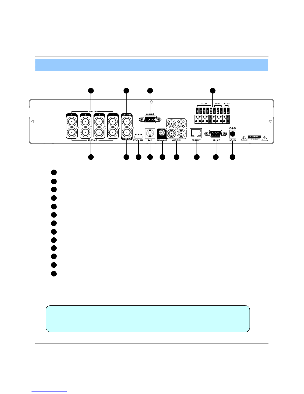
2. Rear Panel
2. Description
• When System Installation, Please Install under System Power OffStatus.
• Please Use Specific Adaptor when Power Supply.
Tip
2 4 75 1298 10 13
1 3 6 11
Video In : BNC Port for Connection of DVR & Camera. (4 Camera Connectable)
Loop Back : Output DVR Camera Video to Loop Back Port. (4 BNC Port)
Monitor Out : Output DVR Video to AV Monitor.
Spot Out : Output Spot-out Video to AV Monitor.
NTSC/PAL : Select NTSC or PAL Type.
VGA OUT : Output Video to a Computer Monitor by Connected VGA (Option)
SVHS : Output Video by Connected SVHS.
Audio Out : Output Audio Data.
Audio In : Audio Input Terminal Related with #1~4 Camera.
Ethernet (TCP/IP) : Port for Cross cable. (Possible to Remote Surveillance.)
Alarm/Relay/RS-485 : Connect Port for Sensor, Relay, & PTZ.
RS-232C : Connect Port for Program Debug.
DC Power Input : Power Supply by DC 12V Adaptor.
1
2
3
4
7
6
5
11
12
9
8
10
13

10
POWER
System
ON/OFF
MENU : Open System Setup Menu
RETURN
Cancel /
Deselect
Previous Screen
ENTER : Apply / Select /Go to Next Sereen
Channel Selection Buttons
Change Display
Mode
Search Menu PTZ/IRIS Mode
• There are buttons on the controller that are unused, and their descriptions have been omitted.
• Every Button on the controller will function the same as its corresponding button on the Front Panel
• Remote Controller will only work when used within line-of-sight of the IR remote sensor on the DVR.
※ If there are many DVRs within line-of-sight of the controller, they will all respond to the controller.
Navigation Buttons : Used for Playback
Control, Menu Navigation, and PTZ/Focus
Control
3. Remote Controller
2. Description

11
1. System Power ON
• Press power button to start system.
• After Checking Hard Disk, display mode is shown.1
• Initial Screen View Mode is Quad Division Mode and
Recording Mode.
<Picture of Power On after Finishing Installation>
3. Display
• Check System status LEDs
Power : Indicates System (On/Off)
Record : Indicates Recording (On/Off)
Network : Indicates Network/LAN Client connection Status
Tip
CAMERA
2005/01/01
00:00:00
• Each Channel Indicates Camera Name & Recording Status.
• Present Time & Date shown on Status Bar at a bottom of screen.

12
3. Display Mode
• User can select from a variety of multi-screen display modes (1/4/6/8/9/13/16ch)
• The initial display mode is set to either 8ch or 16ch mode.
3. Display
2. Screen View Selection
• Select One Channel using the channel selection buttons (1-8/16).
• Use the display button to change the multi-channel Display mode.
• Press channel selection button twice to view the channel on full screen.
When this unit is connected with a remote client PC, a
Network status icon will appear on the Status Bar
• This icon indicates the current network conditions
- Green: Network is connected and stable.
- Blue: Network is connected, but is unstable.
- Red: Network is very unstable.

13
3. Display
• Each PTZ function is manipulated by using a button on the Front Panel or on the Remote controller.
• Some of the notations on the PTZ menu are abbreviated. (P: Pan, T: Tilt, Z: Zoom, F: Focus, I: Iris)
• All of the functions on the PTZ menu are labeled along with the Front Panel/ Controller button that control it.
4. PTZ/FOCUS Control
• Control Camera Movement of PTZ (Pan/Tilt/Zoom) devices.
• Press PTZ Button to switch into PTZ mode. (Status Bar is replaced by PTZ controls)
5. System Power Off
• Press power button to power system off.
• Input password and press enter to shutdown system.
• Don’t disconnect AC power without completing shutdown.
• System Log-On User Account Types are ‘Administrator’, ‘Manager’, ‘User’
Administrator: Access All Function (Power On, Shutdown, Setup, Search, Backup)
Manager: System Power On, Live View, Search, Playback
User: System Power on and Live View
Tip

14
2004/01/01
00:00:00 >
⊙ Go to Search Mode
• Press search button and Log-In.
(as administrator or manager )
• Use directional keys to navigate search menu.
• To open/ advance each sub menu, Press enter
• To return to a previous menu screen, Press return.
( Repeatedly pressing return will exit out of all menus.)
1. Search by Time
- Search by a recorded Date/ Time
① Move cursor to select the date on the calendar.
② Press enter to open selected date.
③ Recorded timeline will appear.
④ Move cursor to the specific time, and press enter.
(The timeline is divided into 15 minutes segments)
⑤ Menu will be hidden from view, and playback will
start playing from the selected date/ time forward.
• The recorded date & time is shown on the status bar.
• The current playback mode (Play, Pause, FF, REW)
is indicated with on icon on the bottom-right of the screen.
• The channel selection and display buttons will work the
same as in live view mode, setup, PTZ and archiving
buttons don’t work in the playback mode.
4. Search

15
• Video Playback Controls
① : Basic playback mode (Normal speed (1X) forward playing)
② : Normal speed (1x) backward playing
③ : Pause playback (Enable the JOG wheel)
④ : Fast forward (2x ~ 64x speed)
⑤ : Fast rewind (2x ~ 64x speed)
⑥ : Variable FF/REW Speed, same as # ④ ⑤
※ Use JOG or press normal forward/backward button while paused, to advance previous/next frame.
2. Search by Event
- Search Video with based on alarm/sensor events, motion recording events and system events
• Alarm, Motion, System can be selected at the same time by checking the
checkbox next to each of the desired options (V)-(ENTER)
• To change Date/ Time selection, Press enter and use the directional keys to
Increase or decrease the value. When desired value is set, Pressenter.
Select start date & end date of the event search.
Alarm : Search alarm/sensor events within the
selected date/time period.
Motion : Search for motion recording events within
the selected period
Timer : Search for schedule change or recording
setup change events with the selected period.
System : Search for power on/off events or other
system events within the selected period
Event search results display in the lower window
Channel selection : choose the channels to search
4. Search
Tip

16
⊙Go to setup
① Press setup button.
② Unit will ask for login/password Entry.
③ Input password using by channel selection button.
④ After login, select a submenu and press enter.
• The Initial password for the Admin account is 1234.
• On-Screen display will show the password digit as : ****
• To set up or edit user accounts, or Login/ Password information, go to
System setup->System -> User management submenu.
• You may only enter into the setup menu from live view mode.
• Choose “ System Setup” to enter into the setup menu.
5. Setup
⊙ Go to System setup
Tip

17
1.Display
- Allows configuration of display properties
• Status Bar : Recording mode icon (on/off), (Recording: Red, Pre-recording : Green)
• Camera Title: Show/Hide camera name (on/off).
• Event Icon: Show/Hide event icon (on/off).
• Border : Show/Hide border Grid (on/off) in multi-channel mode.
• Border Color : Select color of border Grid. (White, Blue, Red, Yellow, Green, Gray)
• Menu transparency : Setup menu transparency.
• Motion Sensor : Toggle Motion Detection (Off/Active / Inactive)
- Active : Display motion sensor of motion detection area.
- Inactive : Display motion sensor except motion detection area.
- Off : No display of motion sensor.
• Motion sensor color : Setup motion sensor color.
• Motion transparency : Setup motion transparency.
•
•
ENTER
RETURN
• Live view display options are edited within this submenu.
•Navigate menu by using directional buttons
Select the desired menu category and press “Enter”
Return to previous menu (or live view mode)
1-1. OSD
5. Setup
• When have finished changing settings,
Press to confirm the changes.
Tip

18
5. Setup
• Sequence dwell : Set up channel sequence cycle time (1-60 sec).
• Spot-out dwell : Setup spot-out time cycle(1~60 sec.).
• De-interlace mode : Remove interlacing in high resolution & low frame.
* This applies only D1 resolution. (704X480)
• Alarm pop-up mode: alarm channel will go full screen on activation.
• Alarm pop-up dwell: alarm pop-up time (1~60sec.)
• Motion pop-up mode : motion channel will go full screen on activation.
• Motion pop-up dwell : motion pop-up time(1~60sec.)
• Display mode : select display mode. (VGA/AV)
1-2. MONITOR

19
• Activation : Setup activation on/off.
•List : Sequence title.
• Created by user who programmed the
sequence.
1-3. SEQUENCE
• Choose add to add sequence.
• Input the sequence title.
• Choose activation. (on/off)
• Save and exit
5. Setup
① Press Enter, then red border line
will disappear. Setup mode will be
activated.
② Select display mode type for
sequence via navigation key.
③ Input channel No. for sequence
function via virtual keyboard.
④ User will add up new sequence
type as different type
⑤ Press return button after
finishing setup, Finally, select Save
& Exit / Exit / Cancel
⑥ User can check sequence
function by pressing sequence
button of key pad.
* How to setup Sequence function
This manual suits for next models
5
Table of contents


