SST S250 Guide
MODELS S250 AND S260 SMOKE DETECTORS
DESCRIPTION
The SST Models S250 Ionization and
S260 Photoelectric Smoke Detectors
are similar units which are used to detect
fires by sensing the volatile products of
combustion in the vicinity of the fire. The
two types are directly interchangeable
with each other, and both types can be
intermixed on the same detection circuit.
The detectors are installed by terminat-
ing the detection input wires from the
control system on a detector “mounting
base”. The base is then mounted onto a
standard outlet box, and the detector
plugs into the base. The detectors are
usually located on or near the ceiling of
the protected area, although other locations are possible, as described below. The type
of detector to be used (Ionization or Photoelectric) depends on the types of fires that may
occur in the protected area; it is often desirable to intermix both types of detection in the
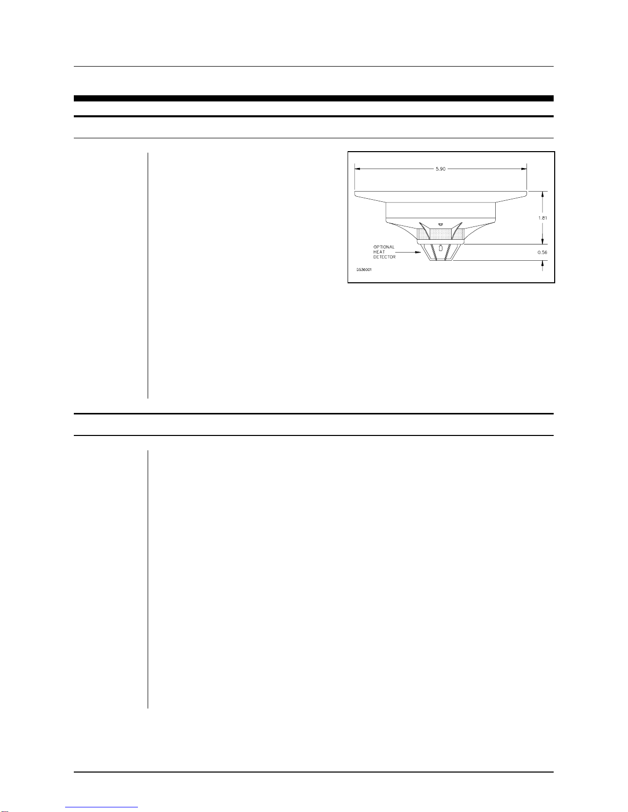
area. For the photoelectric detector only, an optional model is available which incor-
porates a thermistor type heat detector, in addition to the smoke detection capability.
PRINCIPLE OF OPERATION
The burning of any substance typically produces ash which remains at the site, and
volatile products that mix with the air in the vicinity of thefire. The volatile products consist
of a gaseous mixture of minute solid particles and liquid condensates to form what is
generally known as smoke. Note that in some cases, the particles in the smoke are so
small that the smoke is not visible to the human eye. Two commonly used principles of
detecting smoke are the ionization method and the photoelectric method.
The SST Model S250 Ionization Smoke Detectors operate by the principle of sensing a
change in the electrical properties of the air in a chamber that contains a minute quantity
of a radioactive material. Emissions from this material ionize the air in the chamber, thus
rendering it conductive and permitting a small current to flow through theair between two
plates in the chamber. Smoke products entering the chamber impede the flow of this
ionization current. The change in current is sensed by the detector’s circuitry and results
in an alarm signal.
The SST Model S260 Photoelectric Smoke Detectors operate by sensing a change in the
intensity of light shining on a photoelectric cell in the sensing chamber. A light emitting
diode in the chamber is arranged so that its light does not normally shine directly on the
cell. When smoke enters the chamber, the smoke particles “scatter” or reflect the light
onto the photocell. The intensity of light is sensed by the detector’s circuitry and generate
an alarm.
Figure 250-1 Typical Dimensions
DESCRIPTION MODELS S250 AND S260 SMOKE DETECTORS
DESIGN MANUAL December, 2002 250-1

ELECTRICAL SPECIFICATIONS
These detectors are “two-wire smoke detectors” which obtain the operating voltage for
their electronic circuits from the same two wires that are used to transmit an alarm to the
control module. As such, it is important that they be used only with control panels that can
provide the proper operating voltages and have compatible circuits. These detectors
have been designed to work with Safety Systems Technology NOVA-5000 system
modules. The required electrical specifications to insure compatibility are complex. To
ease selection, Compatibility Identifier Numbers have been assigned to each detector,
base and control module.These numbers are listed inTable 250-1. Forreliableoperation,
you must not interconnect components with identifier numbers other than those listed in
the table with these devices.
TABLE 250-1
COMPATIBILITY IDENTIFIER NUMBERS
PRODUCT/DEVICE
DESCRIPTION
COM-
PATIBILITY
IDENTIFIER
NUMBER
MAXIMUM
NUMBER
DETECTORS
PER LOOP
Model S250 Ionization Smoke Detector I51FE1
Model S260 Photoelectric Smoke Detector P55FE1
Model S260 Photoelectric Smoke Detector with 135o
Heat Detector P56FE1
Part No. 280-01 Standard Mounting Base FE51A 55
Part No. 280-02 Remote LED/Test Mounting Base FE52A 55*
Part No. 280-03 Relay Mounting Base FE55A 1
Part No. 285 Air Duct Mounting Base D22FE5 1
Part No. 288-01 Remote Alarm Indicator and Function-
al Test Switch 75*
Model 5010 Dual Channel Smoke/Fire Detection
Module M310 75
*IMPORTANT NOTE: When detectors use the remote LED options, all detectors on a loop
must be equipped with this option.
ELECTRICALSPECIFICATIONS MODELS S250 AND S260 SMOKE DETECTORS
DESIGN MANUAL December, 2002 250-2

ENVIRONMENTAL SPECIFICATIONS
The SST Models S250 and S260 smoke detectors are intended for use in “general
purpose” areas, where explosive atmospheres will not be present. It is difficult to specify
exact limits on the required environment. However, they have been tested by Under-
writers Laboratories for environmental stability. Some of the basic conditions that must
be met for UL compliance are listed below. These areprovided as application guidelines,
indicating typically acceptable environmental conditions.
Temperature
Testing done from 32oto 122oF (0oto 50oC) at 30% to 50% relative humidity. The UL
rated temperature range is 32oto 100oF. Operation outside this range is not recom-
mended.
Humidity
85% at 86oF (30oC), 168 hour test, 20% RH to 90% RH at 73oF (23oC) rapid cycle test.
Air Velocity
1000 feet per minute (5 meters per second) continuous, with gusts up to 2000 FPM (10
m/s) for ionization detectors. 4000 FPM maximum for photoelectric detectors.
Air Pressure
2 inches (51 mm) rapid drop of air pressure starting from 31 inches (787 mm) of mercury.
Altitudes
For altitudes up to 7500 feet above sea level.
Corrosive Atmosphere
a. An atmosphere containing 0.1% hydrogen sulfide by volume in air saturated with water
vapor at room temperature for 10 days.
b. An atmosphere containing 1% carbon dioxide by volume in air saturated with water
vapor at room temperature for 10 days.
In all cases, a Safety Systems Technology (SST) technical representative should be
consulted if the detectors are to be operated under adverse environmental conditions.
SELECTING THE APPROPRIATE DETECTOR
When laying out a fire protection system, the designer must keep in mind the operating
characteristics of the individual detector types as they relate to the area protected. Such
factors as type and quantity of fuel, possible ignition sources, ranges of ambient condi-
ENVIRONMENTALSPECIFICATIONS MODELS S250 AND S260 SMOKE DETECTORS
DESIGN MANUAL December, 2002 250-3

tions, value of the protected property and life safety are critical in the proper design of the
system.
Smoke detectors are best suited for the protection of large open spaces, where the time
required for a fire to generate sufficient heat for detection would be excessively long.
Model S250 Ionization Smoke Detectors are particularly suitable where flaming fires,
exhibiting small products of combustion particles, yet no large particles or appreciable
quantities of heat, are expected. Model S260 Photoelectric Smoke Detectors are
particularly suitable where smoldering fires are expected. The Model S260 with optional
heat detector can provide additional protection when placed directly overhazards where
flaming fires could be expected.
INSTALLATION STANDARDS FOR SMOKE DETECTORS
The location and spacing of smoke detectors should be based on good engineering
judgement, supplemented by the guidelines provided by the authority having jurisdiction.
For most installations, compliance with the applicable sections of NFPA Standard 72,
“National Fire Alarm Code", "Smoke-Sensing Fire Detectors”, is required. The following
information is provided as a guideline, and is believed by SST to be in compliance with
72. However, in case of any conflict, installation should always comply with the require-
ments of the authority having jurisdiction.
LOCATION OF DETECTORS
Per the UL Listing and NFPA installation requirements, open area smoke detectors are
intended for mounting on a ceiling not less than 6 inches from a wall, or on awall not less
than 4 inches nor more than 6 inches from the ceiling. Where high ceilings (16 feet or
greater) are found, smoke travel to the devices may be delayed by air stratification. In
this situation, smoke detectors may need to be installed on sidewalls, or suspended
below ceiling level. Sloped ceilings also require special considerations. Refer to NFPA72
for recommended installation details.
!CAUTION:
Model S250 Ionization Smoke Detectors should notbe installed inthefollowing
locations: areas with excessive exhaust fumes, kitchen areas, near fireplaces
or furnace rooms, or within 3 feet of air supply ducts or air diffusers.
INSTALLATION STANDARDS FOR SMOKE DETECTORS MODELS S250 AND S260 SMOKE DETECTORS
DESIGN MANUAL December, 2002 250-4
SPACING BETWEEN DETECTORS (OPEN AREA LOCATIONS)
The Models S250/S260 series detectors are intended for installation on 30 foot centers
maximum, based on a smooth ceilings up to 15 feet high with minimum air circulation.
This results in a maximum coverage area of 900 square feet. This figure may be used as
a reasonable guide for comparable applications. Where special conditions exist (ceiling
obstructions, high air exchange rates, etc.), reduced square footage spacing must be
used to achieve adequate protection. Computer rooms and other such installations may
require spacing with a maximum of 200 square feet due to high air exchange rates. For
additional information, consult National Fire Protection Association Standard 72.
INSTALLING AND WIRING THE DETECTOR BASES
The Detector Bases are
designed to mount directly on a
standard electrical junction
boxes (3, 3 1/2, or 4 inch round,
square or octagonal). Two sets
of mounting slots on the base
permit installing on the various
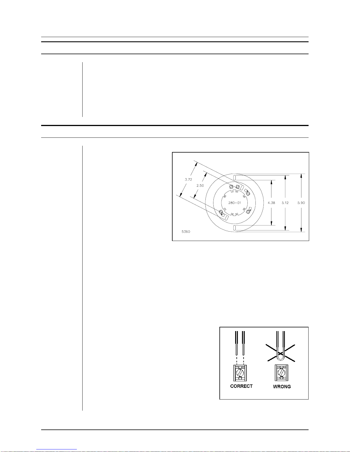
size boxes. Applicable dimen-
sions are shown in Figure 250-
2.
Refer to the typical wiring
diagram, SST drawing
50002,which shows the proper
2-wire smoke detector wiring
methods when using the
various mounting bases.
Make connections to the screw terminals or colored wires on the base per the wiring
diagram. Be sure to connect two individual wires to terminal number 1 as shown in
Figure 250-3. Do not leave these twowires uncut and looped around the screw. This
is to insure that a fault will be signaled if the screw terminal becomes loose and either
wire becomes disconnected.
Dress allwiresaway fromtheconnector terminals
on the base that will mate with the detector, then
mount the base on the junction box.
After alldetectorbasesareinstalled,includingthe
end-of-line resistor, check loop continuity. To
make the continuity check, a preformed spring
jumper wire is supplied with each base, installed
between terminals 6 and 7. With the jumper in
place on each base, measure the resistance be-
tween the two wires at the control panel. (Unplug
the input module if the wires are already ter-
minated on the control panel. You should read
3300 ohms, the end-of-line resistor. After loop Figure 250-3 Wiring Methods
Figure 250-2 Mounting Base Dimensions
SPACING BETWEEN DETECTORS (OPEN AREA LOCATIONS) MODELS S250 AND S260 SMOKE DETECTORS
DESIGN MANUAL December, 2002 250-5

continuity has been verified, remove and discard the temporary jumper wire between
terminals 6 and 7 on the base and install the smoke detector as described below.
Remote Alarm Indicator and Test Switch
These smoke detectors are sometimes installed aboveafalse ceiling, belowa “computer”
floor, or in other less visible or accessable places. In these cases, the detectors can be
installed with SST partnumber 280-02 bases, andwired to aremotealarm indicating LED
and functional test switch. The LED/switch is usually located on a wall in the protected
areaateyelevel. Thewiringdiagramalsoshowstheproperinstallationwiringinthiscase.
Install the bases and test the wiring as indicated in Notes above.
!WARNING: When using the remote LED option, all smoke detectors on the
respective loop must be equipped with that option. Do not use any detectors
without the LED option.
Auxiliary Relay and Duct Mounting Options
When detectors are installed with SST part number 280-03 Relay Mounting Base or 285
Air Duct Mounting Base, detection of smoke will operate the relay in the base, in addition
to transmitting the normal alarm to the control panel. The relay contacts may be used to
perform some local function in the protected area, such as shutting down a critical piece
of equipment, turning on emergency lights, etc. When detectors employ these relay
options, only one detector may be installed on a loop. This is because of the extra power
required to operate the relay. The relay contact symbols (normally open, common,
normally closed) on the wiring diagram are in their normal operating condition — with
power applied and no alarm.
The relay mounting bases are equipped with color coded wire leads to which you will
connect some system wiring. Make all pigtail connections using wire nuts, crimp splices
or other approved connection means. Be sure to insulate any unused leads and the
end-of-line resistor, if used. Refer to the wiring diagrams for color code and interconnec-
tion details. Position wires and connectors in the junction box so as to leave the center
of the box as clear as possible. Then complete the base installation as detailed above.
The duct mounting base does not require a junction box; it installs directly ona heating/air
conditioning duct. Complete instructions are shipped with the base.
INSTALLING AND WIRING THE DETECTOR BASES MODELS S250 AND S260 SMOKE DETECTORS
DESIGN MANUAL December, 2002 250-6

INSTALLATION OF DETECTOR HEAD
!WARNING: TO PREVENT DETECTOR CONTAMINATION AND SUB-
SEQUENT WARRANTY CANCELLATION, SMOKE DETECTORS MUST
REMAIN COVERED UNTIL AREA IS CLEAN AND DUST FREE.
To install the selected head, push the detector head into the base and rotate until the
detector key tabs drop into place. Rotate clockwise about 1/2"travel to engage electrical
connections. The head will automatically lock into place.
These detector bases also include an optional locking feature that prevents removal of
the detector without use of a tool. To eliminate this feature, simply break off the locking
tab on the base, then install the detector. To remove the detector from the base when the
locking feature is used, insert a small-bladed screwdriver into the slot on the base to push
the plastic tab while simultaneously turning the detector head counterclockwise.
DETECTOR ACCEPTANCE TESTS
Before conducting any tests, all persons who would automatically receive an alarm signal
should be notified so that unnecessary response will not take place. All releasing devices
and extinguishing systems should be disconnected or the appropriate control modules
put in the “isolated” mode while the operational test is being performed. At theconclusion
of testing, all parties, including the building occupants, should be notified that testing has
been concluded.
NFPA Standard 72E requires acceptance testing of 100% of the installed smoke detec-
tors. The specified test is to be a Calibrated test method (e.g., magnet or probe test
manufacturer’s calibrated sensitivity instrument) plus test in place functionally. Perform
this test as detailed below.
1.After powering the detector head for approximately 1 minute, check to see that the
alarm indicator LED flashes. Failure to flash indicates a nonfunctioning detector or faulty
wiring. Recheck wiring and replace detector head if necessary.
2.The built-in test feature of the detector can be activated by using a small permanent
magnet. Position the long axis of a test magnet against the side of the detector housing
marked “TEST” for at least 15 seconds. The detector should alarm as indicated by steady
illumination of the alarm indicator. To return each detector to normal operation, reset the
control module.
3.Allow test smoke froma cotton wick or punkor test aerosol toenter the detectorsensing
chamber for a minimum of 10 seconds and observe the red alarm indicator. When
sufficient smoke has entered the chamber, an alarm will be indicated by continuous
illumination of the LED. Reset each detector and control unit after it alarms before
attempting to test additional detectors in the same zone.
DETECTOR SENSITIVITY TESTS
NFPAStandard 72E requires thatthe detector sensitivity be checkedwithin one yearafter
installation, and every alternate year thereafter.Each detector is marked with a sensitivity
INSTALLATION OF DETECTOR HEAD MODELS S250 AND S260 SMOKE DETECTORS
DESIGN MANUAL December, 2002 250-7

rating in percent per foot obscuration. The standard requires that any detector found to
have a sensitivity 0.25 percent/ft obscuration or more outside the marked sensitivity be
replaced.
To conduct sensitivity testing for these smoke detectors, you will need a Model ST001
Sensitivity Test Instrument. The tester is designed for use with a standard digital
voltmeter. It acts as an interface between the detector and the voltmeter, and is arranged
such that the voltmeter reading in volts is equal to the detector sensitivity in percent per
foot obscuration.
The ST001 tester will automatically sense and indicate whether the detector being tested
is a photoelectric or ionization type. It has a built-in calibration and self check test routine
which is run each time the unit is turned on. A battery status LED is provided, and an
automatic power down function shuts the ST001 off shortly after completing each test to
prevent unnecessary battery drain.
Before conducting any tests, all persons who would automatically receive an alarm signal
should be notified so that unnecessary response will not take place.
IMPORTANT: All releasing devices and extinguishing systems should be discon-
nected or the appropriate control modules put in the “isolated” mode while the
operational test is being performed. At the conclusion of testing, all parties, including
the building occupants, should be notified that testing has been concluded. Proceed with
test as follows:
1. Remove the detector head from the baseand note the % perfoot obscurationrange marked
on the detector label undernominal sensitivity.
2. Reinstall the detector head to the base. Allow 1 minute for stabilization. The alarm indicator
should flash approximately once every 4seconds. No flash indicates a nonfunctioning detector
or faulty wiring. Steady illumination indicates an alarm state.
4. Connect the sensitivity tester and voltmeter as described below. Be sure to observe the polarity
(+) and (-) markings for all connections.
a. Connect test leads between the Voltmeter connections on the ST001 tester and
the input of a digital voltmeter. Set the digital voltmeter to read 0 to 5 volts DC.
b. Connect test leads between the Detector connections on the ST001 tester and
the two test jacks on the front of the detector. The (+) lead must be plugged into the
round hole on the detector. The (-) lead must be plugged into the key shaped hole
on the detector.
5. Turn on the tester by pressing the blackcircle labeled POWER. Confirm that the battery
indicator illuminates steady on. (Replace battery in tester if LED flickers or does not light.)
DETECTOR SENSITIVITYTESTS MODELS S250 AND S260 SMOKE DETECTORS
DESIGN MANUAL December, 2002 250-8

6. The PHOTO or ION LED should illuminate and a voltage corresponding to the detector
sensitivity should appearon the meter. The reading may take upto20 seconds tostabilize. The
sensitivity in percent per foot obscuration is directly read on the meter.
Example:
Meter displays 3.14; then sensitivity = 3.14 %/ft
Meter displays 0.89; then sensitivity = 0.89 %/ft
7. Sensitivity readings that are not within 0.25 %/ft of the marked sensitivity of the detector are
unacceptable. First, try cleaning the detector as outlined under maintenance and repeat the tests.
If readings are still out of the allowable range, replace the detector.
8. After all the tests are complete, be certain that the complete system is returned to normal.
MAINTENANCE
Maintenance Schedule
1. The recommended requirement for detector maintenance consists of an annual cleaning of
dust from the detector head by using the suction of vacuum cleaner. Cleaning programs should
be geared to the individual environment in conformance with NFPAStandard 72.
!CAUTION: DO NOT ATTEMPT DISASSEMBLY OF THE FACTORYSEALED
SMOKE DETECTOR. THIS ASSEMBLY IS SEALED FOR YOUR PROTEC-
TION AND IS NOT INTENDED TO BE OPENED FOR SERVICING. OPEN-
ING OF THE DETECTOR WILL VOID THE WARRANTY.
2. Perform the SensitivityMetering Test as described above within one year after installation.
Confirm that the sensitivity readings are within specified limits on detector label. Thereafter,
perform sensitivity tests every 2 years.
3. In alternate years (when sensitivity test is not required), perform a functional test on all smoke
detectors, using the test magnet or test smoke to initiate an alarm.
Repair of failed detectors
The ionization detectors contain a small amount of radioactive material. Total radioac-
tivity: 7 microcuries (maximum) Americium 241 shielded by stainless steel housing. No
field repair should be attempted. Due to the low cost of these smoke detectors, it is not
feasable to repair failed units. Replace failed detectors with new ones.
MAINTENANCE MODELS S250 AND S260 SMOKE DETECTORS
DESIGN MANUAL December, 2002 250-9

DESIGN MANUAL December, 2002 250-10
This manual suits for next models
1
Table of contents


