SSV Embedded Systems MGW/920 User manual

M
GW/
920
Smart Metering Gateway
First Steps
SSV Embedded Systems
Heisterbergallee 72
D-30453 Hannover
Phone: +49 (0)511/40 000-0
Fax: +49 (0)511/40 000-40
E-mail: sales@ist1.de Manual Revision: 1.1
Date: 2008-05-08
For further information regarding our products please visit us at www.ssv-embedded.de

MGW/920 Smart Metering Gateway- First Steps
2
Manual Revision 1.1
CONTENT
1INTRODUCTION...............................................................................................................3
1.1 Safety Guidelines...................................................................................................................3
1.2 Conventions...........................................................................................................................3
1.3 Application Environment.......................................................................................................4
1.4 Features and Technical Data..................................................................................................5
2OVERVIEW .......................................................................................................................6
3GETTING STARTED.........................................................................................................7
3.1 Ethernet Link between MGW/920 and PC.................................................................................7
3.2 Connecting Power Supply and Power-up the MGW/920.............................................................8
3.3 Checking IP Address of PC...................................................................................................9
3.4 Checking Ethernet-based TCP/IP Communication .............................................................10
3.5 Changing Ex Factory IP Address (IPbyNet) .......................................................................11
4MECHANICAL DIMENSIONS .........................................................................................13
5PINOUTS ........................................................................................................................14
5.1 Ethernet Interface (RJ45).....................................................................................................14
5.2 M-Bus Master Interface (RJ12)...........................................................................................14
6HELPFUL LITERATURE.................................................................................................15
CONTACT..............................................................................................................................15
DOCUMENT HISTORY .........................................................................................................15

MGW/920 Smart Metering Gateway- First Steps
Manual Revision 1.1
3
1 INTRODUCTION
The default configuration of an MGW/920 Smart Metering Gateway contains one
10/100 Mbps Ethernet LAN interface and one M-Bus master interface for up to ten external
M-Bus meters.
For using the MGW/920 you need an Ethernet link to your PC or to an Internet router. This
link needs a standard Ethernet patch or cross-over cable.
1.1 Safety Guidelines
Please read the following safety guidelines carefully! In case of property or personal
damage by not paying attention to this document and/or by incorrect handling, we do
not assume liability. In such cases any warranty claim expires.
ATTENTION: Observe precautions for handling – electrostatic sensitive device!
•Discharge yourself before you work with the device, e.g. by touching a heater of
metal, to avoid damages.
•Stay grounded while working with the device to avoid damage through electrostatic
discharge.
1.2 Conventions
Convention Usage
bold
Important terms
italic
Filenames, user inputs
monospace Pathnames, program code, command lines
Table 1: Conventions used in this Document

MGW/920 Smart Metering Gateway- First Steps
4
Manual Revision 1.1
1.3 Application Environment
Figure 1 shows the typical application environment for the MGW/920 Smart Metering
Gateway. One side is connected over the M-Bus (metering Bus) to gas, electricity, water or
other types of consumption meters. The other side offers an IP-based Internet link via wired
xDSL (Ethernet) or wireless GPRS (GSM/GPRS modem).
The application environment allows the transfer of energy consumption data over the Inter-
net as an IP-based network to IT-hosted monitoring, billing or management applications in
real time.
Fig. 1: Application Environment for the MGW/920

MGW/920 Smart Metering Gateway- First Steps
Manual Revision 1.1
5
1.4 Features and Technical Data
•MGW/920 with DIL/NetPC DNP/9200 @ 180 MHz
•1x Real Time Clock (RTC) with battery backup
•1x M-Bus master interface (RJ12)
•1x 10/100 Mbps Ethernet LAN interface (RJ45)
•6x status LED
•Modem socket for GSM/GPRS modem expansion
The MGW/920 M-Bus master interface supports up to ten external M-Bus meters and a max.
distance of 10 km. The M-Bus communication speed can range from 300 to 19.200 bps.

MGW/920 Smart Metering Gateway- First Steps
6
Manual Revision 1.1
2 OVERVIEW
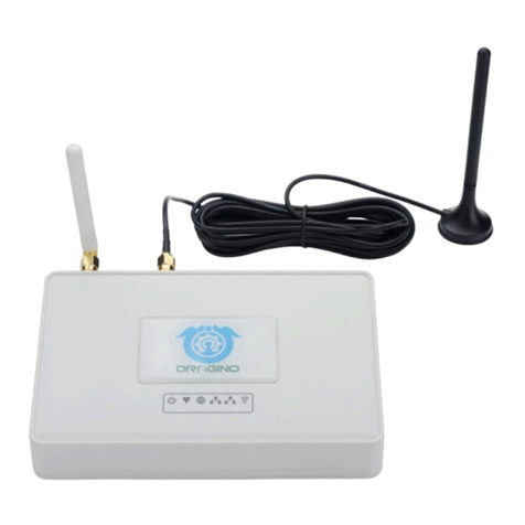
Fig. 2: Overview MGW/920

MGW/920 Smart Metering Gateway- First Steps
Manual Revision 1.1
7
3 GETTING STARTED
3.1 Ethernet Link between MGW/920 and PC
Setup the Ethernet link between the Ethernet connector of the MGW/920 and your PC.
Use an Ethernet cross-over cable or a router-based infrastructure for the Ethernet connec-
tion.
Fig. 3: Ethernet link between MGW/920 and PC
Please note: The MGW/920 comes with the default IP address 192.168.0.126.
Please make sure that your PC can work with the IP address range 192.168.0.x.
Fig. 4: Router-based Ethernet link between MGW/920 and PC

MGW/920 Smart Metering Gateway- First Steps
8
Manual Revision 1.1
3.2 Connecting Power Supply and Power-up the MGW/920
Connect the 12 VDC power supply with the 5.5 mm x 2.5 mm barrel plug to the
MGW/920.
Fig. 5: Power supply for the MGW/920
CAUTION: Providing the MGW/920 with a voltage higher than the regular 12 VDC
±10 % could resolve in damaged board components!
Please pay attention to the polarity of the power connector: the + pole is in the center!
Fig. 6: Polarity of the power connector

MGW/920 Smart Metering Gateway- First Steps
Manual Revision 1.1
9
3.3 Checking IP Address of PC
Make sure that your PC is using the right IP address for the Ethernet-based TCP/IP com-
munication with the MGW/920. Use 192.168.0.1 or 192.168.0.254 for your PC and
192.168.0.126 for the MGW/920.
Fig. 7: Windows-PC IP address check with ipconfig
Talk to your network administrator if you have problems with the IP address understand-
ing.

MGW/920 Smart Metering Gateway- First Steps
10
Manual Revision 1.1
3.4 Checking Ethernet-based TCP/IP Communication
Check the Ethernet-based TCP/IP communication between the MGW/920 and the PC
with a simple ping command.
Fig. 8: Windows-PC TCP/IP communication check with ping
First check the cable connections and then the IP addresses if your ping does not work.
Then check the TCP/IP setup of your PC.

MGW/920 Smart Metering Gateway- First Steps
Manual Revision 1.1
11
3.5 Changing Ex Factory IP Address (IPbyNet)
The ex factory value for the default IP address is 192.168.0.126. The network mask
for this address is 255.255.255.0. You can change the IP address and the network
mask over an Ethernet link with the MGW/920 IPbyNET feature.
Fig. 9: Environment for IP address change with IPbyNet
IPbyNET is a MGW/920 firmware component, which checks directly after each boot
process the presence of ICMP echo request packets with the MAC address of the
MGW/920 Ethernet interface. If an ICMP packet is available, the IPbyNET firmware ex-
tracts the destination IP address from the ICMP echo request packet and sets the
MGW/920 Ethernet interface with this IP address.
Fig. 10: Changing the IP address with IPbyNet
Please see the label with the MAC address on the front of your MGW/920 to find the
MAC address for your MGW/920. Then run a Windows command prompt and enter the
following two command lines:
arp –s 192.168.0.10 02-80-AD-20-D3-7F
ping –t –w 300 192.168.0.10

MGW/920 Smart Metering Gateway- First Steps
12
Manual Revision 1.1
The first command line creates an ARP table entry for the IP address 192.168.0.10
and the MAC address 02-80-AD-20-D3-7F. The second command line sends an
ICMP echo request to the device with the MAC address 02-80-AD-20-D3-7F. This
request contains the new IP address 192.168.0.10.
Change the IP address and the MAC address of the two command lines. Use the IP ad-
dress of your needs and the given MAC address from your MGW/920.
Then reboot the MGW/920. After a few seconds the MGW/920 responds to the ping with
the new IP address.

MGW/920 Smart Metering Gateway- First Steps
Manual Revision 1.1
13
4 MECHANICAL DIMENSIONS
All length dimensions have a tolerance of 0.5 mm. The keyhole drillings are suitable for
M4 screws.
Fig. 11: Mechanical dimensions of the MGW/920

MGW/920 Smart Metering Gateway- First Steps
14
Manual Revision 1.1
5 PINOUTS
5.1 Ethernet Interface (RJ45)
Pin
Name Function
1
TX+ 10/100 Mbps LAN, TX+ Pin
2
TX- 10/100 Mbps LAN, TX- Pin
3
RX+ 10/100 Mbps LAN, RX+ Pin
4
--- Not Connected
5
--- Not Connected
6
RX- 10/100 Mbps LAN, RX- Pin
7
--- Not Connected
8
--- Not Connected
Table 2: Pinout Ethernet interface
5.2 M-Bus Master Interface (RJ12)
Pin
Name Function
1
--- Not Connected
2
--- Not Connected
3
MBUS2 M-Bus Signal 2 (+)
4
MBUS1 M-Bus Signal 1 (-)
5
--- Not Connected
6
--- Not Connected
Table 3: Pinout M-Bus master interface

MGW/920 Smart Metering Gateway- First Steps
Manual Revision 1.1
15
6 HELPFUL LITERATURE
•DIL/NetPC DNP/9200 hardware reference
•MB/920-E2M Base Board hardware reference
CONTACT
SSV Software Systems
Heisterbergallee 72
D-30453 Hannover / Germany
Phone: +49 (0)511/40 000-0
Fax: +49 (0)511/40 000-40
Internet: www.ssv-embedded.de
Support: www.ssv-comm.de/forum
For actual information about the MGW/920 visit us at
www.ssv-comm.de.
DOCUMENT HISTORY
Revision Date Remarks Name
1.0 2008-04-21 first version WBU
1.1 2008-05-08 product name changed WBU
The content of this document can change any time without an
nouncement. There is taken over no guarantee
for the accuracy of the statements. The user assumes the en
tire risk as to the accuracy and the use of this
document. Information in this docu
ment is provided ‘as is’ without warranty of any kind. Some names within
this document can be trademarks of their respective holders.
© 2008 SSV EMBEDDED SYSTEMS. All rights reserved.
Table of contents
