2
ASV
Stübbe
GmbH
&
Co.
KG
•
Hollwieser
Straße
5
•
D-3
2602
Vlotho
• Fon +49(0) 57 33 - 7 99-0 • Fax +49 (0) 57 33 - 7 99-50 00 • www.asv-stuebbe.de • cont[email protected] 1.2 Installation und Inbetriebnahme
Ein sicherer Betrieb des Niveauschalters setzt
voraus, dass der Monteur für die Installation
und Inbetriebnahme folgende Qualifikationen
besitzt bzw. sicherheitsbewusste
Arbeitsabläufe berücksichtigt!
1.2.1 Der Monteur muss eine fachbezogene Quali-
fikation im Kunststoffrohrleitungsbau besitzen.
1.2.2 Der Monteur hat sich vor Beginn aller Arbeiten
bei dem Betreiber der Anlage über die
Gefahren, die von Anlage/Medium ausgehen
können, zu informieren und hat diesbezügliche
Schutz- und Sicherheitsmaßnahmen zu
befolgen.
1.2.3 Der Monteur hat sicherzustellen, dass das
Einschalten/Anfahren der Anlage bei der
Installation, Wartung oder Instandsetzung
nicht möglich ist. Strom- und Druckluft-
versorgung sind sicher vom Netz zu trennen
und gegen unbefugtes Einschalten zu sichern.
1.2.4 Der Monteur hat sicherzustellen, dass die
Rohrleitungskomponenten unter Beachtung der
Sicherheitsvorschriften drucklos sind, entleert
und dekontaminiert wurden. Nachlaufende
Mediumreste sind aufzufangen.
1.3 Bestimmungsgemäße Verwendung
Zur Überwachung von Flüssigkeitsständen in
drucklosen Behältern oder offenen Gruben.
Als Signalgeber bei Unterschreitung sowie bei
Überschreitung einer festgelegten
Füllstandshöhe.
Infolge der Luftabsorptionsfähigkeit der
meisten Flüssigkeiten sind die Tauchrohre in
gewissen Zeitabständen zu belüften, um
Schaltpunktverschiebungen zu vermeiden!
1.3.1 Arbeitsweise
Der Niveauschalter NIS enthält 1 bis 4
Membrandruckschalter und die gleiche Anzahl
mit ihnen verbundener Tauchrohre.
Steigt das Flüssigkeitsniveau, wird die in den
Tauchrohren befindliche Luft komprimiert.
Bei einer Druckerhöhung von max. 10 mbar
(Niveauunterschied von 100 mm H2O), wird
über die Membrane ein Sprungschalter
betätigt.
Sinkt das Niveau um max. 50 mm, entspannt
sich die im Tauchrohr befindliche Luft und es
erfolgt die Rückschaltung.
1.3.2 Beständigkeitsprüfung
Alle mediumberührten Bauteile des
Niveauschalters müssen nach der ASV
Beständigkeitsliste für das verwendete Medium
»beständig« sein.
ASV-Beständigkeitsliste beachten!
1.3.3 Temperaturprüfung
PVC-U: bis max. 60°C
PP: bis max. 80°C
1.3.4 Typenschildangabe
Die Typenschildangaben müssen mit den
Bestell-/Auslegungsdaten übereinstimmen.
2. Installationshinweise
Beachten Sie die Sicherheitshinweise!
Des Weiteren sind zu beachten:
DIN, DIN/ISO, DVS, nationale und
internationale Normen, die Verkleberichtlinien
(PVC-U, PVC-C) bzw. die Schweißrichtlinien
(PP, PVDF) für Kunststoffarmaturen.
1.2 Installation and commisioning
Safe operation of the level switch requires that
the fitter carrying out installation and start-up
has the following qualifications and takes into
account safety relevant operating sequences.
1.2.1 The fitter must have expert qualifications in
plastic pipework construction.
1.2.2 Prior to starting any work, the fitter must
obtain information from the user/owner of the
system regarding any potential hazards
emanating from the system/medium and must
observe all pertinent protection and safety
measures accordingly.
1.2.3 The fitter must make sure that switching on/
starting up of the system is impossible during
installation, maintenance or repairs. Reliably
disconnect the power supply as well as the
compressed air supply from the networks and
prevent unauthorised activation.
1.2.4 The fitter must ensure that the pipework
components are depressurised, emptied and
decontaminated while taking the safety
instructions into account. Collect any residual
fluid accordingly.
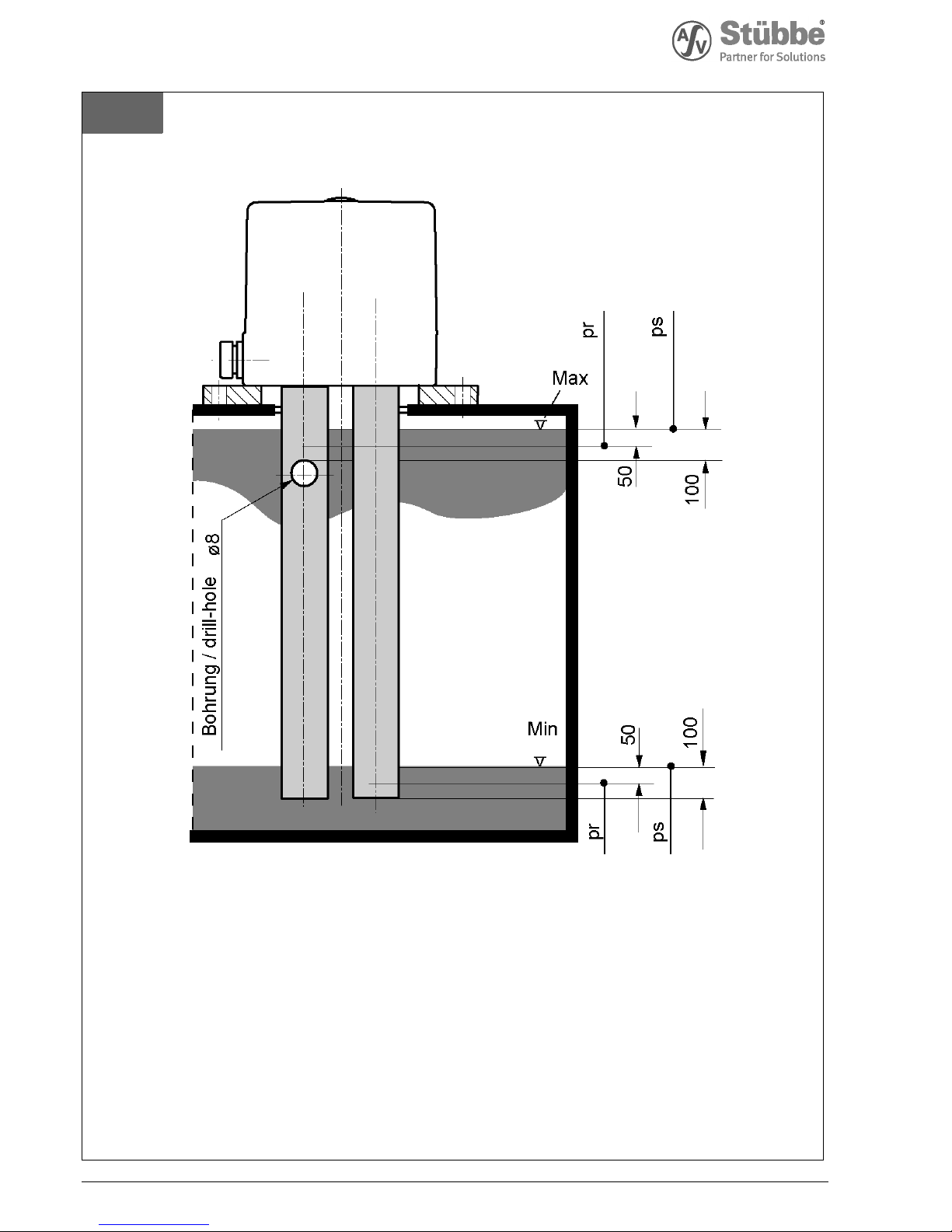
1.3 Intended use
For monitoring fluid levels in pressureless
containers or open pits.
For signalling if the level exceeds or falls below
a set filling level
Due to the air absorption properties of most
fluids, aerate the immersion tubes at regular
intervals to prevent any displacement of the
switching points.
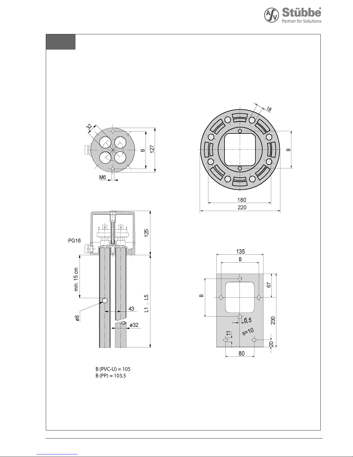
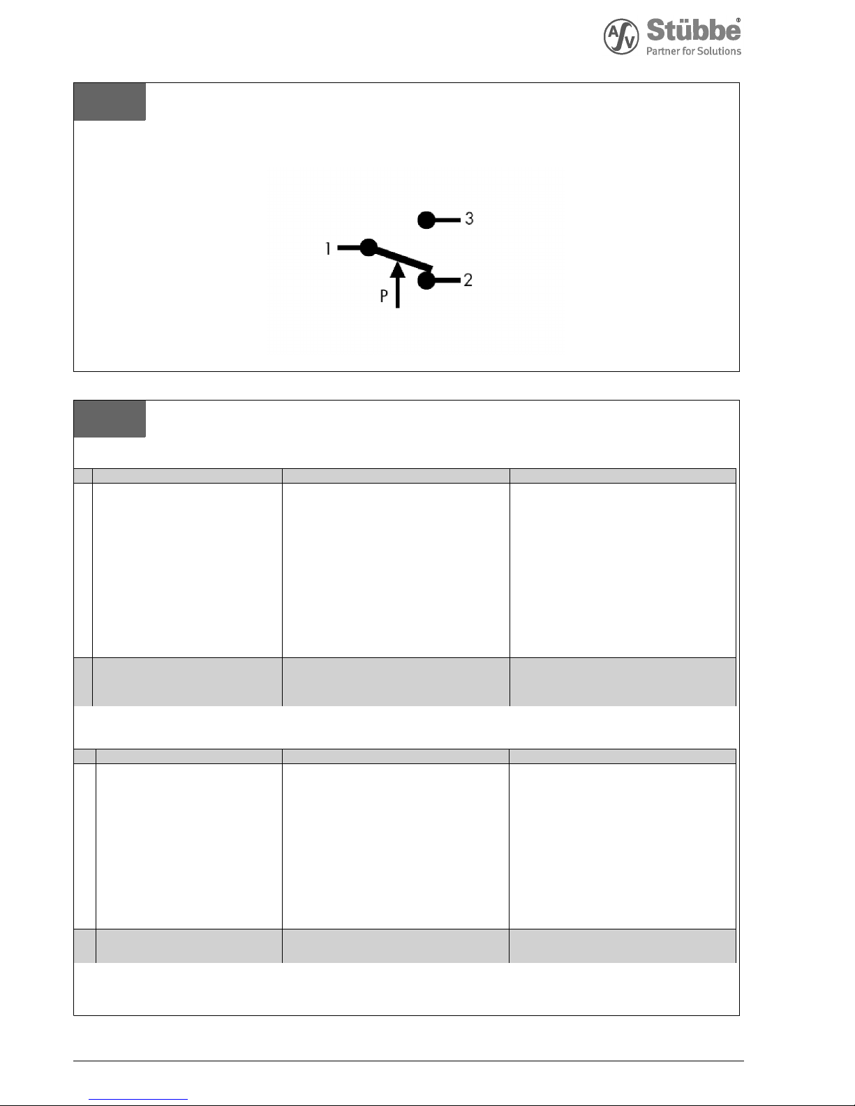
1.3.1 Operating principle
The level switch NIS contains 1 to 4 diaphragm
pressure switches and the same number of
immersion tubes connected to them.
When the fluid level rises, the air in the
immersion tubes is compressed.
At a pressure increase of max. 10 mbar (level
difference of 100 mm H2O), the diaphragm
activates a snap-action switch.
If the level drops by a maximum of 50 mm, the
air pressure in the immersion tube drops and a
reset occurs.
1.3.2 Resistance test
All components of the level switch getting into
contact with the medium must be »resistant«
according to the ASV resistance guide.
1.3.3 Temperature test
PVC-U: up to max. 60°C
PP: up to max. 80°C
1.3.4 Identification plate
The information on the identification plate must
coincide with the order/design data.
2. Installation notes
Adhere to the safety instructions.
In addition observe:
DIN, DIN/ISO, DVS*, national and international
standards, the regulations for solvent welding
(PVC-U, PVC-C) or fusion welding (PP, PVDF) of
thermoplastic valves.
*DVS = German Welding Society