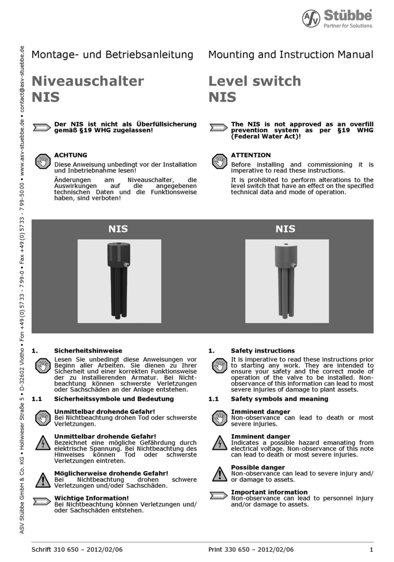
Stübbe NIS Series Installation instructions

Level switch
Original operating manual Series
NIS
Version BA-2022.10.26 EN
Print-No. 302 499
TR MA DE Rev001
STÜBBE GmbH & Co. KG
Hollwieser Straße 5
32602 Vlotho
Germany
Phone: +49 (0) 5733-799-0
Fax: +49 (0) 5733-799-5000
E-mail: co[email protected]
Internet: www.stuebbe.com
Subject to technical modifications.
Read carefully before use.
Save for future use.

Table of contents
Table of contents
1 About this document ............................... 3
1.1 Target groups ................................. 3
1.2 Other applicable documents ................ 3
1.3 Warnings and symbols ....................... 3
2 General safety instructions ....................... 4
2.1 Intended use .................................. 4
2.2 General safety instructions .................. 4
2.2.1 Obligations of the operating company ...... 4
2.2.2 Obligations of personnel ..................... 4
2.3 Hazardous media ............................ 4
3 Layout and Function ............................... 5
3.1 Type plate ..................................... 5
3.2 Description .................................... 5
3.3 Assembly ..................................... 5
4 Transport, Storage and Disposal ................. 5
4.1 Unpacking and inspection on delivery .. .. .. 5
4.2 Transportation ................................ 5
4.3 Storage ....................................... 5
4.4 Disposal ....................................... 6
5 Installation and connection ....................... 6
5.1 Preparations for installation ................. 6
5.1.1 Check operating conditions ................. 6
5.1.2 Preparation of the vessel .................... 6
5.2 Preparation of the device .................... 6
5.2.1 Connecting the immersion tubes ........... 6
5.2.2 Setting the switching points ................. 7
5.2.3 Application examples for the variants NIS 1
to NIS 4 ....................................... 7
5.3 Install device .................................. 8
5.4 Electrical connection of device .............. 8
6 Commissioning ..................................... 8
7 Maintenance ......................................... 9
7.1 Servicing ...................................... 9
7.2 Maintenance .................................. 9
7.2.1 Removing the device ........................ 9
7.2.2 Replacement parts and return .............. 9
8 Troubleshooting .................................... 10
9 Appendix ............................................. 10
9.1 Technical data, operating limits and
weights ........................................ 10
9.2 Connection diagram ......................... 10
9.3 Dimensions ................................... 11
9.4 Accessories ................................... 11
9.4.1 Mounting flange .............................. 11
9.4.2 mounting plate ................................ 11
List of figures
Fig. 1 Type plate .................................... 5
Fig. 2 Assembly (example: NIS 4) ................. 5
Fig. 3 Connecting the immersion tubes ............ 6
Fig. 4 Setting the switching points ................. 7
Fig. 5 Switching point for NIS 1 .................... 7
Fig. 6 Switching points for NIS 2 ................... 7
Fig. 7 Switching points for NIS 3 ................... 8
Fig. 8 Switching points for NIS 4 ................... 8
Fig. 9 Electrical connection of device .............. 8
Fig. 10 Connection diagram ......................... 10
Fig. 11 Dimensions ................................... 11
Fig. 12 Mounting flange .............................. 11
Fig. 13 mounting plate ................................ 11
List of tables
Tab. 1 Other application documents, purpose and
where found .................................. 3
Tab. 2 Warnings and symbols ....................... 3
Tab. 3 Servicing activities ........................... 9
Tab. 4 Troubleshooting .............................. 10
2 NIS BA-2022.10.26 EN 302 499

About this document
1 About this document
This manual:
• is part of the equipment
• applies to all series referred to
• describes safe and proper operation during all operating
phases
1.1 Target groups
Operating company
• Responsibilities:
– Always keep this manual accessible where the device
is used on the system.
– Ensure that employees read and observe this docu-
ment, particularly the safety instructions and warnings,
and the documents which also apply.
– Observe any additional country-specific rules and reg-
ulations that relate to the system.
Qualified personnel, fitter
• Mechanics qualification:
– Qualified employees with additional training for fitting
the respective pipework
• Electrical qualification:
– Qualified electrician
• Transport qualification:
– Qualified transport specialist
• Responsibility:
– Read, observe and follow this manual and the other
applicable documents, especially all safety instructions
and warnings.
1.2 Other applicable documents
To download:
Resistance Guide
Chemical resistance of the materials
used
www.stuebbe.com/pdf/300051.pdf
To download:
NIS data sheet
Technical specifications, conditions of
operation
www.stuebbe.com/pdf/302505.pdf
To download:
CE declaration of conformity
Conformity with standards
www.stuebbe.com/pdf/300773.pdf
Tab. 1 Other application documents, purpose
and where found
1.3 Warnings and symbols
Symbol Meaning
• Immediate acute risk
• Death, serious bodily harm
• Potentially acute risk
• Death, serious bodily harm
• Potentially hazardous situation
• Minor injury
• Potentially hazardous situation
• Material damage
Safety warning sign
Take note of all information
highlighted by the safety warning
sign and follow the instructions to
avoid injury or death.
Instruction
1., 2., ... Multiple-step instructions
Precondition
→Cross reference
Information, notes
Tab. 2 Warnings and symbols
302 499 BA-2022.10.26 EN NIS 3

General safety instructions
2 General safety instructions
The manufacturer accepts no liability for damages caused
by disregarding any of the documentation.
2.1 Intended use
The device is used to monitor liquid levels in unpressurized
vesselsandopenpits. Thedeviceisalsousedasasignal
transmitter when the level rises above or falls below a specified
level.
• Only use the device with suitable media
(→ resistance lists).
• Adhere to the operating limits (→ Data sheet).
• Not for use as an overfill protection device for WHG §19
purposes. The devise is not a safety system.
Avoidance of obvious misuse (examples)
• Do not use the device in a position inverted from the cor-
rect installation orientation (correct installation orientation:
perpendicular, from top to bottom).
• Vent the immersion tubes regularly. If the immersion tubes
are not vented, shifts in the switching points may occur due
to the propensity of the pumped media to absorb air.
• Do not adjust the pressure adjustment screws on the
diaphragm pressure switches. The pressure setting
screws are correctly preset by the manufacturer. Adjusting
the pressure setting screws may cause in the switching
points to be shifted.
2.2 General safety instructions
Observe the following regulations before carrying out any
work.
2.2.1 Obligations of the operating company
Safety-conscious operation
• Only operate the device if it is in perfect technical condition
and only use it as intended, staying aware of safety and
risks, and in adherence to the instructions in this manual.
• Ensure that the following safety aspects are observed and
monitored:
– Intended use
– Statutory or other safety and accident-prevention reg-
ulations
– Safety regulations governing the handling of haz-
ardous substances
– Applicable standards and guidelines in the country
where the pump is operated
• Make personal protective equipment available.
Qualified personnel
• Make sure all personnel tasked with work on the device
have read and understood this manual and all other appli-
cable documents, especially the safety, maintenance and
repair information, before they start any work.
• Organize responsibilities, areas of competence and the
supervision of personnel.
• The following work should be carried out by specialist tech-
nicians only:
– Installation, repair and maintenance work
– Work on the electrical system
• Make sure that trainee personnel only work on the device
under supervision of specialist technicians.
2.2.2 Obligations of personnel
Only complete work on the device if the following requirements
are met:
• System is empty
• System has been flushed
• System is depressurized
• System has cooled down
• System is secured against being switched back on again
• Do not make any modifications to the device
2.3 Hazardous media
• When handling hazardous media, observe the safety reg-
ulations for the handling of hazardous substances.
• Use personal protective equipment when carrying out any
work on the device.
• Collect leaking pumped liquid and residues in a safe man-
ner and dispose of in accordance with environmental reg-
ulations.
4 NIS BA-2022.10.26 EN 302 499

Transport, Storage and Disposal
3 Layout and Function
3.1 Type plate
NIS 4
Schaltleistung
Id.No.
130748
1304-05371
1
2
3
4
-100 mA/24 VAC | -30mA/24 VDC
Material PVC-U
Fig. 1 Type plate
1Devicetype
2 Switching capacity
3 Material
4 ID number
3.2 Description
Thedevicemonitorsliquidlevelsinunpressurizedvesselsand
open pits. The sensor does not require an additional power
supply and actuates a potential-free switching contact when
the level rises above or falls below the specified level.
• Depending on the variant, the device carries 1 to 4
diaphragm pressure switches/immersion tubes
• The switching behavior depends on the air pressure/fluid
level in the immersion tube:
– The switch is set to „On“ when the air pressure rises
by max. 10 mbar / level difference rises by more than
100 mm H2O
– The switch is set to „Off“ when the air pressure falls
by max. 5 mbar / level difference falls by more than
50 mm H2O
3.3 Assembly
1
2
3
Fig. 2 Assembly (example: NIS 4)
1 Housing
2 Diaphragm pressure switch (concealed)
3 Immersion tube
4 Transport, Storage and
Disposal
4.1 Unpacking and inspection on delivery
1. Unpack the device when received and inspect it for trans-
port damage and completeness.
2. Check that the information on the type plate agrees with
the order/design data.
3. Report any transport damage to the manufacturer immedi-
ately.
4. If fitted immediately: Dispose of packaging material
according to local regulations.
– If fitted at a later point: leave device in its original pack-
aging.
4.2 Transportation
Device should preferably be transported in the original
packaging.
4.3 Storage
NOTE
Material damage due to inappropriate storage!
Store the device properly.
1. Make sure the storage room meets the following condi-
tions:
–Dry
– Frost-free
– Vibration-free
– Not in direct sunlight
– Storage temperature +10 °C to +60 °C
2. Device should preferably be stored in the original packag-
ing.
302 499 BA-2022.10.26 EN NIS 5

Installation and connection
4.4 Disposal
Plastic parts can be contaminated by poisonous or radioac-
tive media to such an extent that cleaning will not be suffi-
cient.
WARNING
Risk of poisoning and environmental damage from
medium!
Use personal protective equipment when carrying out any
work on the device.
Prior to the disposal of the device: Neutralize residues of
medium in the device.
1. Remove electronic parts and dispose of in accordance with
local regulations.
2. Dispose of plastic parts in accordance with local regula-
tions.
5 Installation and connection
5.1 Preparations for installation
5.1.1 Check operating conditions
1. Ensure the required operating conditions are met:
– Resistance of body and seal material to the medium
(→ resistance lists).
– Media temperature (→ Data sheet).
– Operating pressure (→ Data sheet).
2. Consult with the manufacturer regarding any other use of
the device.
5.1.2 Preparation of the vessel
The device can be installed in closed, pressureless and
open containers.
The device can be installed by means of a threaded
insert on the lower part of the housing or by means of
a suitable mounting device, e.g. mounting flange or
mounting plate (→ 9.4 Accessories, Page 11).
1. Check that the vessel provides sufficient immersion depth.
2. Align the vessel correctly, ensuring the following points are
satisfied:
– Vertical mounting position of the device
– Sufficient space for installation, electrical connection
and maintenance (→ 9.3 Dimensions, Page 11).
5.2 Preparation of the device
5.2.1 Connecting the immersion tubes
Connection types:
– PVC socket end for solvent welding
– PP fusion socket end
43 mm
1
3
2
Fig. 3 Connecting the immersion tubes
1 diaphragm pressure switch
2 Bottom section of casing
3 Immersion tube
The device installation is complete.
Depending on the type of connection, glue or weld the
immersion tube (3) to the lower part of the housing (2).
Only the manufacturer may perform welding of the variants
NIS 2 to NIS 4 in PP, because a special tool is required for
welding the tubes at the pitch of 43 mm.
6 NIS BA-2022.10.26 EN 302 499

Installation and connection
5.2.2 Setting the switching points
Fig. 4 Setting the switching points
Max Max. filling level
Min Min. filling level
pr Switching point for discharging
ps Switching point for filling
The device installation is complete.
The immersion tubes are connected.
Tool: Power drill, 8 mm drill bit
1. Check the fill levels of the vessel and select the switching
point accordingly.
2. Cut the immersion tubes to length as required.
3. Drillan8mmholeintotheimmersiontube100mmbelow
the selected switching point. Ensure the necessary spac-
ingof≥150mmfromthedrilledholetothelowerpartof
the housing.
5.2.3 Application examples for the variants
NIS 1 to NIS 4
NIS 1
Max
Fig. 5 Switching point for NIS 1
L1 switches the pump off when the maximum fill level (Max) is
reached.
NIS 2
Max
Min
Fig. 6 Switching points for NIS 2
L1 switchesthesubmersiblepumponwhenthemaximumfill
level is reached. L2 switches the submersible pump off when
the minimum fill level is reached.
On the vessel, the shut-off valve is opened at (Max) fill level
and closed at (Min) fill level.
302 499 BA-2022.10.26 EN NIS 7

Commissioning
NIS 3
1
2
3
Fig. 7 Switching points for NIS 3
L1 outputs a warning signal when the fill level 1is reached.
L2 switchesthepumponwhenthefilllevel2is reached.
L3 switches the pump off when the fill level 3is reached.
NIS 4
1
2
3
4
Fig. 8 Switching points for NIS 4
L1 outputs a warning signal when the fill level 1is reached.
L2 switches both pumps on when the fill level 2is reached.
L3 switchesonepumponwhenthefilllevel3is reached.
L4 switches both pumps off when the fill level 4is reached.
5.3 Install device
WARNING
Risk of injury and poisoning due to medium spraying out!
Use personal protective equipment when carrying out any
work on the fitting.
The device installation is complete.
The device is prepared.
Screw in the threaded inserts so that the device when
mounted in the container is perpendicular to the surface
of the media.
5.4 Electrical connection of device
2
3
4
1
5
Fig. 9 Electrical connection of device
1 Plug 4 diaphragm pressure
switch
2Top part of the housing 5Cable gland
3Screw
The unit must be installed properly.
Power supply must be switched off and secured against
being switched back on again.
1. Removetheplug(1).
2. Undo screw (3).
3. Remove the top part of the housing (2).
4. Guide connection cable through the cable gland (5) and
connect it to the diaphragm pressure switch (4):
– Electrical data (→ Data sheet).
– Connection diagram (→ 9.2 Connection diagram,
Page 10).
5. Tighten the cable gland securely.
6. Tighten the top part of the housing.
6 Commissioning
The device is installed and connected.
Switch on power supply.
Depending on the actual filling level, the device will now
trigger a switching operation.
8 NIS BA-2022.10.26 EN 302 499

Maintenance
7 Maintenance
WARNING
Risk of injury and poisoning due to hazardous media and
improper operating procedure!
Use personal protective equipment when carrying out any
work on the device.
Disconnect the power supply and secure it against being
switched back on again.
Block the infeed of media to the vessel / the device.
Safely collect the media and dispose of it in accordance
with environmental regulations.
7.1 Servicing
Interval Action
The interval
is defined by
the operating
company
Check the switching function. If the
switching points have shifted
– Take the device out of the vessel
and vent the immersion tubes.
– Install device.
As necessary Clean device with a damp cloth.
Six-monthly Perform a visual and functional check:
– Normal operating conditions
unchanged
– No leaks
Tab. 3 Servicing activities
Perform maintenance tasks according to the table.
7.2 Maintenance
7.2.1 Removing the device
System is empty.
System has been flushed.
System is depressurized.
System has cooled down.
System must be secured against being switched back on
again.
1. Unplug connection cable.
2. Take the device out of the vessel.
3. Decontaminate device if required.
7.2.2 Replacement parts and return
1. Have the following information ready to hand when order-
ing
spare parts (→ 3.1 Type plate, Page 5 ).
–Devicetype
– ID number
– Nominal pressure and diameter
– Connection and gasket material
2. Please complete and enclose the document of compliance
for returns
(→ www.stuebbe.com/en/service/download).
3. Use only spare parts from STÜBBE.
302 499 BA-2022.10.26 EN NIS 9

Appendix
8 Troubleshooting
WARNING
Risk of injury and poisoning due to hazardous media liq-
uids!
Use personal protective equipment when carrying out any
work on the device.
Error Possible cause Corrective action
The hole for communication between
the housing and the diaphragm pressure
switch is clogged or is missing
Clean the hole or drill it.
Switching pressure in the immersion tube
too low (< 10 mbar or < 100 mm)
Ensure that the hole giving access to the switching
point bore is at least 100 mm below the switching
point level.
Air in the immersion tube has been
absorbed by the medium
Vent the immersion tubes.
Device does not trip
No pressure build-up can be achieved in
theimmersiontube
Replace the defective diaphragm pressure switch.
The device fails to switch
any consumer
Electrical connection faulty Check the power supply and if necessary change
the terminal assignment.
Tab. 4 Troubleshooting
9 Appendix
9.1 Technical data, operating limits
and weights
The particulars are described on the data sheet (→ Data
sheet).
9.2 Connection diagram
2
3
1
P
Fig. 10 Connection diagram
1COM
2NC
3NO
P Pressure in the immersion tube
10 NIS BA-2022.10.26 EN 302 499

Appendix
9.3 Dimensions
M6
PG16
43
Ø32
Fig. 11 Dimensions
B PVC-U = 105
PP = 103.5
9.4 Accessories
9.4.1 Mounting flange
180
220
B
Fig. 12 Mounting flange
B PVC-U = 105
PP = 103.5
9.4.2 mounting plate
80
135
6,5
B
Fig. 13 mounting plate
B PVC-U = 105
PP = 103.5
302 499 BA-2022.10.26 EN NIS 11
This manual suits for next models
4
Table of contents
Other Stübbe Switch manuals
