ST Fitness 4705 Quick start guide
Part No. 06211 Revision: A Date: 10/09
4705 R
4705 R
ECUMBEN
ECUMBEN
B
B
IKE
IKE
A
A
SSEMBLY
SSEMBLY
I
I
NS RUC IONS
NS RUC IONS
/ O
/ O
WNERS
WNERS
M
M
ANUAL
ANUAL
I
I
IMPORTANT
MPORTANT
MPORTANT
:
:
:
READ ALL ASSEMBLYINSTRUCTIONS AND SAFETY PRECAUTIONS BEFORE USING THIS PRODUCT. REFERENCE ALL
SAFETY GUIDELINES AND WARNING LABELS. RETAIN PRODUCT LITERATURE FOR FUTURE REFERENCE.
S
SAFETY
AFETY
:
PROPERLY WARM UP AND STRETCH BEFORE EXERCISING. IF YOU FEEL PAIN OR DIZZINESS AT ANY TIME WHILE
EXERCISING , STOP IMMEDIATELY AND CONSULT YOUR PHYSICIAN.
SERIAL NO.
SERIAL NO. SERIAL NO.
SERIAL NO. __________________________________________ PURCHASE DA E:
PURCHASE DA E:PURCHASE DA E:
PURCHASE DA E:_______________________
Reference Information Page
Hardware Reference Chart 2
Parts Listing 3-4
Product Exploded View 5
Assembly Preparation 6
Product Assembly Instruction 7-13
Computer Operation 14-16
Troubleshooting 17
Preventative Maintenance 18
Training Charts 19-20
Warranty Terms 21
Product Registration 22
P
AGE
1 T
ABLE
OF
C
ONTENTS
I
I
MPOR AN
MPOR AN
P
P
RECAU IONS
RECAU IONS
WARNING: To reduce the risk of injury, please read the following precautions before assembling or using this product.
1. It is the responsibility of the owner to ensure that all users of this equipment are adequately informed of stated precautions.
2. Read all instructions and enclosed literature carefully. Understand the assembly and operation before using the equipment.
3. Use equipment on a flat level surface. Use adjustment levelers on the bottom of equipment to help stabilize unit.
4. It’s recommended to place an exercise / product mat beneath the equipmentfor added protection of floors or carpets.
5. Keep children & pets away from equipment at all times. Unplug equipment for added safety while not in use.
6. Inspect product on a frequent basis. Tighten lose assemblies or hardware as needed. Replace worn or damaged parts.
7. This equipment is intended for internal home use only. Do notuse in a non-residential environment.
Use in non- recommended environments can lead to serious injury and will void all related warranties & liabilities.
8. Recommended user weight should not exceed 300 lbs.
9. Frequently wipe equipmentdown with a dampened soft cloth.
10. Observe and adhere to all warning labels posted on equipment.
11. Properly warm-up and stretch before starting any strength training or cardio exercise routine.
12. If you feel pain or dizziness at any time while exercising, stop immediately and consult your physician.
Safety Warning: Before starting an exercise program, consult your physician. This is especially important for individuals over the
age of 35 or persons with pre-existing health problems. It’s important to read all instructions carefully. We assume no responsibil-
ity for personal injury or consequential damages sustained by or through theuse of this equipment. Additional terms & conditions
are listed in the back of this manual or enclosed owners manual.
4705 Recumbent Bike
A
SSEMBLY
H
ARDWARE
R
EFERENCE
P
AGE
2
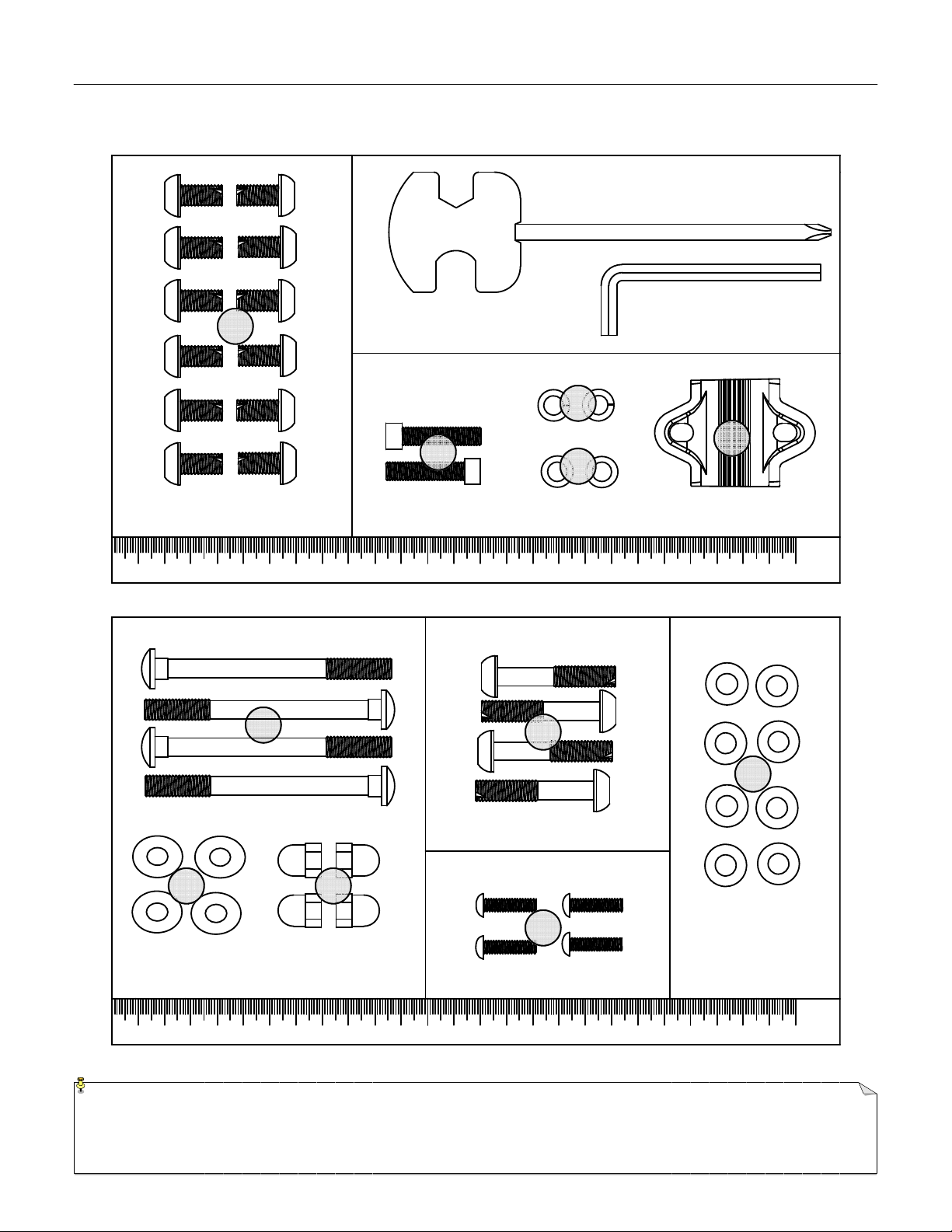
NOTE: Most of the listed assembly hardware has been packaged separately, but some hardware items have been preinstalled inthe identified
assembly parts. In these instances, simply remove and reinstall the hardware as assembly is required. Please reference the individual assembly
steps and make note of all preinstalled hardware.
HARDWARE PACK
26
(MM)
260
250
240230220210
200
190
170 180
160
150
140
130
120
1101009080
7060
50
40
302010
(MM)
260
250240230220
210
200
190
170 180160
150
140
130
120
110
1009080
7060
50
4030
20
10
31 28
29
27
33
34
16
30
32
15

P
ARTS
R
EFERENCE
4705 A
SSEMBLY
P
AR S
L
IS ING
I
TEM
# P
ART
N
UMBER
D
ESCRIPTION
QTY.
1 N/A Main Base Assembly 1
2 ST23946 Front Stabilizer Assembly 1
3 ST23947 Rear Stabilizer Assembly 1
4 ST03159-L Left Pedal 1
5 ST03159-R Right Pedal 1
6 ST03214 Seat 1
7 ST03215 Seat Back Pad 1
8 ST05952 Pop-Pin 1
9 ST13110-1 Handlebar Assembly 1
10 ST13384 Seat Support 1
11 ST13385 Seat Slider 1
12 ST05508-1 Computer Back Cover 1
13 ST23944 Computer Mast Assembly 1
14 ST13307 Handlebar (H-shaped) 1
15 01460 Truss Screw (Magazine Rack mounting) 4
16 ST13082 Handlebar Mounting Clamp 1
17 ST10159 Computer 1
18 12385 Upper Heart Rate Sensor Cable 1
19 12055 Lower Heart Rate Sensor Cable 1
20 12386 Upper Data Cable Assembly 1
21 12202 Lower Data Cable Assembly 1
22 12002 Heart Rate Cable (Seat Rail) 1
23 ST31049 Bottle Cage 1
24 ST31050 Sports Bottle 1
25 14021 AC Adapter 1
26 ST01653-2 Carriage Bolt (M8 x 90mm L) 4
27 01453 Flat Washer (8 x 16 x 2t) 12
28 ST01015-1 Acorn Nut M8 4
29 02322 Allen Bolt (M8 x 45mmL) 4
NOTE: Most of the listed assembly hardware has been packaged separately, but some hardware items have been preinstalled inthe identified
assembly parts. In these instances, simply remove and reinstall the hardware as assembly is required. Please reference the individual assembly
steps and make note of all preinstalled hardware.
P
AGE
3

P
ARTS
R
EFERENCE
4705 A
SSEMBLY
P
AR S
L
IS ING
I
TEM
# P
ART
N
UMBER
D
ESCRIPTION
QTY.
30 ST02066 Allen Bolt (M8 x 16mmL) 4
31 ST02065 Curved Washer (8 x 19 x 2t) 4
32 ST01039 Allen Bolt (M7 x 1.0 x 30mmL) 2
33 ST01056 Spring Washer (7 x 2t) 2
34 ST01052 Flat Washer (7 x 12 x 1t) 2
35 01041 Truss Screw (Computer Mounting) 4
36 01043 Truss Screw (Sports Bottle Mounting) 2
37 05710 Plastic Handle Bar Mount Cover 1
38 ST01744-1 3 IN 1 Bolt 4
39 ST07145-1 Magazine Rack 1
40 ST07398 Console Mast Boot 1
41 ST02615 Truss Screw 3
42 ST01383 Flat Washer (8 x 16 x 1t) 4
P
AGE
4
Table of contents
Popular Exercise Bike manuals by other brands


Sunny Health & Fitness
Sunny Health & Fitness SF-B121021 user manual

Monark
Monark 827E instruction manual

Stamina
Stamina 1310 owner's manual

American Fitness
American Fitness SPR-BK1072A owner's manual
 Service manual")
Cateye
Cateye CS-1000 (CYCLO SIMULATOR) Service manual

BH FITNESS
BH FITNESS H9158H Instructions for assembly and use