ST Group ST 100 User manual

ST 100
NEARFIELD SEARCH RECEIVER
USER MANUAL
ST Group, Ltd.
St. Petersburg, Russia
+7 (812) 412-3321
info@smersh.pro
www. spymarket.com

Contents
1
CONTENTS
1
General information………………………………………….…………………………………………….…
3
1.1
Purpose and Capabilities………………………..…………………….…………………………………………………………………
3
1.2
The Kit….……………………………………………………………………………………………………………………………………......
4
1.3
Description of Components………………………………………………………………………………………………………………
5
1.4
Power supply……………………………………………………………………………………………………………………………………
7
1.5
Specifications……………………………………………………………………………………………………………………………………
8
2
Interface Settings…………….……………………………………………………………………………….
9
2.1
Turning on/off……..……………………………………………………………………………………………………………………………
9
2.2
The Main Menu…………………………………………………………..………………………………………………………………….…
9
2.3
Information Line………………………………………………………………………………………………………………………..…….
10
2.4
Settings (SERVICE Mode)…….….………………………………………………………………………………………………………
10
3
Channel#1. SEARCH RECEIVER (20 MHz - 6 GHz)…………………………………………………..
12
3.1
PANORAMA mode ……………..…………………………………………………………………………………………………………….
13
3.2
DIFFERENTIAL mode ………………………………………………………………………………………………………………………
14
3.2.1
SIGNAL ANALYSIS AT A FIXED FREQUENCY function….………………………………..………………………………
15
3.2.2
SETTING "0" function……………………………………………………………………………………………………………………
17
3.2.3
OSCILLOSCOPE function …………………………………………………………………………………………………………………
17
3.2.4
SEARCH FOR VIDEO CAMERA SIGNALS function……………………………………………………………………………
18
3.3
LOCALIZATION mode ………………………………………………………………………………………………………………………
18
3.4
AUTOMATED mode…………………………………………………..………………………………………………………..……………
19
3.4.1
FREQUENCY TUNING function……………………………………………………………………………………………….…………
21
3.4.2
SEARCH FOR VIDEO CAMERA SIGNALS function ………….……………………………………………………………..
22
3.4.3
OSCILLOSCOPE function ……………………………………………………………………………………………………….……….
22
3.4.4
SETTING "0" function ……………..…………………………………………………………………………………………….……….
22
4
Channel#2. SEARCH RECEIVER (6 GHz - 12 GHz) ……………………………..…………..………
23
5
Channel#3. SEARCH RECEIVER FOR MONITORING THE SELECTED RANGES….……..……
24
5.1
MOBILE DEVICES mode …………………………………………………………………………………………………………….……
25
5.2
BASE STATIONS mode………………….…………………………………………………………………………………………………
26
5.3
USER LIST mode………………………………………………………………………………………………………………………………
26
5.4
ANALYSIS OF THE DETECTED SIGNAL function………….………………………………….………………………………
27
5.5
GAIN SETTING function ………………………………………………………………………………….………………………………
29
6
Channel#4. INFRARED DETECTOR…………………………..……………………………………………
30
6.1
DIFFERENTIAL Mode……………………..…………………………………………………………………………………………………
31
7
Channel#5. PARAMETRIC DETECTOR ……….……..…………………………………………………..
32
8
Recommendations For Use ………………………………………………………..……………………….
35
8.1
Recommendations for using the SEARCH RECEIVER (20 MHz - 6 GHz and 6 GHz - 12 GHz)………
35
8.1.1
Search in AUTOMATED mode ………………………………………………………………………………………………………….
35
8.1.2
Search in the PANORAMA mode and in the DIFFERENTIAL mode……………………….……………………….
36
8.1.3
Signal source localization…………………………………………………………………………………………………………………
36
8.2
Recommendations for using the Channel #3 (SELECTED RANGES)………………………………………………
40
8.2.1
Search for signals in the selected ranges ………………………………………………………………………………………
41

Contents
2
8.2.2
Signal source localization…………………………………………………………………………………………………………………
42
8.3
Recommendations for using an INFRARED DETECTOR………………………………………………………………….
42
8.3.1
Search for signals………………………………………………………………………………………………….…………………………
42
8.3.2
Selection of "FALSE" signals ……………………………………………………………………………………………………………
43
8.4
Recommendations for using parametric detector………………………………………………………………………..
43
9
Software………………………………………………………………………………………………………..…
44
9.1
Purpose………………………………………………………………………………………………………………………………………….
44
9.2
Functionality ………………………………………………………………………………………………………………………………..….
44
9.3
PC system requirements………………………………………………………………………………………………………………..
44
9.4
Installation………………………………………………………………………………………………………………………………………
44
9.5
SELECTED RANGES mode………………………………………………………………………………………………………………..
46
9.6
MOBILE DEVICES mode ……………………………………………………………………….…………………………………………
48
9.7
BASE STATIONS mode ……………………………………………………………………………………………………………………
51
9.8
USER LIST mode………………………………………………………………………………………………………………………………
51
9.9
FIRMWARE UPDATE……………………………………………………………………………………………………………………….…
51
10
Reference Information……………………………………………………………………………………….
53
Controls………………………………………………………………………………………………………………..………………………….
53
Initial settings………………………..…………………………………………………………………………………………………………
53
Channel#1. SEARCH RECEIVER (20 MHz - 6 GHz)………..…………………………………….……………………….
54
Channel#2. SEARCH RECEIVER (6 GHz - 12 GHz)……..…………………………………………………………………
56
Channel#3. SEARCH RECEIVER FOR MONITORING THE SELECTED RANGES………………………………
58
Channel#4. INFRARED DETECTOR………………………………………………………………………………………………….
59
Channel#5. PARAMETRIC DETECTOR………………………………………………………………………………………………
60

General information
3
1. GENERAL INFORMATION
The manual describes the principle of operation of the ST 100 (hereinafter "ST 100" or "Device").
The manual contains hyperlinks that allow you to go to the text fragments of interest.
1.1. PURPOSE AND CAPABILITIES
ST 100 is designed to search, identify and localize wireless eavesdropping devices.
Functionally the ST 100 consists of five components ("CHANNELS"):
1. CHANNEL#1 - SEARCH RECEIVER (20 MHz - 6 GHz).
2. CHANNEL#2 - SEARCH RECEIVER (6 GHz –12 GHz).
3. CHANNEL#3 - SEARCH RECEIVER FOR MONITORING THE SELECTED RANGES (hereinafter
in the text SELECTED RANGES). The term "SELECTED RANGES" refers to the frequency
ranges of digital communications (GSM, LTE, Bluetooth, WiFi, etc.) and frequency ranges
defined by the user.
4. CHANNEL#4 - INFRARED DETECTOR - designed to detect IR transmitters (eavesdropping
devices using the IR frequency range for transmission).
5. CHANNEL#5 - PARAMETRIC DETECTOR - designed to detect active digital electronic devices
(including those without a transmission channel).
Functionality:
1. Search and localization of radio transmitting eavesdropping devices:
radio microphones, telephone radio repeaters, radio stethoscopes, etc .;
video cameras with a radio channel;
radio beacons of tracking systems.
2. Identification of digital protocols (GSM, CDMA, Bluetooth, LTE, WiFi) of the detected radio
signals.
3. Identification of base stations signals and mobile digital communication devices.
4. Identification of radio signals from analogue television cameras.
5. Search for eavesdropping devices transmitting information in the infrared range.
6. Search for working electronic digital devices.

General information
4
1.2. THE KIT
1.
Main unit …………………………………………………………….…………………………………………………
1
2.
Telescopic antenna ……………………………………………………….………………………………………
1
3.
USB flash drive ……………………………………………………………………………………………….……
1
4.
Headphones……………………………………….…………………………………………………………….……
1
5.
Charger for the main unit …………………………………………………………………………………..
1
6.
Cable for connecting the main unit to the USB port of the PC …………………………..
1
7.
Parametric detector ST 100 P……………………………………………………………………………….
1
8.
Screws for attaching the parametric detector to the main unit.…………………………
1
9.
Mini-antenna.…………………………………………………………………………….……………….…………
1
10.
Case ………………………………………………………………………………………………………………………
1
Fig.1
For transportation and storage of the ST 100 the shockproof case is used.

General information
5
Fig.2
Numbers indicate the elements of the kit, laid in a certain place of the lodgment.
The designations correspond to the numbering presented in item 1.2.
1.3. DESCRIPTION OF COMPONENTS
1.3.1. MAIN UNIT
Purpose of the main unit:
•analysis of received signals;
•information display;
•control of operating modes.
Main unit components:
•module for receiving and processing signals;
•display module;
•power supply module;
•governing bodies.
The main unit is shown in Fig. 3.

General information
6
Fig.3
In fig.3
Component
1
Display
2
Keyboard
3
Power switch / volume control
4
Headphone jack
5
Parametric detector connector
6
IR detector sensor
7
Antenna connector
8
Support
9
Serial number plate
10
Connectors for attaching a parametric detector
11
Built-in speaker
12
Charger connection indicator
13
Charger socket
14
Mini-USB connector for PC connection

General information
7
1.3.2. RECEIVERS ANTENNAS
For the operation of receivers, a telescopic (Fig.1, item 2) and mini-antenna (Fig.1, item 9) are
used.
It is recommended to use a telescopic antenna to receive signals in the range of 20 MHz ÷ 3
GHz. It is recommended to use a mini-antenna to receive signals in the range of 2 GHz ÷ 6 GHz.
Any of these antennas can be used to receive signals in the range of 2 GHz ÷ 3 GHz.
Antennas are connected to the ANT socket on the top panel of the main unit (Fig.3, item 5).
1.3.3. PARAMETRIC DETECTOR ST 100P
ST 100P is a transceiver device that detects the modulation of the reflected RF sounding signal
caused by low-frequency processes in working electronic devices.
The analysis of the detected signals is carried out on the basis of the acoustic information
heard in the headphones.
1.3.4. MINI-USB CABLE
The cable (Fig.1, item 6) is used to connect the main unit to the USB port of the PC.
1.3.5. PLAYER OF THE TEST SOUND (PTS). The player is not included in the Kit.
A player is required to search for eavesdropping devices. Any portable device equipped with a
speaker (smartphone, tablet, voice recorder) can be used. Purpose of the PTS:
creation of an acoustic signal (the correlation of this signal and the information obtained
using the ST 100 means that there is an active eavesdropping device with an unencrypted
transmission channel in the tested room);
forced inclusion of eavesdropping devices equipped with a VOX activation system;
localization of detected eavesdropping devices;
creation of the "masking noise" during the search operations.
MP3 files recorded on the USB flash drive. The user can use their own files (noise in the office,
people talking, music, etc.).
1.3.6. USB FLASH DRIVE
MP3 files (for PTS), this Manual and the ST 100 software recorded on the USB flash drive.
1.4. POWER SUPPLY
The device operates on a built-in battery, the charge level of which displayed using an
indicator in the information line (Fig.6, item 3). A fully charged battery provides 7 hours of
operation. The battery charged using a charger (Fig.1, item 5).
To do this, insert the charger plug into the socket on the side panel (Fig.3, item 12) and
connect the charger to the 220V/50Hz.
Charging is accompanied by a red or orange glow of the charger connection indicator (Fig.3,
item 11) on the side panel of the device. Full charging time is no more than 7 hours. When
charging is complete, the indicator will turn green.
It is allowed to use the device while charging the battery. In this case, the time required to
fully charge the device increases.

General information
8
1.5. SPECIFICATIONS
SEARCH RECEIVER (20 МГц – 6 ГГц)
frequency range, MHz
20…6000
bandwidth, MHz
0,1/1/20
demodulation
FM
input impedance, Ohm
50
scanning speed, GHz/sec
18
uneven frequency response, dB
±6
minimum level of the detected signal, dB
-70
dynamic range, dB
50
gain control (fixed values), dB
0, 8, 16, 24, 32, 40
antenna
external
SEARCH RECEIVER (6 ГГц – 12 ГГц)
frequency range, MHz
6000…12000
bandwidth, MHz
20
scanning speed, GHz/sec
18
uneven frequency response, dB
±3
minimum level of the detected signal, dB
-50
dynamic range, dB
50
antenna
built-in
IR DETECTOR
spectral range, μm
0,75…1,1
detection bandwidth, MHz
5
angle of view, degrees
±20
minimum detectable signal strength, W/Hz1/2
10-13
PARAMETRIC DETECTOR ST 100P
frequency range, MHz
2000…2100
emitted signal level, dBm
20
antenna directional diagram, deg
90
antenna polarization
elliptical
POWER SUPPLY
built-in lithium-polymer accumulator with voltage, V
3,7
power consumption, W
<1
continuous operation time at max. power consumption, hour
>4
charging time of a fully discharged battery, hour
7
WEIGHT AND DIMENSIONS
main unit dimensions, mm
165 х 100 х 40
main unit weight, kg
0,47
dimensions of the parametric detector, mm
99 х 83 х 29
parametric detector weight, kg
0,1
case dimensions, mm
360 х 255 х 195
kit weight in a case, kg
4,73
Interface settings
9
2. INTERFACE SETTINGS
2.1. TURNING ON/OFF
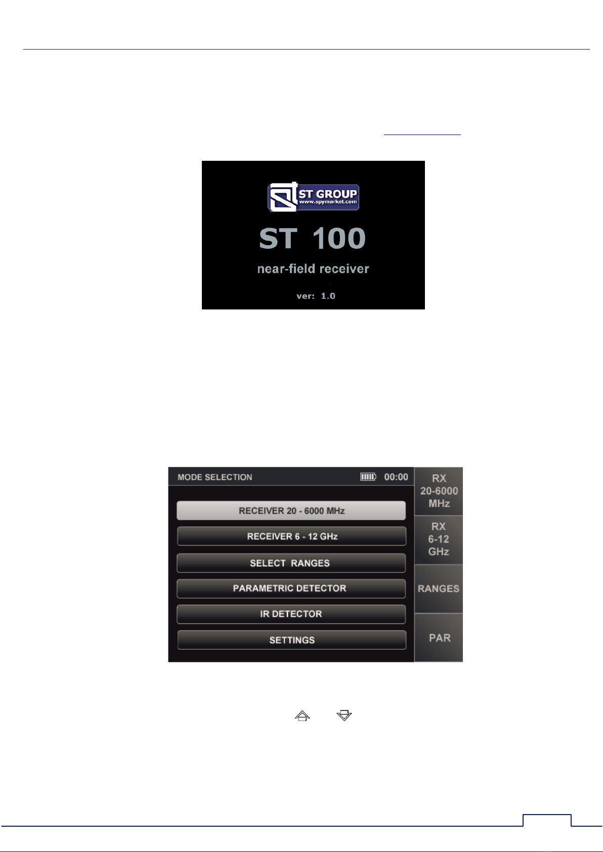
The device is turned on/off using the volume control knob (Fig.3, item 3). Screen view is in
Fig.4.
Fig.4
On the screen: company logo, device name (ST 100) and firmware version. It is necessary to
press any button on the keyboard for continue.
2.2. THE MAIN MENU
The MAIN MENU is shown in Fig.5
Fig.5
To turn on any of the menu items, use the and buttons to place the table cursor on the
corresponding line and press the ENTER.
To turn on SEARCH RECEIVER (20 - 6000 MHz), SEARCH RECEIVER (6 - 12 GHz), SELECTED
RANGES, PARAMETRIC DETECTOR you can use the buttons (F1, F2, F3, F4, respectively).
The SETTINGS menu item is intended to turn on the SERVICE mode (system settings).

Interface settings
10
2.3. INFORMATION LINE
In the upper part of the screen, there is an information line (Fig.6).
Fig.6
In Fig.6:
1
-
Channel is on
2
-
Videocamera signal detection indicator
3
-
Accumulator charge level
4
-
Current time in a format "HH:MM"
2.4. SETTINGS (SERVICE MODE)
This mode is design to set the date, time and interface language (Russian or English).
To turn on the mode, use the or buttons or in the MAIN MENU to set the tabular cursor to
the item SETTINGS and press ENTER.
For exit to the MAIN MENU, press ESC. Confirmed parameter changes after exiting the
SETTINGS mode are saved, including when the power is turned off.
The screen of the SETTINGS mode is shown in Fig.7.
Fig.7
Interface settings
11
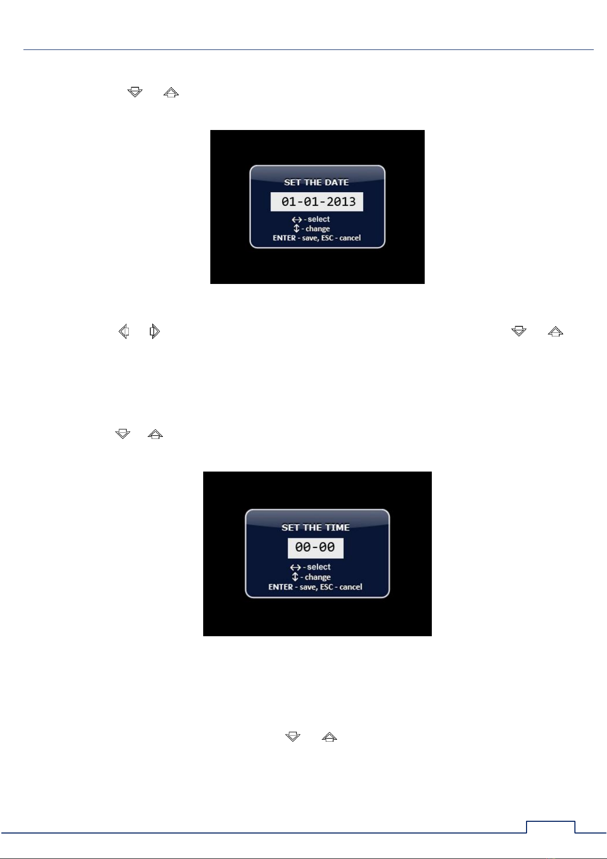
2.4.1. DATE SETTING
Using the or buttons, set the cursor to the "DATE" item and press ENTER. The date
setting menu (Fig.8) in the "DD-MM-YYY" format will appear on the screen.
Fig.8
Use the or buttons to set the cursor to the "DAY" menu item and use the or
buttons to set the desired value. The values "MONTH" and "YEAR" are set in the same method.
To confirm the set values, press ENTER. Exit from the SETTINGS mode without save the
changes - ESC.
2.4.2. TIME SETTING
Use the or buttons to set the cursor to the "TIME" menu item and press ENTER.
The time setting menu (Fig.9) in the "HH:MM" format will appear on the screen.
Fig.9
The time setting is carried out by analogy with the date setting (item 2.4.1).
2.4.3. INTERFACE LANGUAGE SETTING
To set the interface language, use the or buttons set the cursor on the "ENGLISH"
menu item and press ENTER. The interface language will change from Russian to English.
To choose the Russian language set the cursor on the item "РУССКИЙ ЯЗЫК" and press
ENTER.

Channel#1. SEARCH RECEIVER (20 MHz - 6 CHz)
12
3. CHANNEL#1. SEARCH RECEIVER (20 MHZ - 6 GHZ)
The channel is designed to detect radio signals of analog and digital radio transmitting
eavesdropping devices in the 20 MHz -6 GHz range.
To receive radio signals, two antennas are used: a telescopic antenna (Fig.1, item 2) and a
mini-antenna (Fig.1, item 9). It is recommended to use the telescopic antenna for receiving
signals in the range of 20 MHz - 3 GHz.
The mini-antenna is recommended for receiving signals in the 2 GHz - 6 GHz range.
Any of these antennas can be used to receive signals in the 2 GHz - 3 GHz range.
Antennas are connected to the ANT socket located on the top panel (Fig. 10).
Fig.10
The analysis of the detected signals is performed using:
graphic information (spectrogram, oscillogram, table of signals);
acoustic information (headphones or built-in speaker).
Channel functional diagram
Fig.11
Channel#1. SEARCH RECEIVER (20 MHz - 6 CHz)
13
MODES:
PANORAMA mode
DIFFERENTIAL mode
AUTOMATED mode
LOCALIZATION Mode
3.1. PANORAMA MODE
Functionality:
signal analysis in AUTOMATED mode;
signal analysis in DIFFERENTIAL mode;
search for a signal source using the LOCALIZATION mode;
analysis of a signal at a fixed frequency;
gain adjustment;
changing the view bar.
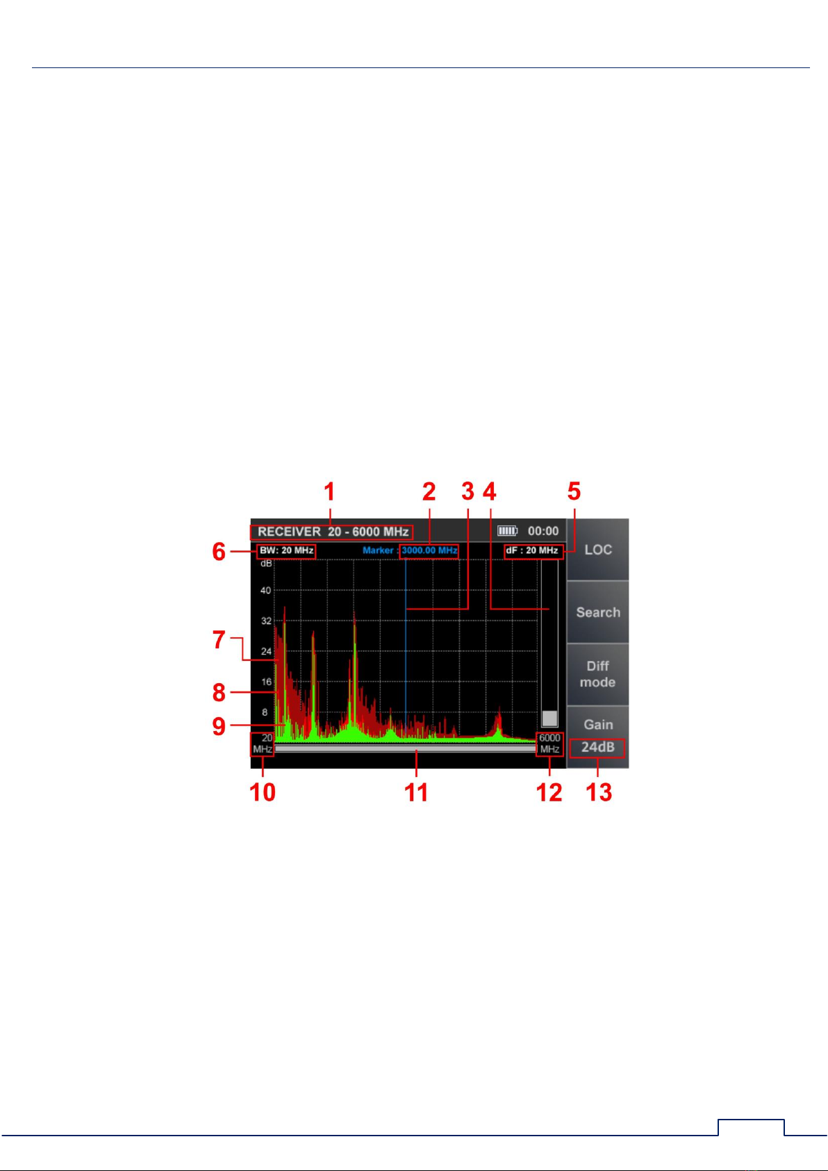
The PANORAMA mode is automatically started after switching on the channel. A panorama of
loading the frequency range is displayed on the screen (Fig.12).
Fig.12
In Fig.12:
1
-
SEARCH RECEIVER (20 MHz - 6 GHz) is on
2
-
The value of the frequency at which the marker is set
3
-
Marker
4
-
Signal level at the marker frequency
5
-
Scan step value
6
-
Bandwidth
7
-
The maximum signal level at this frequency for all cycles (burgundy)
8
-
Pulse signals detected on the last cycle (red)
9
-
Continuous signals detected on the last cycle (green)
10
-
Lower limit of the set swath

Channel#1. SEARCH RECEIVER (20 MHz - 6 CHz)
14
11
-
Scroll bar
12
-
Upper limit of the set swath
13
-
Set gain value
Controls:
Button
Action
ESC, MODE
Switch to MAIN MENU
ENTER
Turn on SIGNAL ANALYSIS AT A FIXED FREQUENCY function
Marker control
Scaling a panorama relative to a marker
F1
Turn on LOCALIZATION mode
F2
Turn on AUTOMATED mode
F3
Turn on DIFFERENTIAL mode
F4
Turn on/off SETTING THE GAIN
FUNC
Not use
Gain setting:
1. Press F4. The Gain button field will become lighter.
2. Use the and buttons to set the gain in dB (0, 8, 16, 24, 32, 40). The set value is
displayed on the indicator (Fig.13).
3. Press F4. The Gain button field will become darker.
Fig.13
ATT ENTION! Until the gain setting is completed, other modes and functions are unavailable,
except for switching to the MAIN MENU (by pressing the MODE button).
3.2. DIFFERENTIAL MODE
In DIFFERENTIAL mode, the signal levels obtained in the previous scans in PANORAMA mode
are taken as "0" and only signals with a higher level are displayed on the screen (differential
panorama).
DIFFERENTIAL mode can be used to select signals whose sources are located in the tested
room from external signals.

Channel#1. SEARCH RECEIVER (20 MHz - 6 CHz)
15
DIFFERENTIAL mode is turn on from the PANORAMA mode (Fig.12) by pressing the F3 button,
the field of which will become lighter. The device screen is shown in Fig.14.
Fig.14
In Fig.14:
1
-
SEARCH RECEIVER (20 MHz - 6 GHz) is on
2
-
Indication of turn on of the DIFFERENTIAL mode
3
-
Constant differential signal detected in the last scan cycle (purple)
4
-
Pulse difference signal detected in the last scan cycle (yellow)
5
-
Maximum signal level (at this frequency) for all cycles (burgundy)
Functionality:
search in AUTOMATED mode;
using LOCALIZATION mode;
signal analysis at a fixed frequency;
gain adjustment;
change the view bar.
DIFFERENTIAL mode controls similar PANORAMA mode controls (item 3.1).
Turning off the DIFFERENTIAL mode and switching to the PANORAMA mode is made by
pressing the F3 button, the field of which will become darker. The gain and range values set in
DIFFERENTIAL mode are retained.
3.2.1. SIGNAL ANALYSIS AT A FIXED FREQUENCY FUNCTION
The function is designed to analyze signals detected in PANORAMA mode, DIFFERENTIAL mode
and LOCALIZATION mode.
To turn on the function in PANORAMA or DIFFERENTIAL mode, use the and buttons to set
the marker to the signal of interest and press the ENTER button;
To turn on the function in the LOCALIZATION mode, use the and buttons to position
the cursor on the signal of interest and press ENTER.

Channel#1. SEARCH RECEIVER (20 MHz - 6 CHz)
16
The screen view is shown in Fig.15.
Fig.15
In Fig.15:
1
-
SEARCH RECEIVER (20 MHz - 6 GHz) is on
2
-
Signal level on fixed frequency
3
-
SETTING "0" function indicator
4
-
Bandwidth value
5
-
OSCILLOSCOPE function indicator
Functionality:
tuning to the frequency of the detected signal;
bandwidth change (100 KHz, 1 MHz, 20 MHz);
ability to use FM demodulator;
listening to demodulated signal;
signal analysis with an oscilloscope;
localization of the signal source by the energy method.
Controls:
Button
Action
ESC, ENTER
Turn off the function (return to the previous mode)
MODE
Switch to MAIN MENU
Marker control
F1
Turn on SETTING "0" function
F2
Setting the bandwidth and turning on the FM demodulator
F3
Turn on OSCILLOSCOPE function
F4
Turn on/off gain setting
FUNC
Not used
Turn off the function (switch to previous mode) by pressing ENTER or ESC.

Channel#1. SEARCH RECEIVER (20 MHz - 6 CHz)
17
3.2.2. SETTING "0"FUNCTION
The function is intended to localize the signal source detected when using the SIGNAL
ANALYSIS AT A FIXED FREQUENCY function.
The use of this function is especially effective when searching for sources of strong signals,
when even with the minimum value of the gain the signal level indicator goes off scale and the
localization of the signal source is difficult. After turned on the function, the signal level at the
fixed frequency is zeroed and the difference level is displayed on the indicator.
To turn on the function, press the F1, the field of button will become lighter.
When using the SETTING "0" function, it is possible to:
change the bandwidth value (F2);
turn on OSCILLOSCOPE (F3);
change the gain value (F4).
To turn off the function, press the F1 again. The F1 button field will become darker.
3.2.3. OSCILLOSCOPE FUNCTION
The OSCILLOSCOPE function is available when using:
SIGNAL ANALYSIS AT A FIXED FREQUENCY function
SETTING "0" function
AUTOMATED mode
To turn on the OSCILLOSCOPE, press F3. OSC button will become lighter. The screen view is
shown in Fig.16.
Fig.16

Channel#1. SEARCH RECEIVER (20 MHz - 6 CHz)
18
In Fig.16:
1
-
SEARCH RECEIVER (20 MHz - 6 GHz) is on
2
-
Fixed frequency
3
-
Time division value
4
-
Oscillogram of the demodulated signal at a fixed frequency
5
-
Activity indicator OSCILLOSCOPE function
Functionality:
determination of the time parameters of the demodulated signal;
changing the scale of the time axis;
changing the bandwidth value;
gain adjustment.
Controls:
Button
Action
ESC, F3
Turn off OSCILLOSCOPE function
MODE
Switch to MAIN MENU
Changing the horizontal division value 100μS/200μS/500μS/1mS/2mS/5mS/10mS
F2
Setting the bandwidth and turning on the FM demodulator
F4
Turn on/off gain setting
FUNC, F1
ENTER
Not used
To turn off the OSCILLOGRAPH function, press the F3 or ESC.
3.2.4. SEARCH FOR VIDEO CAMERA SIGNALS FUNCTION
When moving the marker, the parameters of each detected signal are analyzed for their
correspondence to the parameters of the signals from video cameras. If the comparison is
positive, the video camera detection indicator appears in the information line (Fig.6, item 2).
3.3. LOCALIZATION MODE
The mode is intended for localization of radio signal sources in the tested room. Moving around
the room, the user observes the change in the levels of several of the most powerful signals.
In the mode, an adaptive change in the receiver gain is implemented. This increases the
reliability of localizing the signal source.
The device monitors the increase, decrease and maximum values of signal levels relative to
the levels obtained when the mode was turned on. This makes it possible to determine the
position of the user relative to the signal source.
The mode allows you to distinguish external signals from signals, sources of which are located
in the tested room.
Turning on the LOCALIZATION mode is possible from the PANORAMA mode or DIFFERENTIAL
mode by pressing F1. The screen view is shown in Fig.17.

Channel#1. SEARCH RECEIVER (20 MHz - 6 CHz)
19
Fig.17
In Fig.17:
1
-
SEARCH RECEIVER (20 MHz - 6 GHz) is on
2
-
Quantity of signals detected
3
-
Table cursor
4
-
Detected signal number
5
-
Signal frequency
6
-
The current signal level, the value of which is lower than the level detected when the
device was turned on ("0" level)
7
-
Current signal level (green)
8
-
The maximum signal level detected for the entire current session (burgundy).
3.4. AUTOMATED MODE
AUTOMATED mode detects signals whose amplitude exceeds the adaptive detection threshold.
The mode is turn on from DIFFERENTIAL mode or PANORAMA mode by pressing F2 button. The
search for signals is performed within the established range, taking into account the results
obtained in the DIFFERENTIAL mode (if the AUTOMATED mode was switched on from the
DIFFERENTIAL mode). All detected signals are assigned one of three attributes.
The default is:
"NON-DANGEROUS" - signals from base stations of mobile communication systems;
"DANGEROUS" - signals of wireless mobile devices;
"UNKNOWN" - all other signals.
The ST 100 software allows you to assign a "DANGEROUS" or "NON-DANGEROUS" attribute to
certain frequency bands.
Table of contents


