ST STV674/502V-R01 Quick start guide

USER MANUAL
July 2004 1/20
STV674/502V-R01
USB Flash Drive Camera
User Notes
This document details the contents and operation of the STV0674 FlashBoard evaluationkit. It may beused
as a reference to allow the generation of user manuals for products based on this design.
Order Codes
Table 1: Order Codes
Part Number Description
STV-674/502V-R01 STV0674 USB Flash Drive board featuring the miniature
VS6502VF lensed VGA color CMOS sensor module
STV0674T100 Digital video co-processor (100TQFP package)
VS6502V015/T2 VGA CMOS color image sensor module

2/20
STV674/502V-R01
Contents
Chapter 1 Introduction . . . . . . . . . . . . . . . . . . . . . . . . . . . . . . . . . . . . . . . . . . . . . . . . . . . . . .3
1.1 Key Features . . . . . . . . . . . . . . . . . . . . . . . . . . . . . . . . . . . . . . . . . . . . . . . . . . . . . . . . . . . . 3
Chapter 2 Minimum System Requirements . . . . . . . . . . . . . . . . . . . . . . . . . . . . . . . . . . . . . .4
Webcam mode . . . . . . . . . . . . . . . . . . . . . . . . . . . . . . . . . . . . . . . . . . . . . . . . . . . . . . . . . . 4
NMS mode . . . . . . . . . . . . . . . . . . . . . . . . . . . . . . . . . . . . . . . . . . . . . . . . . . . . . . . . . . . . . 4
Chapter 3 Basic Camera Operation . . . . . . . . . . . . . . . . . . . . . . . . . . . . . . . . . . . . . . . . . . . .5
3.1 Untethered Operation . . . . . . . . . . . . . . . . . . . . . . . . . . . . . . . . . . . . . . . . . . . . . . . . . . . . . 6
3.2 Tethered Operation . . . . . . . . . . . . . . . . . . . . . . . . . . . . . . . . . . . . . . . . . . . . . . . . . . . . . . . 7
Chapter 4 Software Installation . . . . . . . . . . . . . . . . . . . . . . . . . . . . . . . . . . . . . . . . . . . . . . .8
4.1 NMS mode . . . . . . . . . . . . . . . . . . . . . . . . . . . . . . . . . . . . . . . . . . . . . . . . . . . . . . . . . . . . . 8
4.2 Webcam mode . . . . . . . . . . . . . . . . . . . . . . . . . . . . . . . . . . . . . . . . . . . . . . . . . . . . . . . . . . 8
Chapter 5 DirectCap . . . . . . . . . . . . . . . . . . . . . . . . . . . . . . . . . . . . . . . . . . . . . . . . . . . . . . .10
5.1 Video / Audio device . . . . . . . . . . . . . . . . . . . . . . . . . . . . . . . . . . . . . . . . . . . . . . . . . . . . . 10
5.2 File Menu . . . . . . . . . . . . . . . . . . . . . . . . . . . . . . . . . . . . . . . . . . . . . . . . . . . . . . . . . . . . . 11
5.3 Edit menu . . . . . . . . . . . . . . . . . . . . . . . . . . . . . . . . . . . . . . . . . . . . . . . . . . . . . . . . . . . . . 11
5.4 Properties menu . . . . . . . . . . . . . . . . . . . . . . . . . . . . . . . . . . . . . . . . . . . . . . . . . . . . . . . . 12
5.5 Clock menu . . . . . . . . . . . . . . . . . . . . . . . . . . . . . . . . . . . . . . . . . . . . . . . . . . . . . . . . . . . . 12
5.6 Help menu . . . . . . . . . . . . . . . . . . . . . . . . . . . . . . . . . . . . . . . . . . . . . . . . . . . . . . . . . . . . . 12
Chapter 6 AVICreate . . . . . . . . . . . . . . . . . . . . . . . . . . . . . . . . . . . . . . . . . . . . . . . . . . . . . . .13
Chapter 7 Firmware Upgrade . . . . . . . . . . . . . . . . . . . . . . . . . . . . . . . . . . . . . . . . . . . . . . . .17
Chapter 8 Firmware Identification . . . . . . . . . . . . . . . . . . . . . . . . . . . . . . . . . . . . . . . . . . . .18
Revision history . . . . . . . . . . . . . . . . . . . . . . . . . . . . . . . . . . . . . . . . . . . . . . . . . . . . . . . . . . . . . .19

Introduction STV674/502V-R01
3/20
1 Introduction
This document details the contents and operation of the STV0674 Flash Board evaluation kit. It
may be used as a reference to allow the generation of user manuals for products based on this
design.
The STV0674 Flash Board operates in two distinct modes that are selectable during “power on”:
Webcam mode
and
Native Mass Storage (NMS) mode
. This document distinguishes between
these two modes where appropriate to describe the Flash Board and associated software
operation. See Section Basic Camera Operation for details on how to select between each mode.
1.1 Key Features
WebCam Mode
●No stand-alone operation – must be plugged into USB
●DirectShow Driver Support
●Real-time video – up to 30fps VGA
●Real-time audio
●DirectCap – sample DirectShow application
NMS Mode
●Still image capture
●Movie clip capture (synchronized audio\video)
●Audio clip capture
●Flash memory format
●Behaves as removable disk drive for data storage when tethered
●~400Kbyte/s Write ~500Kbytes/s Read.
●AVICreate – application to convert movie clips to standard AVI format

s 4/20
STV674/502V-R01 Minimum System Requirements
2 Minimum System Requirements
Webcam mode
●IBM PC or compatible
●Win98SE, WinME, Win2K + SP3, WinXP + SP1 Operating System
●DirectX 8.1 or later
●Graphics Adapter capable of 800x600 resolution, 64k colours (“thousands of colours”)
●PII 266, with 64M RAM (Win98/ME) or 128MRAM (Win2K/XP)
●No support yet for Mac
NMS mode
●IBM PC or compatible
●Win98SE, WinME, Win2K + SP3, WinXP + SP1
●Mac OSX & MacOS9

Basic Camera Operation STV674/502V-R01
5/20
3 Basic Camera Operation
The STV0674 Flash Board has three buttons and 2 LEDs to provide the User Interface. LED1 is
the upper bi-colour LED. LED2 is the red LED below. The SHUTTER button is on the top of the
PCB, the MODE button is on the side and the Power On button on the front close to the
USB\Power connection.
Operation is described as “untethered” (stand-alone) when the board is not plugged into USB and
operation is controlled via the on board UI only or “tethered” when the board is connected to a PC
via USB and uses the power supplied by USB. Untethered operation requires a “AAA” battery on a
separate PCB to provide power which is connected to the main PCB via the USB connector.
Figure 1: STV0674 Flash Board

s 6/20
STV674/502V-R01 Basic Camera Operation
3.1 Untethered Operation
Ensure that the separate “AAA” battery PCB is connected.
NMS mode
For stand alone operation simply give a short press to the Power On button to switch the camera
on. It will run through an initialisation before a ‘beep’ and LED flashes once to indicate ready.
The following diagram illustrates the UI operation when untethered in NMS mode.
On each display there is a 5 second timeout after which it will revert to ‘Stills’.
●Every button press causes a ‘standard’ beep unless otherwise stated
●For file transfer green will ‘flicker’ for reads while red (LED1) will ‘flicker’ for writes
●For WebCam mode: hold MODE on power up till both LEDs are RED (buttons are disabled)
●For memory full then stop action, low beep and UI returns to stills
●Power down timeout set for 20 seconds of inactivity
●Low Battery indicated by flashing RED (LED1)
Webcam Mode
Webcam mode is available only when tethered. Please see the following section.
Figure 2: LED based UI
Press
Shutter
Take
Picture
Press Shutter to
START
Yellow Flashing
(slow)
Press Shutter to
STOP
Press Shutter to
START
Green Flashing
(slow)
Press Shutter to
STOP
Press Shutter for
Format warning
LED2
Flashing (fast)
Press Shutter to
FORMAT
LED2 Constant
(Piezo: 3
short beeps
repeating)
(Low &
high
beeps)
Beep when complete
Constant
Red Yellow
Constant Green
Constant LED2
Flashing (slow)
P/up Format
Audio
Clip
Stills Movie
Clip
MODE MODE MODE

Basic Camera Operation STV674/502V-R01
7/20
3.2 Tethered Operation
When the flash board is plugged in to USB, the firmware delays USB enumeration until the
firmware has completed its “boot up” sequence. It can enumerate in either NMS mode or Webcam
mode.
NMS mode
When connected to the PC, the flash board is set by default to NMS mode, it enumerates to use the
standard USB mass storage drivers provided by the OS.
Webcam mode
The flash board enumerates as a webcam when the MODE button is held down while the device is
plugged in to USB. The user must hold the MODE button until both LEDs have a red display.
As the webcam is a ‘Composite USB Device’, when it has successfully enumerated, it appears in
Windows Device Manager in two separate locations:
1 In the “Imaging Device” key as “NMS Video Camera (webcam)”.
2 In the “Sound, video and game controllers” key as “USB Audio Device”
Webcam mode requires ST drivers to be installed to provide the video functionality (See
Chapter 4:
Software Installation
). The audio functionality is provided by the standard Windows audio drivers.

s 8/20
STV674/502V-R01 Software Installation
4 Software Installation
4.1 NMS mode
Software driver installation is not required for all OS that natively support Mass Storage devices.
This includes all supported Mac OS and Windows versions later than Win2K.
Win98 Gold and SE do not support Mass Storage natively. It is therefore necessary to install an
additional software driver that is provided by ST in the ‘stvnms.exe’ executable installer.
Movie clips recorded in untethered NMS mode are stored in a proprietary file format with the file
extension “.stj”. An application to convert this file into a standard AVI is supplied by ST
(AVICreate). To avoid software installation problems and to maximise mobility of the Flash Board,
this application is designed to be stored on the board itself and supports all Windows OS. ST
recommends that the application is placed on the Flash Board during production and then also
supplied as part of a software installation package on CD. See
Chapter 6: AVICreate
for
information on using AVICreate. To playback AVIs created using AVICreate, an MJPG codec must
be installed. DirectX 8.1 or later includes a suitable MJPG codec. See the following section.
4.2 Webcam mode
Webcam driver installation should be performed before the camera is plugged in.
The PC is assumed to already have DirectX 8.1 or better installed.
Note: DirectX 8.1 is installed automatically with WinXP. For all other OS's, the user may have to upgrade
to v8.1 manually. ST recommends that DirectX 8.1 or later is provided on the software installation
CD. DirectX is available in a re-distributable installation from the Microsoft Website: and look for
“directx”
. Alternatively, the end user may be directed to the ‘Windows Update’ site:
windowsupdate.microsoft.com/
●Video
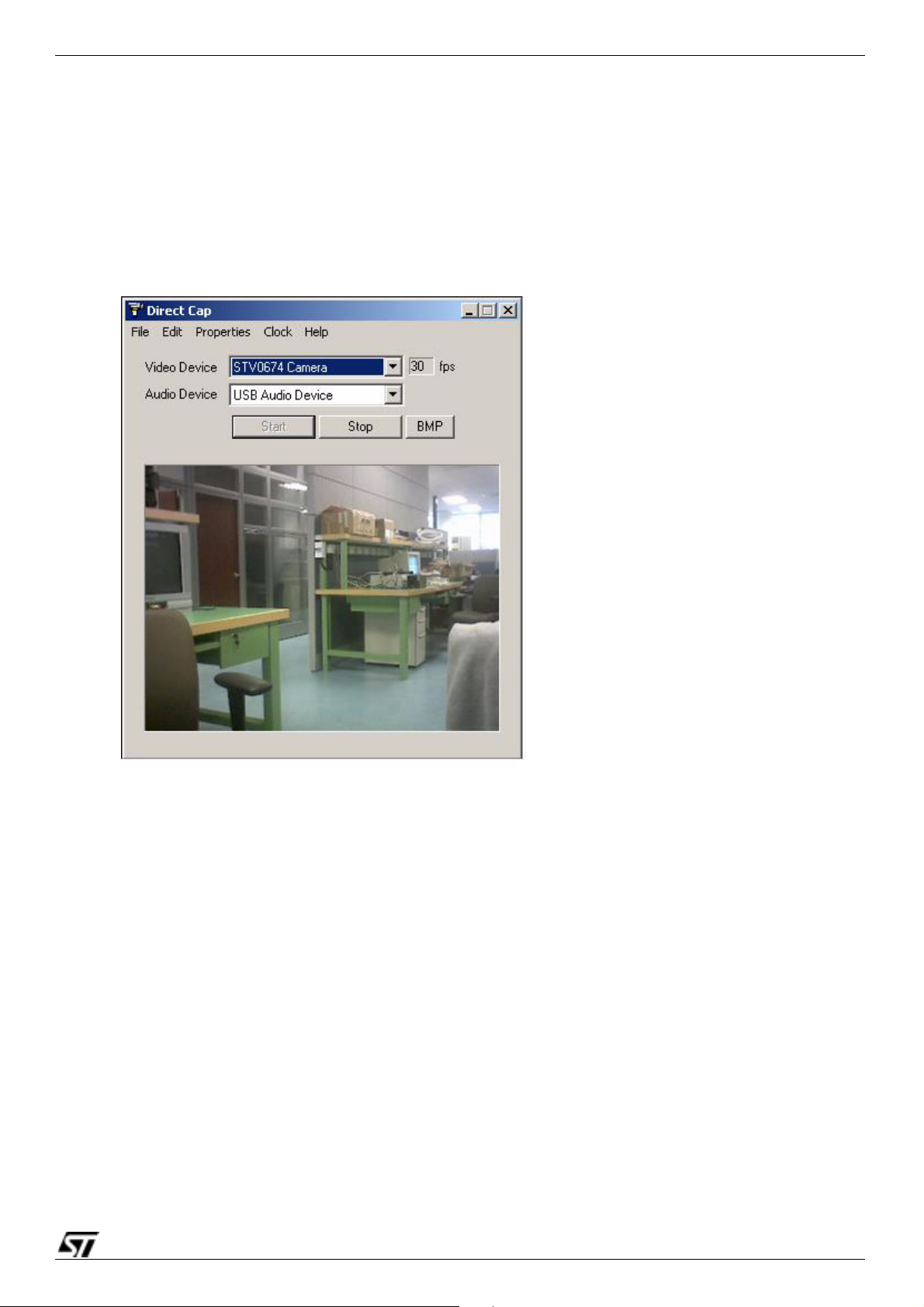
The webcam video driver is supplied in an executable installer from ST. Usually named
"dm1NNNwq.exe" where 'NNN' is the version of driver. The latest version is2-01 (dm1201wq.exe).
Double click on the executable file and follow the onscreen installation instructions.
The webcam video driver supports Microsoft's DirectShow architecture.
Video for Windows (Microsoft's legacy webcam architecture) is supported through a mapper
provided by Microsoft which is installed with the OS. Applications such as Netmeeting are
implemented using VfW.
Note: 1 The VfW mapper for WinXP does not operate correctly. This is fixed by installing WinXP service
pack 1.
2 The VfW mapper on all OS does not support the custom property pages that are implemented by
the DirectShow driver. These property pages are therefore not accessible in applications that are
written for VfW. See Properties menu for information on the property pages.

Software Installation STV674/502V-R01
9/20
●Audio
The device is compliant to the USB Audio Class specification and so uses the standard audio
drivers supplied by Microsoft. No software installation is required for audio support
Note: 1 After installing on Win98 Gold, the PC will require a reboot before the audio device may be used.
2 While installing video drivers on Win98 Gold /SE the user will be prompted for the original Win98
CD to find some files used by the DirectShow system. The user should have this CD ready and
insert it into the CDROM driver when prompted. The requested files may be found on the Win98
CD under ‘Win98se/setup/win98’ directory.

s 10/20
STV674/502V-R01 DirectCap
5 DirectCap
To demonstrate webcam mode, an application called DirectCap is provided by ST with the
STV0674 Flash Board evaluation kit. The application is supplied with its own executable installer.
Just double click on the ‘DirectCap.exe’ file and follow the onscreen instructions.
5.1 Video / Audio device
To start streaming video, select ‘NMS Video Camera’ from the pull down menu under Video Device
then press the Start button. To stop, press the Stop button.
To start streaming audio, select ‘USB Audio Device’ from the pull down menu under Audio Device
then press the Start button. To stop, press the Stop button. Note that on WinXP, the OS displays
the device name from a string in the firmware and so it appears as ‘ST’ instead of ‘USB Audio
Device’. This may be customised for OEM products.
Video and audio may be streamed simultaneously, but the ‘preview’ shows a short time lag for
audio. When streaming to file, this time lag does not occur.
To capture a still image from the video preview, press the BMP button. The picture is taken when
the button is pressed and then a dialog prompts for the user to select a filename to save the image.
Figure 3: The DirectCap window

DirectCap STV674/502V-R01
11/20
5.2 File Menu
As well as playing audio and streaming video to the screen, you can also save video AVI’s to the
HDD.
●Set Filename
Use this option prior to video streaming to select where the AVI file will be saved.
●Stream to File
This option becomes available after a filename has been selected. Once stream to file is selected,
the next time the Start button is pressed, the audio and video data is written to file until the Stop
button is pressed.
●Exit
Stops video/audio and closes the application.
5.3 Edit menu
No options are available under this menu at present.
Figure 4: The stream to file option with DirectCap

s 12/20
STV674/502V-R01 DirectCap
5.4 Properties menu
Under the properties menu, there are the standard DirectShow options to show the driver property
pages.
Video Capture Filter
This property page is supplied by the STV0674 DirectShow driver and allows the user to
manipulate standard video properties such as brightness, contrast, saturation, white balance and
banding filter (50Hz or 60Hz).
Video Capture Pin
This property page is provided by DirectX and is standard to all DirectShow drivers. It allows the
user to select options such as framerate and video resolution.
5.5 Clock menu
Not implemented at present.
5.6 Help menu
The help menu provides access to the ‘About’ box which details the application version number.
Figure 5: Driver property menu

AVICreate STV674/502V-R01
13/20
6 AVICreate
The AVICreate application is provided by ST to allow users to translate video clips that are captured
in the proprietary ‘.stj’ format into AVIs that may then be played using any standard media
application (eg. Windows Media Player).
This document describes ‘1-03’ version of the application.
The application is used in two different ways. When first run on a PC, it prompts the user to allow
‘registration’ of the application on the system as illustrated below.
It is recommended to register the application in this manner so that the system automatically
associates ‘STJ’ files with this application. A copy of the application will be made in the local
‘Program Files’ directory. The user may then directly manipulate STJ files from Windows Explorer
as described in
Section : File Association
.
If the user does not require this functionality, then they must select ‘Do not ask me again’ and click
‘No’. The application must then be run directly to convert STJs as described in
Section : File
Association
.
Once registered, the user does not need to directly run the AVICreate application. Note, however,
that the registration must be performed on each new PC that the Flash Drive is used with. It is
therefore recommended that a copy of the AVICreate application is retained in the Flash Drive
memory to allow full portability. When the Flash Drive is plugged in to a new system AVICreate
should be run once to allow registration.
Figure 6: Registration of the application

s 14/20
STV674/502V-R01 AVICreate
File Association
If AVICreate application is registered as described previously, the user may then convert STJ files
to AVI format from Windows Explorer without directly running the AVICreate application. Three
options become available to the user by right clicking on an STJ file as illustrated below.
●Open (also invoked by double clicking on the file).
The STJ will automatically be converted to AVI format. The AVI file will be created in the
current directory and will retain the same name as the original STJ but with the new AVI file
extension. The STJ file is removed after the AVI has been successfully created. The AVI file is
then automatically played by the systems default media player.
●Create AVI in My Documents.
A new AVI file is created the users ‘My Documents’ folder. The original STJ file is not altered.
●Create AVI.
The user is prompted to specify a folder where a new AVI file will be created. The original STJ
file is not altered.
Figure 7: Three options with STJ files and AVICreate

AVICreate STV674/502V-R01
15/20
Dialog Interface
If the application is not registered on the system, then it is necessary to run AVICreate directly each
time a conversion to AVI format is required. When run, the application will present the following
dialog. The dialog controls are described in
Figure 8
.
●STJ Source Location (left)
The edit box at the top left presents the location where the application looks for ‘.stj’ files to convert.
This directory defaults to be the current directory where the application is run from. The user may
change this directory by typing in a new path in the edit box or by pressing the ‘browse’ (…) button
and selecting a directory in the normal Windows fashion. When a new directory is selected, the
application will automatically update the list of ‘.stj’ files available to convert.
Source List (left)
The list in the left half of the dialog shows all the ‘.stj’ files that reside in the source location. The list
supports multiple selection in the usual Windows fashion using the ‘ctrl’ and ‘shift’ keys.
One or more files may be selected before pressing the ‘create’ button to convert to AVI file format.
Alternatively, the user may double click on a file to convert it.
●AVI Target Location (right)
The edit box at the top right presents the standard ‘My Documents’ directory as the default place to
store ‘.avi’ files that are created. The user may change this directory by typing in a new path in the
edit box or by pressing the ‘Browse’ (…) button and selecting a directory in the normal Windows
fashion. When a new directory is selected, the application will automatically update the list of ‘.avi’
files currently in the target directory.
●Target List (right)
The list in the right half of the dialog shows all the ‘.avi’ files that reside in the target location. The
list supports single selection only and the user may either double click or press the ‘Play’ button to
view the ‘.avi’ file selected.
Figure 8: Dialog controls from AVICreate

s 16/20
STV674/502V-R01 AVICreate
●Delete Original (centre)
This option allows the user to specify what happens to the original ‘.stj’ file in the source location.. If
checked, the file will be deleted and replaced with the new ‘.avi’ file. If left unchecked, the original
‘.stj’ file will remain in the source location and the user must use this application again to convert on
any new PC.
●Create (centre)
Press this button to convert all selected ‘.stj’ files in the source list to ‘.avi’s.
●Create All (centre)
Press this button to convert all the ‘.stj’ files listed in the source list to ‘.avi’s.
●Cancel (centre)
This option becomes available during ‘.avi’ creation and when pressed causes the current
operation to stop.
●Play (centre)
Press ‘Play’ to view the currently selected ‘.avi’ file in the target list.
●Exit (centre)
Quit the application.

Firmware Upgrade STV674/502V-R01
17/20
7 Firmware Upgrade
The STV0674 Flash Drive may easily be upgraded with new firmware. Each firmware update is
distributed as a PC executable file which may be downloaded from a website and requires no other
installation than the standard webcam driver.
Simply run the executable and follow the onscreen instructions. The following points should be
noted for ease of use:
●Start with no devices plugged in to the PC when you run the EXE (otherwise you will be
prompted to remove them)
●Only plug one device into the PC at a time.
●It is recommended that the device be plugged directly into the PC’s inbuilt USB ports. Avoid
using a hub during firmware upgrade.
●After upgrade, it is recommended that the device be reformatted using the UI ‘format’ option.
●If using a customised version of firmware that does not support format from the UI then format
the drive from Windows. After format, unplug without copying any files to the drive and power
up in untethered mode once before continuing operation (the drive is reformatted when
powered up for the first time when empty).

s 18/20
STV674/502V-R01 Firmware Identification
8 Firmware Identification
ST provides a simple application called ‘PatchInfo’ which may be used to display information about
the firmware patch on a device. This is designed for use by developers and test engineers only.
The application should not be included in a release software package for any devices based on the
STV0674.
The device must be connected in webcam mode for this application to work. Also, the correct
‘OEM’ must be selected before the patch information is displayed. See below.
●OEM This edit box allows the user to select which driver to use. Each customised
firmware\driver has a different OEM name. The generic USB FlashDrive included in this
package has an OEM of ‘679’. The OEM name for a particular customised driver\firmware may
be found from the name of the webcam driver files (eg. stvxxx.sys, where xxx is the OEM
name). If in doubt, contact your ST support engineer.
●Display Click this button to connect to the camera and display the patch information.
●Save. Click this button to save the current contents of the output window to file. It is useful to
include this file as part of any support query to ST.
The information displayed in the text output window may be used to identify the firmware patch. In
particular, the ‘PatchID’ is unique for every patch released from ST. A secondary verification may
be made using the build date and time.
Figure 9: Patch information

Revision history STV674/502V-R01
19/20
Revision history
Table 2: STV674/502V-R01 Revision History
Version Date Comments
0-01 18-Mar-03 Created
0-02 31-Mar-03 Updated to describe features in NMS10 firmware release
Updated to describe AVICreate v0-08
Distinguishes between RevA1 board and RevA2
0-03 22-Apr-03 Updated to include info on RevC board
0-04 30-Apr-03 Removed info on RevA board. This document now describes RevC only and is used to
accompany the salestype.
0-05 4-Jun-03 Firmware release updated to STD002
Updated support to include MacOS9
Updated to ‘dm1201xv’ webcam driver
Updated to v1-03 AVICreate
Updated to ‘clearnand2’
Includes Win98 NMS driver
Added some advisory notes for webcam driver installation on Win98
Updated to DirectCap 1-17
1-00 2-Oct-03 Includes reference to 502 SmOP board
Now uses firmware upgrade EXE
Updated to dm1202xv webcam driver
Updated to DirectCap 1-18
Included picture of flashdrive buttons\LED
1-01 13-Oct-03 Added PatchInfo application
1-02 28-Nov-03 Removed differentiation between 501\502
1-03 10-May-04 Document formatted prior to Web publication. Changes only affect the format.

20/20
STV674/502V-R01
Information furnished is believed to be accurate and reliable. However, STMicroelectronics assumes no responsibility for the consequences of use of such
information nor for any infringement of patents or other rights of third parties which may result from its use. No license is granted by implication or otherwise
under any patent or patent rights of STMicroelectronics. Specifications mentioned in this publication are subject to change without notice. This publication
supersedes and replaces all information previously supplied. STMicroelectronics products are not authorized for use as critical components in life support
devices or systems without the express written approval of STMicroelectronics.
The ST logo is a registered trademark of STMicroelectronics.
All other names are the propertiy of their respective owners
© 2004 STMicroelectronics. All Rights Reserved.
STMicroelectronics Group of Companies
Australia - Belgium - Brazil - Canada - China - Czech Republic - Finland - France - Germany - Hong Kong - India - Israel - Italy - Japan -
Malaysia - Malta - Morocco - Singapore - Spain - Sweden - Switzerland - United Kingdom - United States
http://www.st.com
Table of contents