STA-RITE 60SEP User manual

SEPARATION TANKS
OWNER’ S M A N U A L
INSTALLATION, OPERATION & PARTS
MODEL
60SEP
Pentair Water Pool and Spa, Inc.
1620 Hawkins Ave., Sanford, NC 27330 • (800) 831-7133 • (919) 566-8000
10951 West Los Angeles Ave., Moorpark, CA 93021 • (800) 831-7133 • (805) 553-5000
Visit us on the Internet @ www.pentairpool.com or www.staritepool.com
© 2009 Pentair Water Pool and Spa, Inc. Printed in U.S.A. S303 (Rev. A 4/16/09)
Furnish this manual to the end user of
this tank; its use will reduce service
calls and chance of injury and will
lengthen tank life.

2
SEPARATION TANKS
Toavoid unneeded service calls, prevent possible injuries, and get the most
out of your filter, READ THIS MANUAL CAREFULLY!
The Sta-Rite Separation Tank:
•Is designed to separate spent diatomaceous earth and other solids form
swimming pool water when backwashing your DE filter.
•Is an excellent performer; durable, reliable.
Table of Contents
Safety Instructions ...................................................................................2-3
General Information/Dimensions.................................................................4
Installation ..................................................................................................5
Operation ...................................................................................................6
Opening/Closing Tank ................................................................................6
Maintenance/Inspection ...........................................................................7-8
Winterizing.................................................................................................8
Repair Parts List...........................................................................................9
READ AND FOLLOW SAFETY
INSTRUCTIONS!
This is the safety alert symbol. When you see this symbol on your system or in
this manual, look for one of the following signal words and be alert to the
potential for personal injury.
DANGER warns about hazards that will cause serious personal injury, death or
major property damage if ignored.
WARNING warns about hazards that can cause serious personal injury, death
or major property damage if ignored.
CAUTION warns about hazards that will or can cause minor personal injury or
property damage if ignored.
The label NOTICE indicates special instructions which are important but not
related to hazards.
Carefully read and follow all safety instructions in this manual and on filter.
Keep safety labels in good condition.
Replace missing or damaged safety labels.

3
Incorrectly installed equipment may fail, causing severe injury
or property damage. Read and follow operational parameters given below
when installing equipment described in this owner’s manual.
1.Follow instructions and procedures in owner’s manual for installation,
operation, and maintenance of equipment.
2. Do not connect any part of pool or spa system to city water system, well
water system, or to any other type of high pressure water system or supply.
3. Do not attempt to use pool or spa equipment in any type of installation
other than a pool or spa.
4. Trapped air under pressure in system can cause explosion and serious in-
jury. Follow instructions in owner’s manual or on equipment to make sure
that no air is trapped in the system before testing or operating equipment.
Equipment that is incorrectly pressure tested may explode,
causing severe injury or property damage. Pressure testing should only be
done by trained pool professionals, following test parameters given below
when testing the equipment described in this owner's manual.
1. Make physical check for correct tightness of all clamps, bolts, lids, and
system accessories prior to test. See owner’s manuals covering equipment
being tested for this information.
2. Make sure there is no air entrapped in system. Release all air in system
before testing.
3. When using a Sta-Rite pump and trap, tighten trap lid to 30 ft. lbs.
(4.1 kg-m.) torque before testing.
4. Water pressure for testing must be 25 PSI (172kPa) or less.
5. Water temperature for testing must be 100°F (38°C) or less.
6. Test length must be 24 hours or less.
7. After test, make visual check of system to make sure that it is ready for
operation. Remove Sta-Rite trap lid and retighten hand-tight only.
8. Exceeding any one of limits 2 through 6 or omitting physical checks
specified in Steps 1 and 7 can result in equipment and property damage
or physical injury.
NOTICE: These parameters apply to Sta-Rite pool and spa equipment only.
For non-Sta-Rite equipment, consult manufacturer.
If filter clamps are
adjusted or removed
under pressure,
tank may explode,
causing severe injury or
major property damage.
BEFORE WORKING
ON FILTER:
1. Stop pump.
2. Open air release
valve.
3. Release all pressure
from system.
Filter pumps require
hazardous voltage
which can shock,
burn, or cause death
BEFORE WORKING
ON PUMP OR MOTOR
Disconnect power to
motor.

4
GENERAL INFORMATION
Clean a new pool as well as possible before filling pool and operating filter.
Excess dirt and large particles of foreign matter in the system can cause seri-
ous damage to the filter and pump.
Keep pool water pH at recommended level (7.2 to 7.6).
Be sure both clamps are in place and knobs are securely tightened before
starting filter. If filter is improperly disassembled or assembled, it will explode
under pressure! To avoid danger of severe injury or major property damage,
always follow service instructions in this manual when working on filter!
NEVER operate this filter system at more than 50 pounds per
square inch (50 PSI/345kPa) pressure!
On a new pool installation, we recommend:
1. Disassemble the filter after the initial cleanup.
To prevent severe injury or major property damage, follow
instructions in your filter owner’s manual.
2. Remove and hose down the element assembly to remove contaminants.
Hazardous pressure.
Can cause severe
injury or major
property damage
from tank blow up.
Release all pressure
and read instructions
before working on
separation tank.
12" DIA.
(305)
4 7/8"
(124)
29 7/8"
(759)
40 5/8"
(1032)
2" NPT
1 1/2" NPT
3"(76.2)
70"
(1778)
Figure 1 - Dimensions in inches (mm)

5
INSTALLATION - GENERAL
Installation of separation tank should only be done by qualified, licensed
personnel.
Separation tank mount must
Provide space and lighting for easy access for routine maintenance.
Provide adequate ventilation and drainage for pump.
Be protected from weather and reasonably level.
Be less than three feet above pool water level.
Be as close to pool as possible to reduce line loss from pipe friction.
Piping
All piping must conform to local and state plumbing and sanitary codes.
Never use pipe joint sealing compound on pipe and fittings that are plastic or
may come into contact with plastic. Use only Teflon®tape, Plasto-Joint Stik®
or Silastic 732®RTV on PVC pipe and fittings; pipe joint compound may
cause stress cracking of plastic components. Use pipe joint compounds only
on metal-to-metal joints.
Support pipe independently to prevent strains on filter or pump.
Use 1-1/2" (38mm) or larger pipe to reduce pressure losses.
NOTICE: Filter locations remote from pool are possible but may require larger
pipe to produce adequate flow through filter.
Check local codes if considering a remote installation.
Fittings restrict flow; for best efficiency use fewest possible fittings.
Keep piping tight and free of leaks: pump suction line leaks may cause
trapped air in filter tank or loss of prime at pump; pump discharge line leaks
may show up as dampness or jets of water.
Valves
AMulti-port Valve to allow backwash cleaning is recommended.
Arecirculation line with shutoff valve installed between pool return line and
pump suction will allow recirculation of water during precoat if you have a
precoat pot.
Electrical
BE SURE filter grounding and bonding meets local and National Electrical
Code standards. All wiring, grounding and bonding of associated equipment
must meet local and National Electrical Code standards.
NewInstallations:
NOTICE: Anew pool should be cleaned as well as possible before filling pool
and operating filter system. See your Filter Owner’s Manual for initial startup
and cleaning procedures.
WASTE LINE
FROM FILTER
(BACKWASH)
(4) BYPASS
VALVE
(3) DRAIN
VALVE
RETURN
LINE
TO POOL
(NORMAL
OPERATION)
SIGHT
GLASS
AIR RELEASE
VALVE (1)
SEPARATION
TANK
LID
CLAMP
KNOB (2)
Figure 2 - Piping

6
OPERATION
When the filter is backwashed, use separation tank as follows to clean the
diatomaceous earth filter media of pool residue, hair, etc. During normal
filter operation the separation tank is not in use.
Backwashing through Separation Tank:
1. Turn filter pump OFF.
2. Put filter valve in BACKWASH position.
3. Open Air Release Valve (Key No. 1, Figure 3).
4. Open return line By-Pass Valve (Key No. 4, Figure 3).
5. Start filter pump. when a steady stream of water comes out of Air Release
Valve, close Air Release Valve and continue to backwash until water is
clear in sight glass.
6. STOP filter pump. Return filter handle to FILTER position; close return line
Bypass Valve.
7. Open small drain valve (Key No. 3) below By-Pass Valve and open Air
Release Valve on Separation Tank lid. Allow Separation Tank to drain.
To avoid tank blow-up and severe personal injury or major
property damage, BE SURE filter pump is off and all pressure is
released from system before proceeding to next step (opening
tank).
OPENING/CLOSING TANK
Opening Tank:
1. STOP FILTER PUMP and disconnect electrical power to pump before
working on separation tank..
2. CLOSE suction and return line valves (if used).
3. OPEN air release valve on top of separation tank.
4. WAIT until all pressure is released from separation tank and system before
loosening any clamps.
Releasing any clamp with pressure on system will cause tank
or tank head to blow off of base, causing severe injury or
major property damage! NEVER adjust, tighten or loosen any
“V” band clamp when tank is under pressure!
1. Open air release valve (Key No. 1, Figure 3) on to of separation tank to
release all presure from inside of tank.
2. Open drain valve (Key No. 3, Figure 3) and drain all water from tank.
3. Remove clamp knob from top clamp.
4. Loosen top clamp; remove top clamp by lifting it straight up over tank or
dropping it onto filter base.
NOTICE: Do not pull clamp sideways to remove; to do so will bend and
damage clamp.
5. Remove tank lid from upper tank body. Be careful not to damage “O” Ring.
Place tank head in clean area.
WASTE LINE
FROM FILTER
(BACKWASH)
(4) BYPASS
VALVE
(3) DRAIN
VALVE
RETURN
LINE
TO POOL
(NORMAL
OPERATION)
SIGHT
GLASS
AIR RELEASE
VALVE (1)
SEPARATION
TANK
LID
CLAMP
KNOB (2)
CLAMP
FILTER
DO NOT PULL
CLAMP OUTWARD
FROM FILTER
Figure 4
Figure 3
Hazardous
pressure.
Hazardous
pressure.

7
MAINTENANCE:
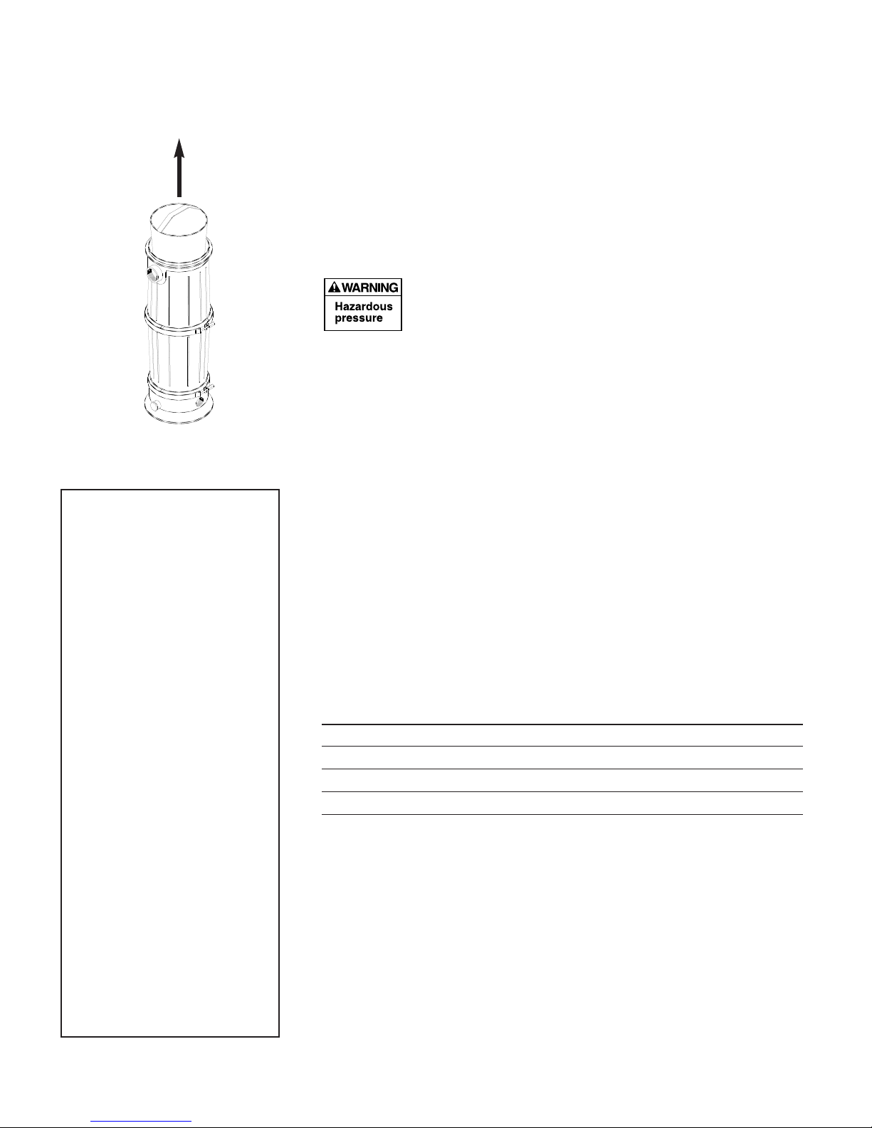
1. Thoroughly clean separation tank bag as follows:
A.Remove bag (see Figure 5) and dump spent DE into waste container.
NOTICE: Do not expose bag to direct sun for long periods. Direct sun will
cause the cloth to deteriorate.
B. Hose down bag and replace in separation tank.
C. Replace with a new bag if necessary.
2. Inspect "V" Band clamps.
Iffaulty “V” band clamp is used, clamp may fail, causing tank
to blow up. This can cause severe injury or major property
damage. See side-bar (at left) for clamp inspection instructions.
3. Clean air release valve of accumulated dirt, hair, etc.
Reassembly/Closing Tank:
1. Clean “O” Ring and sealing area of tank body. Check "O" Ring for damage.
If it is damaged, replace it. If it is OK, lubricate with approved lubricant
(see chart) and place in seat.
NOTICE: Top and middle clamps and “O” Rings are not interchangeable
with bottom clamp and “O” Ring; DO NOT mix them up.
2. Do not remove or damage safety and instruction labels during cleaning.
Replace any decals which may have been damaged.
3. Install clamp and knob assembly; tighten knob securely hand tight. To assist
sealing, tap clamp around tank with mallet while tightening knob. Gap
between ends of clamp should be 1/4" to 3/8" when clamp is tight and
properly seated (see side-bar at left). If not, consult your pool professional.
4. Replace plugs or close valves in Tank Drain and Auxiliary Drain ports.
NOTICE: Leave Air Release Valve OPEN and return line By-Pass Valve
CLOSED. Separation Tank should not be under pressure during normal
filter operation.
6. Consult Filter Owner’s Manual for filter startup procedure.
STA-RITE APPROVED O-RING LUBRICANTS
Petroleum Jelly (Vaseline®) Semi-Permanent Lubrication
Parker Super-O-Lube™ Semi-Permanent Lubrication
Aqua-Lube®by Allube Semi-Permanent Lubrication
5% or less Mild Soap Solution Assembly Lubrication
Figure 5: Lift basket to
remove.
Clamp Inspection
1. Check for broken or cracked welds.
2. Check threads for galling, dirt, ex-
cessive wear.
3. Check knob/nut for cracks, break-
age, thread wear, thread galling, etc.
4. Check tank sealing surfaces and
clamp inner surface for dirt or corro-
sion. Clean where necessary.
5. Replace any parts showing damage
or visible wear and tear.
Clamp Tightening
1. Normal tightening will cause
threads to squeak; do not use the
squeak as an indication of tightness.
2. Tap clamp with a mallet while tight-
ening to aid clamp seating.
3. Tighten until clamp ends are be-
tween 1/4" and 3/8" apart.
4. If tank leaks after tightening clamp,
proceed as follows:
A. Stop pump; release all pressure.
B. Remove clamp; clean clamp,
O-Ring, and tank flanges.
C. Follow instructions under
"Reassembly/Closing Tank"(at
right) to reassemble tank.
D. If leak persists, consult your
pool professional.
5. In normal use, middle and bottom
clamps should not need removal.

8
SEPARATION TANK
INSPECTION
Weekly Inspection: Skimmer basket - remove debris. For systems with
bypass valve, make sure separation tank is not under pressure.
Bi-Yearly Inspection: Check separation tank/return line bypass valve for
proper sealing as follows: With filter valve in `FILTER’ position and separation
tank cover off, start pump. No water should enter separation tank from lower
port. If water does enter, stop pump and inspect bypass valve for leaks and
debris. Clean or replace as necessary.
WINTERIZING
1. Open air release valve; open all system valves. Position multiport valve
between port positions to allow air passage to all ports.
2. Remove all drain plugs from trap, pump, valve, filter, and separation tank.
3. Drain all piping and cover system with plastic or tarpaulin to keep it dry.

1
2
20
4
19
5, 6, 7
8
9
18
5, 7
15
8
4
17
16
15 11,7
12
13
10
14
3
9
REPAIR PARTS
Key Part No. Part
No. Description Used No.
1 Air release valve Assembly 1 25010-0200
2 O-Ring 1 *
3Lid Assembly
(Incl. #1, #20, & Decals) 1 25005-9001
4 O-Ring 2 31935-0001
5Decal “Top Clamp” 2 WC27-46
6 Decal “Pressure Warning” 1 WC27-23
7 Decal “Clamp Warning” 3 WC27-19
8 “V” Clamp 2 25010-9101
9 Separation bag 1 25005-0015
10 Separation tank liner 1 25005-0016
11 “V” Clamp 1 25010-9100
12 1-1/2" PVC plug 1 36205-4008T
13 Base assembly 1 WC104-78PB
14 Decal “Thread Seal Warning” 1 WC27-27
15 Clamp nut 2 WC36-1
16 O-Ring 1 WC9-3
17 Lower body 1 25010-0001
18 Upper body 1 25005-0001
19 Clamp knob 1 WC36-22
20 1/4" NPT Plug 1 WC78-40T
• Model Decal 1 32155-4050
•Warning Decal 1 32155-4049
• Operating Instruction Decal 1 32155-4051
•Not Illustrated.
*Standard hardware item; purchase locally.

10
This page is blank.

This page is blank.

S303 (Rev. A 4/16/09)
© 2009 Pentair Water Pool and Spa, Inc. All rights reserved.
This document is subject to change without notice.
1620 Hawkins Ave., Sanford, NC 27330 • (800) 831-7133 • (919) 566-8000
10951 West Los Angeles Ave., Moorpark, CA 93021 • (800) 831-7133 • (805) 553-5000
Trademarks and Disclaimers: Sta-Rite®is a trademars and/or registered trademars of Pentair Water Pool and Spa, Inc. and/or its affiliated companies in the United
States and/or other counties. Plasto-Joint Stik®is a registered trademark of La-Co Industries, Inc., Teflon®is a registered trademark of E.I. Du Pont De Nemours and
Company Corporation, Silastic 732®is a registered trademark of Dow Corning Corporation, Vaseline®is a registered trademark of Unilever Supply Chain, Inc.,
Parker Super O-Lube™ is a trademark of Parker Hannifin Corp., Aqua-Lube®is a registered trademark of Tifco Industries, Inc. Unless noted, names and brands of others
that may be used in this document are not used to indicate an affiliation or endorsement between the proprietors of these names and brands and Pentair Water Pool and
Spa, Inc. Those names and brands may be the trademarks or registered trademarks of those parties or others.
Table of contents
Popular Water Heater manuals by other brands

Toyotomi
Toyotomi Oil Miser OM-180 installation manual

clage
clage E-convenience DSX Touch quick guide

State Water Heaters
State Water Heaters SRGSS01806 Specifications

gledhill
gledhill Xstream installation instructions

Livington
Livington Instant water heater User instructions

Heatworks
Heatworks MODEL 3 User manual & installation guide

Philips
Philips AWH1130 user manual

Bosch
Bosch 125B LP Installation & operating instructions

Main
Main Mersey Super User, installation & servicing instructions

Regulus
Regulus PS2F N+ Series Installation and operation manual

PVI Industries
PVI Industries 50 L 130 A-GCML Installation & maintenance manual

Philips
Philips AWH1620/51(30YC) user manual