Stack ST8100 User manual

51
Users Guide
ST8100 Display System
Users Guide
PART NO. ST54030-007

50 Users Guide
i
Users Guide
STACK ST8100 Display System Preface
Congratulations
Congratulations on choosing the Stack ST8100 Display
System. This system will give you a wealth of information
to enable you to obtain the maximum safe performance
from your vehicle.
Registration Form
Please complete and return the registration form contained
in the package. This will allow us to keep you up to date
on the latest developments from Stack.
Purpose of this manual
Please complete and return the registration form contained
in the package. This will allow us to keep you up to date
on the latest developments from Stack.
Edition Notice
This edition is for all versions of the ST8100 Display System
distributed to customers worldwide. The units of
measurement used to illustrate the use of the Display
System in this edition are for the UK version.
Preface
Parameter Type UK Version US Version EC Version
Speed MPH MPH km/h*
Temperature Degrees C Degrees F Degrees C
Wheel Circumference Millimetres Inches Millimetres
Pressure PSI PSI Bar

ii Users Guide
STACK ST8100 Display SystemPreface
49
Users Guide
United Kingdom Telephone Numbers:
Sales: 01869 240404
Tech Support: 01869 240420
Fax: 01869 245500
Email: [email protected]
Web site: www.stackltd.com
United States Telephone Numbers:
Sales: 888-867-5183
Fax: 888-364-2609
Email: [email protected]
Web site: www.stackinc.com
If you need information about other Stack motor sport
products, these can be obtained from Stack or from your
local Stack dealer. Products available from Stack include:
• Intelligent Tachometers
• Boost Gauges
• Analogue Sensors
• Digital Sensors
• Data Logging Systems
• Display and Logging Systems
• Radio Telemetry Systems
• Display and Analysis Software
• Video Overlay Systems
Stack and its approved distributors provide a
comprehensive Technical Help service to assist with your
enquiries. Contact your local Stack branch or distributor.
For a current list of distributors log onto the Stack websites
and click on the WHERE TO BUY TAB at the top of the
home page.
For online technical support click on the Support
tab at the top of the home page. Fill in the support
form mandatory elds to gain access to a list of PDF
manuals that can be viewed or downloaded.
Related Products From Stack Limited
Who to Contact at Stack in Case of Difculty

48 Users Guide
Index STACK ST8100 Display System
iii
Users Guide
STACK ST8100 Display System Preface
PREFACE............................................................................................. i
Related Products From Stack Limited. .............................................ii
Who to Contact at Stack in Case of Difculty.................................. ii
CONTENTS....................................................................................... iii
Chapter 1. Introducing the Display System..................................... 1
How to Use this Manual .................................................................. 2
Chapter 2. Getting Started................................................................ 3
The Display Module ........................................................................ 4
Wiring Harness ................................................................................ 4
Connecting the Components............................................................ 5
Chapter 3. Operating the Display System ....................................... 6
Switching the Display System on .................................................... 6
Changing the display layers............................................................. 6
Peak Values (Tell Tales .................................................................. 10
Alarms............................................................................................ 12
Lap times........................................................................................ 14
Gear shift light ............................................................................... 15
Lap Time Memory (optional.......................................................... 15
Chapter 4. Conguring the Display System .................................. 16
System Conguration Mode .......................................................... 16
Leaving conguration mode .......................................................... 20
Chapter 5. Installing the Display System....................................... 21
Who can install the Display System .............................................. 21
Tools needed to install the Display System ................................... 21
Precongured Display Systems ..................................................... 21
Custom Congured Display Systems ............................................ 21
Fitting the Display Module ............................................................ 22
Switches ......................................................................................... 23
Warning lights................................................................................ 24
Engine Speed (RPM) Measurement............................................... 24
Connecting the Display System to the Ignition System................. 24
Pressure sensors ............................................................................. 25
Temperature sensors....................................................................... 27
Wheel speed sensor (optional ........................................................ 28
Lap timing sensor (optional ........................................................... 29
Contents Index
additional external warning lights, 24
alarm for battery voltage, 12
alarm for fuel pressure, 12
alarm for oil pressure, 12
alarm for oil temperature, 12
alarm for Water Temperature, 12
alarm warning light, wiring label, 4
alarms, 12
alarms, switching on or off, 20
analogue tachometer, 4
battery voltage, 7
battery voltage alarm, 12
checks and alarms, 34
clearing an alarm, 13
conguring the display system, 16
Corner Speed option, 3
current speed, 7
custom congured ST8100, 21
data logging subsystem, wiring label, 4
digital display panel, 4
Display Layer 1, 7
Display Layer 2, 7
display layer 3, 8
Display Layer 4, 8
display layer 5, 9
display layers, 6
display module, 4
Display System, template, 43
engine speed (RPM), 24
engine speed (RPM), wiring label, 5
external warning lights, additional, 24
fastest lap time, 8
tting the display module, 22
fuel pressure, 7
fuel pressure alarm, 12
fuel pressure sensor, wiring label, 5
gate value, 10, 12
gear shift light, 15
gear shift warning light, 2
gear shift warning light, wiring label, 4
Installing the Stack ST8100, 21
labels on wiring, 4
lap number, 8
lap time, 8
Lap Time Memory option, 3
lap times, 14
lap timing sensor, 29
lap timing switch, wiring label, 4
lateral G-force sensor, 32
lateral G-force sensor, wiring label, 5
maximum water temperature alarm, 17, 18
oil pressure, 7
oil pressure alarm, 12
oil pressure sensor, wiring label, 5
oil temperature, 7
oil temperature alarm, 12
oil temperature sensor, wiring label, 5
operating of the system, 6
optional components, 3
peak value memory, 11
peak values, 1
peak values (tell tales), 10
peak values, resetting, 11
performance parameters, 1
power supply, 5
power supply to trackside beacon, 31
Predictive Lap Timer option, 3
pressure sensors, 26
resetting the peak values, 11
RPM gate value, 10, 12
showing the last alarm, 13
Stack distributors, ii
standard components, 3
Standard contact breaker system, 25
switch functions, summary of, 47
switches, 23
switching the system on, 6
tachometer, 4
temperature sensors, 27
Template for the Display Module, 43
tools needed, 21
trackside infra-red lap beacon, 30
unpacking, 3
warning lights, 24
warning messages, 1
water temperature, 7
water temperature alarm, 12
water temperature sensor, wiring label, 5
wheel speed sensor, 28
wheel speed sensor, wiring label, 4
wires in the harness, labels, 4
Wiring Harness, 4
Wiring Harness Schematic Diagram, 45
wiring harness, installation of, 33

iv Users Guide
STACK ST8100 Display SystemPreface
47
Users Guide
Appendix D. Summary of Switch FunctionsSTACK ST8100 Display System
Functions Switch or Switches
Show Peak Values Switch 1
Change Display Layer Switch 3
Clear Alarm Switch 2 or Switch 3
Show Last Alarm or
Enter Lap Time Memory (optional)
Switch 2
Manual Lap Marker Switch 4
Latch Corner Speed Display Switch 1
Reset Peak Values Switches 1 & 3 together
Reset lap count and lap time to zero Switches 1 & 4 together
Enter System Conguration Mode Switches 1 & 2 together
Functions Switch or Switches
Decrease the value of the parameter being displayed Switch 1
Increase the value of the parameter being displayed Switch 2
Enable or disable an alarm for the parameter being
displayed
Switchs 1 & 2 together
Display the next congurable parameter Switch 3
Quit conguration mode and return to normal mode Switch 4
Functions Switch or Switches
Show Previous Lap Time Switch 1
Show Next Lap Time Switch 2
Quit Lap Time Memory Switchs 3
Appendix D. Summary of Switch Functions
Normal Operation
System Conguration Mode
Lap Time Memory Mode (optional)
The Stack ST8100 Display System monitors and displays
a range of values, known as performance parameters,
needed for effective car and driver management in most
competitive situations.
The system combines an analogue tachometer with a
digital display for the following performance parameters:
• Wheel speed (optional)
• Lap times up to 45 minutes
• Lap Time Memory (optional)
• Engine speed (RPM)
• Oil pressure
• Oil temperature
• Water temperature
• Fuel pressure
• Battery voltage
• Fuel pressure
• Battery voltage
• Lateral acceleration (optional). This option is used only in
conjunction with the optional logging system. The information from
it is not displayed on the Display Module.
• Predictive Lap Timer display (optional)
• Maximum and Minimum Corner Speeds display(optional)
You can view the peak values (tell-tales) for all the parameters.
The system provides a range of warning messages based on
preset alarm values for the following performance parameters:
• Oil pressure
• Oil temperature
• Water temperature
You can enable or disable the warning system for each
parameter individually.
You can redene the preset alarm value for each parameter to a
value that is more suitable for your vehicle.
The system provides a gearshift warning light that illuminates
above a RPM value that you dene for your vehicle.

46 Users Guide
1
Users Guide
STACK ST8100 Display System Chapter 1. Introducing the Display System
Chapter 1. Introducing the Display
System
Returned Goods Form
The Stack ST8100 Display System monitors and displays
a range of values, known as performance parameters,
needed for effective car and driver management in most
competitive situations.
The system combines an analogue tachometer with a
digital display for the following performance parameters:
• Wheel speed (optional)
• Lap times up to 45 minutes
• Lap Time Memory (optional)
• Engine speed (RPM)
• Oil pressure
• Oil temperature
• Water temperature
• Fuel pressure
• Battery voltage
• Fuel pressure
• Battery voltage
• Lateral acceleration (optional). This option is used only in
conjunction with the optional logging system. The information from
it is not displayed on the Display Module.
• Predictive Lap Timer display (optional)
• Maximum and Minimum Corner Speeds display(optional)
You can view the peak values (tell-tales) for all the parameters.
The system provides a range of warning messages based on
preset alarm values for the following performance parameters:
• Oil pressure
• Oil temperature
• Water temperature
You can enable or disable the warning system for each
parameter individually.
You can redene the preset alarm value for each parameter to a
value that is more suitable for your vehicle.
The system provides a gearshift warning light that illuminates
above a RPM value that you dene for your vehicle.
In the unlikely event of a Stack part developing a fault and requiring repairs,
you are kindly requested to send the part back to Stack Ltd with a
completed Returned Goods Form. Returning a part without this form will
lengthen the repair time and possibly increase the cost of the repair.

2Users Guide
STACK ST8100 Display SystemChapter 1. Introducing the Display System
45
Users Guide
STACK ST8100 Display System Appendix B. Wiring Harness Schematic Diagram
How to use this Manual
Appendix B. Wiring Harenss Schematic
Diagram Stack recommends that you unpack and connect the
components in the system before you install it in your
vehicle. This will enable you to familiarise yourself with
operating the display and conguring it for the vehicle in
which you intend to install it.
This manual starts by taking you through the process of
setting up the system before installation, operating the digital
display, conguring the system and setting the alarm values
and installing it in the vehicle. By the end of Chapter 2 you
will have set up the system so that you will be assured that it is
functioning normally. You can then read Chapter 3 and
practice using its functions. Chapter 4 takes you through
conguring it for your vehicle, Chapter 5 explains how to
install it in the vehicle and Chapter 6 provides a set of troubleshooting
guidelines.
A template for the Display Module dashboard cut-out is
provided in Appendix A and a schematic diagram of the
wiring harness is in Appendix B.
Please note that this manual does not attempt to explain how
to interpret or use the information from the ST8100 Display
System as this is very specic to the type of vehicle in which
it is installed and the type of competition in which the vehicle
is engaged.

3
Users Guide
STACK ST8100 Display System Chapter 2. Getting Started
Standard ST8100 Display System Items
Optional ST8100 Display System Items
Chapter 2. Getting Started
This chapter guides you through the initial unpacking
and setting-up of the equipment for pre-installation checks and
familiarisation with its operation.
The ST8100 Display System is supplied with the following
standard components.
The ST8100 Display System can be used with the following
optional components.
Quantity Description
1 RPM Sensor (ST696 Opto Isolator or ST697 H.T. Pick-
up)
1 Wheel Speed Sensor (ST670)
1 Lateral G-force Sensor (ST791)
1 Infra-red Lap Time Receiver (ST543)
1 Infra-red Lap Time Beacon (ST544)
1 External Gear Shift Warning Lamp (ST534, ST537)
1 External Alarm Warning Lamp (ST533, ST536)
1 “Max” Option This includes the Predictive Lap Timer,
Corner Speed and Lap Time Memory displays pre-tted
in the Display Module.
Quantity Description
1 Display Module (ST867) with 2 mounting brackets
1 Wiring Harness (ST872-006)
2 Pressure Sensors (ST747 + thread adapters)
2 Temperature Sensors (ST760, ST761, ST762 or ST764)
4 Switches (ST514)

4Users Guide
STACK ST8100 Display SystemChapter 2. Getting Started
43
Users Guide
STACK ST8100 Display System Appendix A. Template for the Display Module
The Display Module
Appendix A. Template for the Display Module
Wiring Harness
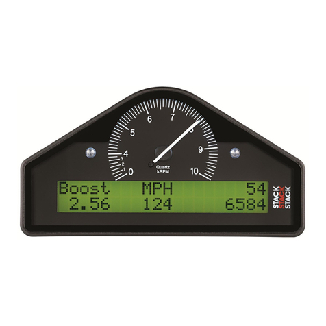
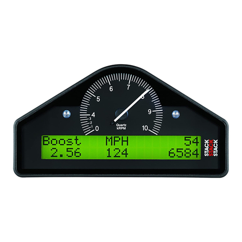
The Display Module consists of an analogue tachometer and a
digital display panel.
Use the template on the following page for cutting out an
aperture for the Display System.
The Display Module is connected to a variety of sensors by a
wiring harness. The wiring harness has a 19-way military
connector for connection to the Display Module.
Labels on short cables Connection To
REG 5 volt regulator stub
S1 to S4 Switches 1 to 4
WS Wheel speed sensor
LAP Lap timing sensor
SL Gear shift warning light
AL Alarm warning light
NET Data logging expansion pack
ECU
(Not normally tted)
Allows specially congured systems to
communicate with engine control units
Each of the wires in the harness is labelled.

425
Users Guide Users Guide
STACK ST8100 Display SystemSTACK ST8100 Display System Chapter 2. Getting Started Chapter 2. Getting Started
Connecting the Components
Labels on Long Cables: Connection To
ES Engine Speed (RPM)
OT Oil temperature sensor
WT Water temperature sensor
OP Oil pressure sensor
F Fuel pressure sensor
A Accelerometer sensor
B+ Battery Positive
B- Battery Negative (Earth)
1. Connect the wiring harness to the Display Module.
2. Connect the four switches to the cables labelled S1 to S4.
3. Connect each of the sensors that you have purchased to
the appropriate wire in the wiring harness, as shown
above.
4. Connect a 12v DC power supply to the power input cable.
5. Switch on the 12v DC power supply.
The Display Module should start up with an alarm signal
indicating low oil pressure.
This is normal in this environment.
You can now proceed to familiarise yourself with operating
the Display Module.
Symptom Possible Cause Remedy Notes
Display and
alarm light
ash when
engine is
running
Intermittent
alarm caused by
a parameter with
its alarm level
set too close
to the normal
operating
Either change
the value for the
alarm off
Press switch 2 to see
which sensor is causing
the alarm
Display works
ok until the
engine starts
the Display
freezes
or resets
continuously
Intererence from
Ignition system
& HT Leads
Fit Suppressed
(Silicon) HT Leads
Fit a suppression
capacitor (2.2uF)
between the
coil (battery
connection) &
chassis
Use'Helica!' suppressed
leads in extreme cases
ST8100 wiring
close to HT leads
& or injector
leads, or HT
leads tied to
isolated metal
work to which
ST8100 wiring is
also tied.
Run /st8100
wiring away
from HT leads &
injector leads.
Recommended
Minimum spacing
75mm (3.0")

6Users Guide
STACK ST8100 Display SystemChapter 3. Operating the Display System
41
Users Guide
STACK ST8100 Display System Chapter 2. Getting Started
Switching the Display System on
Changing the display layers
Chapter 3. Operating the Display System
This chapter takes you through the operation of the system so
that you can familiarise yourself with its use before you install
it in the vehicle.
Switching the Display System on
You will have switched the system on already if you have
followed the instructions in the previous chapter and have just
set the system up for the rst time before installing it.
When installed in the vehicle, the system is switched on when
you switch the ignition on.
When the power is rst switched on, the digital display will
immediately show a "Low Oil P" warning and the alarm light
will come on. The tachometer will reset itself by moving the
needle until it touches the stop-pin and then moving it back
to the zero RPM position. Press Switch 2 or Switch 3 to clear
the warning message from the display.
The digital display panel and the analogue dial face are always
backlit when the system is switched on.
If none of these actions occurs when you switch on, switch off
the power to the system and consult the section on
troubleshooting in this manual.
The digital display can show separate sets of parameters and
their values on the various display layers.
Each of the display layers can be displayed in turn by pressing
Switch 3. Press Switch 3 when the last display layer is being
displayed in order to return to the rst display layer. The
Display System will remember which display layer was
showing when the unit was switched off and will redisplay
that layer at power-up.
The format of the values in these displays will vary for systems
supplied outside the UK because the parameters are displayed
in different units.
Symptom Possible Cause Remedy Notes
Display values
and messages
unclear or
unreadable
(poor contrast)
Display too hot
or too cold
Ensure that
the display is
operated within
the specied
temperature range
System
congured with
wrong wheel
circumference
Typical wheel
circumference for a
car is 1800mm / 70° or
900mm / 35° for a kart
No speed
reading. Speed
reading erratic,
value jumps
high or low
Faulty sensor
and/or wiring
Check sensor
indicator for
correct operation
Rotate the wheel by
hand and check that
the sensor indicator
lights up as each target
passes the sensor
Incorrect sensor
gap (too far
apart or too
close)
Check that the gap
is approximately
1mm
Sensor and
targets moving
apart
Fabricate a more
rigid sensor
bracket
No alarm
for water,
oil, or fuel
(temperatures
and pressures)
being
displayed
All the alarms
have been
switched off
Switch on the
required alarms
Alarms only operate
when the engine is
running at the RPM
gate value or above it
The engine RPM
gate value is set
too high
Reset the RPM
gate to a lower
value

40 Users Guide
STACK ST8100 Display SystemChapter 2. Getting Started
7
Users Guide
STACK ST8100 Display System Chapter 3. Operating the Display System
Display Layer 1
Display Layer 2
Display layer 1 shows:
• Water Temperature (WATER)
• Oil temperature (OIL T)
• Current speed (SPEED).
• Oil Pressure (OILP)
Press Switch 3 to see display layer 2.
Display layer 2 shows:
• Battery voltage (BATT)
• Oil Temperature (OIL T)
• Fuel Pressure (FUELP)
• Oil Pressure (OILP)
Press Switch 3 to change display to layer 3
Symptom Possible Cause Remedy Notes
Display values
and messages
unclear or
unreadable
(poor contrast)
Display too hot
or too cold
Ensure that
the display is
operated within
the specied
temperature range
Operating temperature
is -20°C (+5°) to 70° C
(+160°F)
ECU interface
shorted. Not
normally tted
Check the two core
screen ECU wires
for short circuits
ECU wire is 300mm
inside the main sensor
leads sleeve. Make sure
that none of the wire
ends are shorted
No RPM speed
reading
Incorrect wiring Check the
connection of the
engine speed wire
to the ignition
system (or sensor,
if used)
See instructions
supplied in the manual.
If connected directly to
the coil, check that it
is to the switched low
tension side (usually
the negative side)
Displayed
RPM value too
high or to low
by a constant
%-age amount
System
congured with
wrong number
of engine
cylinders.
Recongure system
to correct number
of cylinders.
Ignitions System may
either: a) produce
"waste" sparks giving
double the number
of cylinders per
revolution
Ignition system
pulses per
revolution not
same as number
of cylinders
Recongure
system to correct
number of pulses
per revolution.
Tachometer
reading erratic
pointer jumps
high or low
Incorrect wiring Reconnect the
tachometer as
specied in this
manual
Signal from
ignition system
or coil is noisy
Condition the ES
signal by placing a
resistor in line with
the ES wire
Resistor values (1/2W)
5% 350v) 10K ohms for
dedicated tacho output
47K ohms for coil
connection (non CDI)
100K ohms for CDI
connection.

8Users Guide
STACK ST8100 Display SystemChapter 3. Operating the Display System
39
Users Guide
STACK ST8100 Display System Chapter 6. Troubleshooting
Display Layer 3
Display Layer 4
Display layer 3 shows:
• Lap number of the last completed lap
• Lap time for the last completed lap
• Lap number of the fastest lap
• Fastest lap time (BEST)
Press Switch 3 to display layer 4.
Display layer 4 shows:
• Fastest lap time
• Running time from the start of the current lap
The following two features are only active if the Predictive Lap
Timer has been purchased:
• Predicted time for the current lap based on the difference in time
taken to reach the same position on the fastest lap.
• A graphical comparison of this lap to the fastest lap. ‘+’
means the vehicle is going faster than the fastest lap and ‘–‘
means it is going slower.
Press Switch 3 to change the display either back to layer 1 or
on to layer 5 if you have the Corner Speed option
Symptom Possible Cause Remedy Notes
Switch 4: does
not set or
display pop-up
lap times when
no automatic
receiver in use
Switch 4 faulty Replace switch Disconnect the switch
and short the leads
together.
If display changes,
replace switch 4.
Otherwise check
wiring.
Faulty switch
wiring
Check switch
wiring for correct
continuity
Pin U to yellow S4 wire
less than 1.0 Ohm and
Pin Uto Pin H (earth)
greater than 1M Ohms
Lap time is
not displayed
automatically
(automatic
receiver is
tted)
Lap marker
receiver faulty
Check lap marker
wiring
Disconnect receiver
and press lap switch
4. If didplay changes
replace receiver after
checking wiring.
Lap marker
receiver fauly
Replace lap marker
receiver
External
warning light
is dead when
the display
warning light
is OK
Bulb has burnt
out
Replace bulb Swap with the other
light to conrm burnt
out bulb. If not burnt
out check wiring.
Faulty wiring to
light
Check continuity
of wiring
Pin G to red AL wire
less than 1.0 Ohm and
Pin N to yellow AL
wire greater than 1.0
Ohm
External gear
shift light dead
Bulb has burnt
out
Replace bulb wap with the other
light to conrm burnt
out bulb. If not burnt
out check wiring.
Faulty wiring to
light
Check continuity
of wiring
Pin G red SL wire less
than 1.0 Ohm and Pin
M to green SL wire
greater than 1.0 Ohm

38 Users Guide
STACK ST8100 Display SystemChapter 6. Troubleshooting
9
Users Guide
STACK ST8100 Display System Chapter 3. Operating the Display System
Display Layer 5 (optional)
Display layer 5 shows:
• Current speed (SPEED)
• Speed at the moment when Switch 1 was last pressed
(HOLD)
• Highest speed attained on the previous straight (MAX)
• Lowest speed attained in the previous corner (MIN)
Press Switch 3 to display layer 1 again
Symptom Possible Cause Remedy Notes
Peak values
not updated
Gate value set
too high
Change Gate RPM
in the display
conguration
menu
Peak values only
updated while the
engine RPM is greater
than the Gate value
Internal
memory battery
is dead
Return unit to
Stack for new
battery service
Display shows "!! MEM
BATT !!" warinig on
power up
Switch 1: Show
peak values
does not work
Switch 1 faulty Replace switch Disconnect switch
and short its leads.
If display changes,
replace switch 1
Otherwise check
wiring.
Faulty switch
wiring
Check switch
wiring for correct
continuity
Pin K to res S1 wire
less than 1.0 Ohm and
Pin K to Pin H (earth)
greater than 1 M Ohms
Switch 2 Show
last alarm
function does
not work
Switch 2 faulty Replace switch Disconnect switch
and short its leads.
If display changes ,
replace. Otherwise
check wiring.
Faulty switch
wiring
Check switch
wiring for correct
continuity
Pin L to Red S2 wire
less than 1.0 Ohm and
Pin L to Pin H (earth)
greater than 1M Ohims
Switch 3
Charge display
layer function
does not work
Switch 3 faulty Replace switch If display changes ,
replace. Otherwise
check wiring.
Faullty switch
wiring
Check switch
wiring for correct
continuity

10 Users Guide
STACK ST8100 Display SystemChapter 3. Operating the Display System
37
Users Guide
STACK ST8100 Display System Chapter 6. Troubleshooting
The system can display the peak values (sometimes called
(‘tell-tales’) that have been recorded during a run for all the
monitored parameters.
Peak values are updated only when the engine speed has
exceeded its ‘gate value’ for RPM for at least one second. This
allows the values to stabilise. Blipping the engine may not
be enough to update the peak values. The gate value is
a predened RPM value that is used to control when the
system updates the peak values. This is to prevent abnormal
peak values from being recorded when, for example, the
engine is either not running, is idling or is being warmed up.
The system stores either a maximum or a minimum value as
the peak value, depending on the parameter, as follows:
Press and hold Switch 1 to show the peak values for the
parameters currently being displayed. Release the switch to
return to the normal display.
Parameter Type of Peak Value Gated to RPM
Engine Speed (RPM) Maximum Yes
Oil Temperature Maximum Yes
Water Temperature Maximum Yes
Oil Pressure Minimum Yes
Fuel Pressure Minimum Yes
Battery Voltage Minimum Ye s
Wheel Speed Maximum Yes
Peak Values (Tell Tales)
Displaying the Peak Values
Symptom Possible Cause Remedy Notes
Fixed pressure
reading of 999.9
PSI or 99.99 Bar
Pressure sensor
has failed
Replace sensor
Faulty sensor
connections
Check continuity
of sensor leads for
open circuit
Pin D to the red OP
wire, pin R to the red
F wire and pin H to
both the black OP
and F sensor wire
Fixed pressure
reading of -99.9
PSI or -9.99 Bar
Pressure sensor
has failed
Replace sensor Disconnect sensor. If
reading changes to
999, replace sensor.
Faulty sensor
connections
Check continuity
of sensor leads for
short circuits
Check the wiring
harness for short
circuit
Fixed pressure
reading of 0.0
PSI or 0.00 Bar
or suspected
low/slow
reading
Pressure sensor
has failed
Replace sensor Swap with the other
pressure sensor to
conrm fault.
Faulty sensor
connections
Check pressure
connections
Check plumbing for
blockage. (kinks in
exible hoses)
All sensors
show xed high
values
Switch 1 (peaks)
faulty
Replace switch Disconnect switch.
If normal values
return, replace
switch.
Faulty switch
wiring
Check switch
wiring
Check wiring for
short between
connector pins K
and H (earth)
Displays
pressure values
too low and
temperature
values too high
Low Battery
voltage
Recharge battery The system does
not give accurate
readings when
voltage is below
9.0V
Sensor reading
incorrect
Another gauge
connecter to
sensor
Disconnect other
gauge
It is not permissible
to connect a second
gauge

36 Users Guide
STACK ST8100 Display SystemChapter 6. Troubleshooting
11
Users Guide
STACK ST8100 Display System Chapter 3. Operating the Display System
You can reset all of the peak values, except the fastest lap time,
manually. All peak values are reset at the same time. If the
engine is running at or above its gate value when the peak
values are reset, they are set to the current value of each
performance parameter.
To reset the peak values:
• Press and hold Switch 1 to display the peak values.
• While holding Switch 1, press and hold Switch 3.
• With Switch 3 held down, you will see the display revert
to the current values. The new peak values that are stored
are those being displayed when you release Switch 3.
If the engine is running below its gate value, the peak values
are not reset to the current values but are set to the following
values:
The peak values are stored in a memory that is powered by
an internal back-up battery. They remain stored in this
memory when the external power source is disconnected from
the system. The system needs to be returned to Stack every
4-5 years for the internal battery to be changed. An alarm is
triggered when the power from this battery drops below a safe
level and the warning "MEM BATT" is displayed.
Parameter New Peak Value
Engine RPM 0 RPM
Wheel speed 0 MPH or 0 km/h
Oil Pressure 999.9 PSI or 99.99 bar
Fuel Pressure 99.99 PSI or 99.99 bar
Oil Temperature 0°C or 0°F
Water Temperature 0°C or 0°F
Battery Voltage 26.0V
Peak Value Memory
Resetting the Peak Values
Symptom Possible
Cause
Remedy Notes
The !! LOW OIL !!
message does NOT
appear on power up.
The warning light is
not turned on.
Pressure
sensor has
failed
Replace sensor Swap with the fuel
pressure sensor to
conrm fault
Sensor
connections
are faulty
Check for
continuity on
sensor lead.
A reading of 999 on
the display indicates
an open circuit
connections (pin D
to the red sensor
lead and pin H to
the black sensor
lead)
Oil pressure
alarm
disabled
Check that the
oil pressure
alarm is set on.
Display gives a xed
temperature reading of
999 C or 999 F
Temperature
sensor has
failed
Replace sensor Disconnect sensor.
If reading changes
o 0, replace sensor.
Otherwise check
harness for short
circuit.
Faulty sensor
connections
Check
continuity of
sensor leads
Display gives a xed
temperature reading 0°
C or 0° F when engine
temperature is above
12° C or 55° F
A temperature
sensor has
failed
Replace sensor Disconnect sensor
and short its leads
together. If the
reading changes
replace the sensor.
Faulty sensor
connections
Check
continuity of
sensor leads
for open
circuits
Check the wiring
harness for open
circuits (pin E to the
red OT sensor wire
pin P to the WT wire
and pin H to both
the black OT and
WT sensor wires)

12 Users Guide
STACK ST8100 Display SystemChapter 3. Operating the Display System
35
Users Guide
STACK ST8100 Display System Chapter 6. Troubleshooting
Symptom Possible Cause Remedy Notes
Display is dead
(no backlight,
nothing on
display, no green
dial lights)
Ignition is off Turn ignition on The power
lead is
labelled B+
& B-
The battery
positive lead
B+ is 19w
conn pin G.
B- is 19w
connector pin
H.
Battery is dead Recharge or replace
battery
Power connection
to B+ or B- is
faulty
Check if battery is
connected correctly.
Check power lead
continuity
Display is dead
(no backlight,
nothing on
display, green
dial lights on
but dim)
or
!! LOW BATT
!! warning on
display
Battery is almost
dead
Recharge or replace
battery
Power connection
to B- or B+ is
faulty.
Check power lead
continuity.
Display ashes
and dial pointer
resets or
vibrates
Battery is almost
dead
Recharge or replace
battery
Power connection
to B- or B+ is
faulty
Check power lead
continuity
The Display System has built-in warnings to alert the driver
when certain parameters either exceed or fall below their
alarm values. For example, a warning is signalled if the fuel
pressure falls below its alarm value or if the oil temperature
rises above its alarm value. You can adjust the preset alarm
levels when you congure the Display System. See Chapter 4,
Conguring the Display System in this manual.
Some of the warnings (see the following table) are triggered
only while the engine speed exceeds its "gate value" for RPM
for at least one second. Blipping the engine should not be
enough to trigger a warning. The gate value is a predened
RPM value that is used to control when the system is to
trigger a warning. This is to prevent abnormal warnings from
being triggered when, for example, the engine is either not
running, is idling or is being warmed up.
(The oil pressure alarm will come on at power-up until the
engine is started and the pressure exceeds the threshold set for
its alarm.)
The Display System has the following built-in alarms:
Parameter Alarm is triggered when
the:
Gated to RPM
Oil Temperature current value exceeds the
preset value
Yes
Water Temperature current value exceeds the
preset value
Yes
Oil Pressure current value drops below
the preset value
No
Fuel Pressure current value drops below
the preset value
Yes
Battery Voltage current value drops below
the preset value
No
Alarms
Chapter 6. Troubleshooting

34 Users Guide
STACK ST8100 Display SystemChapter 5. Installing the Display System
13
Users Guide
STACK ST8100 Display System Chapter 3. Operating the Display System
When an alarm condition occurs, the built-in amber warning
light turns on and the digital display gives a warning message
to show the type and value of the alarm.
If you purchased the optional External Alarm Warning Lamp,
that lamp will illuminate at the same time.
(6 inches) of heatshrink
sleeving to provide additional strain relief for the cable
where it enters the 19-way connector.
• Connect the wires when all the sensors are in position and
you have secured the wiring harness.
See Chapter 2 if you need to check the labels used to identify
the individual cables in the wiring harness.
You should check the system to ensure that all the sensors are
detecting the correct values. You should also run the engine
up to its operational levels to check that the values displayed
by the Display System are accurate. You should then check out
the alarm systems to ensure that they are functioning correctly
before going out on to the circuit.
Press Switch 2 or Switch 3 while the alarm is being displayed.
Press and hold Switch 2.
Displaying an Alarm
Wiring labels
Checks and Alarms
Clearing an Alarm
Showing the Last Alarm

14 Users Guide
STACK ST8100 Display SystemChapter 3. Operating the Display System
33
Users Guide
STACK ST8100 Display System Chapter 5. Installing the Display System
The lap time is displayed for a preset time either when
triggered by the infra-red lap time sensor passing the lap time
beacon or when the driver presses Switch 4.
You can adjust the preset display time when you congure the
Display System. See Chapter 4, Conguring the Display System
in this manual.
The most recent lap time is held in display layer 3. Press
Switch 3 to see this display layer. This display gives you the
lap number and time of the last recorded lap.
Press and hold Switch 1 and then press Switch 4 to reset the
lap count and lap times to zero.
The Display Module and the sensors, switches and external
lights for your Display System are connected together by
means of the wiring harness supplied with the system.
The wiring harness can be tted after the Display Module and
all the sensors and switches have been installed.
This harness has been designed so that the various branches
are long enough for most single seater and saloon cars.
Occasionally an individual branch may need to be extended or
signicantly shortened. If the standard harness is totally
unsuitable for your vehicle, contact Stack for details of custom
harnesses. Provided that you have chosen suitable locations
for the switches, sensors and any external warning lights
that you are installing, you should not need to extend any of
the individual wires in the harness.
When tting the harness on the vehicle, you should observe
the following:
• Start by attaching the harness to the Display Module by
connecting the 19-way military connector.
• First position the ends of all the wires at the locations of the
sensors, lamps and switches to which each is to be
connected, but do not connect them yet.
• All wires should be as far as possible and not less than
50mm from sources of electrical noise such as ignition HT
leads, distributor caps etc.
• When you pass any wire through a bulkhead or dashboard,
t a cable gland into the hole so that the edge of the hole
cannot chafe the wire.
• Particular care is needed when passing wires through holes
in carbon bre as the carbon can cut through cables very easily.
• The heatshrink sleeving around the sensor cables can be
cut back, if necessary, to enable the sensor cables to go in
separate directions earlier. It is recommended that you
always leave at least 150mm.
Lap Times
Resetting the Lap Time to Zero
Wiring harness
Fitting the wiring harness

32 Users Guide
STACK ST8100 Display SystemChapter 5. Installing the Display System
15
Users Guide
STACK ST8100 Display System Chapter 3. Operating the Display System
The gear shift light comes on when the engine RPM exceeds a
predened value. See Chapter 4, Conguring the Display
System for information about setting this value.
If you purchased the optional External Gear Shift Lamp, that
lamp will illuminate at the same time.
The ST791 sensor should be mounted on a low vibration
surface i.e. a surface with no obvious resonance. It is best to
mount the sensor near to supporting ribs at the edge of body
panels as opposed to the (unsupported) centre of the panel.
For vehicles with extremely high vibration levels, e.g. Karts
and Drag Racers, it may be necessary to enclose the sensor in
25mm (1”) thick soft foam to obtain a ‘Clean’ signal.
The Stack label indicates the direction of the G force to be
measured so that a left turn will generate positive G and a
right turn will generate negative G.
An alignment error of 8 degrees will cause an approximate 10%
error in the indicated G reading.
The sensor should be tted to a suitable at surface.
Recommended methods of attachment are double-sided
adhesive strip or adhesive foam pads. Note: Fabric Velcro™
is a suitable xing material but Dual-Lock™, as supplied with
Stack expansion systems, is NOT recommended.
IMPORTANT
Mount the sensor with the Left side
facing the Left side of the vehicle
(as viewed from the driving seat) to
measure lateral G forces.
Press Switch 2 to access the Lap Time Memory.
On entering the Lap Time Memory, the display shows the most
recent lap.
The bottom line shows the lap number and the time for that
lap. The top line shows the difference between the displayed
lap and the fastest lap time. When displaying the fastest lap,
the difference will be displayed as ‘*00.00’.
Press Switch 1 to scroll backwards through the laps and Switch
2 to scroll forwards. Press Switch 3 to quit the Lap Time
Memory and show the normal display
Gear shift light Accelerometer (optional)
Sensor Attachment
Lap Time Memory (optional)
Other manuals for ST8100
1
Table of contents
Other Stack Monitor manuals
