Stack st8130 series User manual

Part No 542032-006
ST8130 Series
Road Car Display Systems
Users Guide


STACK ST8130 Series Road Car Display Systems Preface
Users Guide i
Preface
Congratulations
Congratulations on choosing one of the models from the Stack ST8130
Series Road Car Display Systems. This series contains three models:
1. The ST8130 System. This system is supplied with one of two types of
speed sensor selected by the customer at time of ordering.
ST492 pulse amplifier obtains speed information from the
vehicle’s transmission system.
ST670 wheel speed sensor obtains information about the vehicle’s
speed directly from one of its wheels.
2. The ST8130P System. In addition to the ST8130 standard features
this system is supplied with an extra pressure sensor to monitor Fuel
Pressure.
3. The ST8130M System. In addition to the ST8130P standard features
this system is supplied with the Stack Predictive Lap timing system.
There is an optional Air temperature sensor (ST765) available for the
ST8130 system only.
Each system will give you a wealth of information to enable you to obtain
the maximum safe performance from your vehicle.
Registration Form
Please complete and return the registration form contained in the
package. This will allow us to keep you up to date on the latest
developments from Stack.
Purpose of this manual
This manual will help you install and use either model in the Stack
ST8130 Series Road Car Display Systems. It explains how to set up and
configure the system for your vehicle.

Preface STACK ST8130 Road Car Display System
Users Guide
ii
Edition Notice
This edition is for all versions of the ST8130 Series Road Car Display
Systems distributed to customers worldwide. The units of measurement
used to illustrate the use of the display systems in this edition are for the
UK version. Units used in the various versions are shown in the following
table.
Parameter Type UK Version US Version EU Version
Speed MPH or km/h*MPH km/h
Distance Miles Miles km
Temperature ºC ºF ºC
Wheel Circumference Millimetres Inches Millimetres
Fuel level Litres Gallons (US) Litres
Pressure PSI PSI Bar
*Speed units are user selectable in the UK
version.

STACK ST8130 Series Road Car Display Systems Preface
Users Guide iii
Related Products From Stack Limited
If you need information about other Stack motor sport products, these
can be obtained from Stack or from your local Stack dealer. Products
available from Stack include:
•Intelligent Tachometers
•Action Replay Tachometers
•Performance Analysers
•Speedometers
•Boost Gauges
•Analogue Sensors
•Digital Sensors
•Data Logging Systems
•Display and Logging Systems
•Radio Telemetry Systems
•Display and Analysis Software
Stack is a registered trademark of Stack Limited.
Information in this publication is subject to change without notice and does not represent
a commitment on the part of Stack Limited. No responsibility is accepted for error or
omission.
Copyright 1994, 1995, 1996, 1998 Stack Limited
United Kingdom Telephone Numbers:
Sales: 01 869 240404
Tech Support: 01 869 240420
Fax: 01 869 245500
Email: [email protected]
Web site: www.stackltd.com
United States Telephone Numbers:
Sales: 888-867-5183
Fax: 888-364-2609
Email: [email protected]
Web site: www.stackinc.com

Contents STACK ST8130 Series Road Car Display Systems
Users Guide
iv
Who to Contact at Stack in Case of Difficulty
Stack Limited and its approved distributors provide a comprehensive
Technical Help service to assist with your enquiries. Contact your local
Stack branch or distributor. A current list of distributors can be found on
the Stack websites at www.stackltd.com or www.stackinc.com

STACK ST8130 Series Road Car Display Systems Contents
Users Guide v
Contents
Preface i
Related Products From Stack Limited iii
Who to Contact at Stack in Case of Difficulty iv
Contents v
Chapter 1. Introducing the Display Systems 1
ST8130 Models 2
Chapter 2. Getting Started 4
The Display Module 5
Wiring Harness 6
Connecting the Components 7
Chapter 3. Operating the Display System 8
Switching the Display System on 8
Changing the display layers 8
Peak Values (Tell Tales) 13
Alarms 15
Lap times 18
Gear shift light 18
Chapter 4. Configuring the Display System 19
Configuration mode 19
Wheel Pulses and Circumferences 24
Configuring the Fuel Pressure Sensor (ST8130P/M variant) 27
Calibrating the Fuel Level 28
Chapter 5. Installing the Display System 32
Who can install the Display System? 32
Tools needed to install the Display System 32
Preconfigured Display Systems 32
Custom Configured Display Systems 32
Fitting the Display Module 33
Switches 34
Warning lights 35
Engine Speed (RPM) Measurement 35
Connecting the Display System to the Ignition System 36
Pressure sensors 38
Temperature sensors 40

Contents STACK ST8130 Series Road Car Display Systems
Users Guide
vi
Wheel speed sensor (ST670) 41
Pulse Amplifier Interface (ST492) 42
Fuel Tank Sender 45
Lap timing sensor (optional) 46
Trackside Infra-Red Lap Beacon (optional) 47
Air Temperature Sensor (optional on ST8130 variant only) 48
Wiring harness 48
Checks and Alarms 50
Chapter 6. Troubleshooting 51
Appendix A. Template for the Display Module 62
Appendix B. Wiring Harness Diagram 65
Appendix C. Summary of Switch Functions 66
Returned Goods Form 68
Index 69

STACK ST8130 Series Road Car Display Systems Chapter 1. Introducing the Display System
Users Guide 1
Chapter 1. Introducing the Display Systems
The models in the Stack ST8130 Series Road Car Display Systems
monitor and display a range of values, known as performance
parameters, needed for effective car and driver management in most
driving situations. The models in the ST8130 Series are the ST8130, the
ST813P and the ST8130M.
The models combine an analogue tachometer with a digital display for
the following performance parameters:
1. Wheel speed
2. Engine speed (RPM)
3. Oil pressure
4. Oil temperature
5. Water temperature
6. Fuel pressure (ST8130P/M variants)
7. Air temperature (optional on ST8130 variants)
8. Fuel level
9. Battery Voltage
10. Lap times (last completed and best) (ST8130M variants)
You can view the peak values (tell-tales) for all the parameters.
Both systems provide an alarm light to alert the driver that a warning
condition has been detected. The warning conditions are based on preset
alarm values for the following performance parameters:
1. Low oil pressure
2. High oil temperature
3. High water temperature
4. Low fuel pressure (ST8130P/M variants)
5. Low air temperature / ice warning (optional on ST8130 variants).
The unit is delivered with the air temperature alarm disabled.

Chapter 1. Introducing the Display System STACK ST8130 Road Car Display System
2Users Guide
6. Fuel level.
The fuel level alarm is indicated by a separate warning light; the unit
does not display any message for the fuel level alarm.
7. Battery voltage
When the warning condition alarm light is switched on, a warning
message is shown on the digital display to identify the condition. You can
enable or disable the warning system for each parameter individually.
You can cancel the warning message by pressing a switch. Doing this
does not turn off the warning condition alarm light, which stays on until
the condition no longer applies.
You can redefine the preset alarm values for each parameter to those
which are more suitable for your vehicle.
The system provides outputs for two external warning lights:
•a gear shift warning light that is based on an RPM value that you
define for your vehicle
•an additional alarm warning light for the alarms described above
Either model can also be fitted with an optional lap timing sensor.
An optional air temperature sensor may be installed on the ST8130
variant.
ST8130 Models
ST492 Option pulse amplifier. This system obtains the vehicle’s speed
from pulses generated by the rotation of a drive shaft or from the
gearbox.
ST670 Option wheel speed sensor. This system obtains the vehicle speed
from the rotations of one of the wheels on the vehicle.
How to use this Manual
Stack recommends that you unpack and connect the components in the
system before you install it in your vehicle. This will enable you to
familiarise yourself with operating the display and configuring it for the
vehicle in which you intend to install it.

STACK ST8130 Series Road Car Display Systems Chapter 1. Introducing the Display System
Users Guide 3
This manual starts by taking you through the process of setting up the
system before installation, operating the digital display, configuring the
system, setting the alarm values and installing it in the vehicle. By the
end of Chapter 2, you will have set up the system so that you will be
assured that it is functioning normally. You can then read Chapter 3 and
practice using its functions. Chapter 4 takes you through configuring it
for your vehicle. Chapter 5 explains how to install it in the vehicle.
Chapter 6 provides a set of trouble-shooting guidelines.
A full size template for the dashboard cut-out for the ST8130 systems is
provided in Appendix A along with a dimensional drawing on page 33.
There is a schematic diagram of the wiring harness in Appendix B.

Chapter 2. Getting Started STACK ST8130 Series Road Car Display Systems
4Users Guide
Chapter 2. Getting Started
This chapter guides you through the initial unpacking and setting up of
the equipment for pre-installation checks and familiarisation with its
operation.
Standard ST8130 Road Car Display System Items
The ST8130 Road Car Display System is supplied with the following
standard components:
Quantity Description
1 Display Module (ST867 ) with 2 mounting brackets
1 Wiring Harness (ST872 )
1 Oil Pressure Sensor (ST744 (UK, EU) or ST745 (US))
2 Oil & Water Temperature Sensors (ST762 (UK, EU) ST764 (US))
4 Switches (supplied with and to be connected to the wiring harness)
1
ST8130P variant only
1 High Range Fuel Pressure Sensor (ST744 (UK, EU) or ST745 (US))
Low Range Fuel Pressure Sensor (ST741 (UK, EU) or ST742 (US))
and a 1.4Mtr adapter cable (ST918009).
ST8130M variant only
1 Infra-red Lap Beacon (ST544)
1 Lap Timing Receiver (ST543)

STACK ST8130 Road Car Display System Chapter 2. Getting Started
Users Guide 5
Optional ST8130 Road Car Display System Items
The ST8130 optional air temperature sensor consists of the following
component:
Quantity Description
1 Air Temperature Sensor (ST765)
The optional lap timing system consists of the following components:
Quantity Description
1 Infra-red Lap Beacon (ST544)
1 Lap Timing Receiver (ST543)
The Display Module
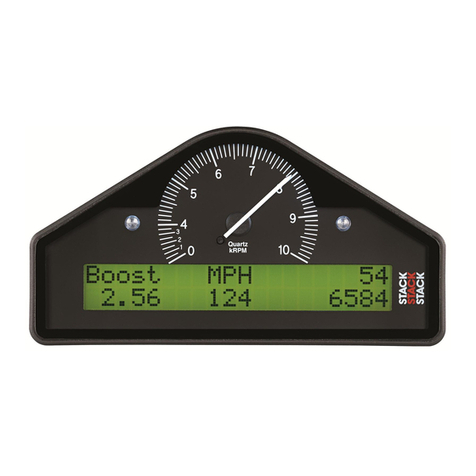
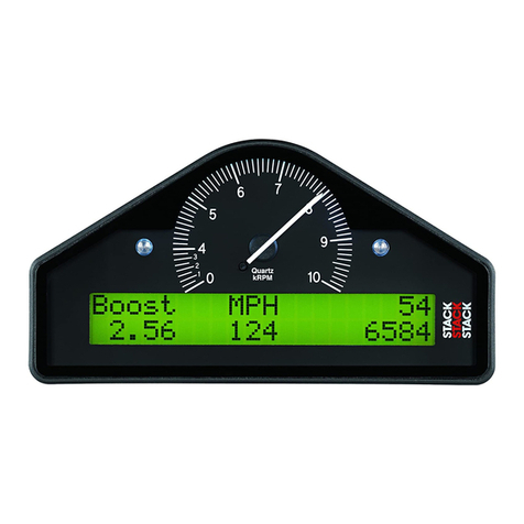
The Display Module consists of an analogue tachometer, two indicator
lights and a digital display panel.
The Display Module is connected to a variety of sensors by a wiring
harness. The wiring harness has a 19-way military connector for
connection to the Display Module.

Chapter 2. Getting Started STACK ST8130 Series Road Car Display Systems
6Users Guide
Wiring Harness
Each of the wires in the harness is labelled.
Labels on Short Cables Connection To
S1 to S4 Switches 1 to 4
WS Wheel speed input (ST492 or ST670)
SL Gear shift warning light
AL Alarm warning light
NET Data logging expansion pack
LAP Optional in-car lap timing sensor (Std on ST8130M)
Labels on Long Cables Connection To
A Air temperature sensor (optional on ST8130 variant)
Fuel pressure sensor (ST8130P/M variants)
ES Engine speed (RPM)
OT Oil temperature sensor
WT Water temperature sensor
OP Oil pressure sensor
F Fuel level sensor
B + 12v Supply (Battery)
B - Battery negative (Chassis)

STACK ST8130 Road Car Display System Chapter 2. Getting Started
Users Guide 7
Connecting the Components
1. Connect the wiring harness to the display module.
2. Connect the four switches to the cables labelled S1 to S4.
3. Connect each of the sensors that you have purchased to the
appropriate wire in the wiring harness, as shown above.
4. Connect a 12v DC power supply or battery to the power input cable.
Never use a battery charger to supply power to the display module.
5. Switch on the 12v DC power supply.
The Display Module should start up with an alarm signal indicating low
oil pressure.
Note that whenever a warning message is shown on the top line of the
digital display, the speed of the vehicle always continues to be shown in
the centre of the bottom line.
You can now proceed to familiarise yourself with operating the Display
Module.

Chapter 3. Operating the Display System STACK ST8130 Series Road Car Display Systems
8Users Guide
Chapter 3. Operating the Display System
This chapter takes you through the operation of the system so that you
can familiarise yourself with its use before you install it in the vehicle.
Switching the Display System on
You will have switched the system on already if you have followed the
instructions in the previous chapter and have just set the system up for
the first time before installing it.
When installed in the vehicle, the system is switched on when you switch
the ignition on.
When the power is first switched on, the digital display will immediately
show a "Low Oil P" warning and the alarm light will come on. The
tachometer will reset itself by moving the needle until it touches the stop-
pin and then moving it back to the zero RPM position. Press Switch 3 to
clear the warning message from the display. (Switch 2 can also be used
for this.)
The digital display panel and the analogue dial face are always backlit
when the system is switched on.
If none of these actions occurs when you switch on, switch off the power
to the system and consult the section on troubleshooting in this manual.
Changing the display layers
The digital display has five display layers. Each display layer shows
three parameters and their values
Each of the display layers is displayed in turn by pressing switch 3. Press
switch 3 when display layer 5 is being displayed in order to return to
display layer 1.
ÖThe format of the values in these displays will vary for
systems supplied outside the UK, as the parameters are
displayed in different units.

STACK ST8130 Series Road Car Display Systems Chapter 3. Operating the Display System
Users Guide 9
Display Layer 1
Display layer 1 shows:
•Fuel level
Note that when the amount of fuel in the tank is changed the
displayed value changes slowly (about 1 litre every 5 seconds) to
minimise the effects of fuel surge.
•Current speed (MPH or km/h)
•Trip indicator
•Odometer
Note that when the UK version has been configured to show the speed in
km/h, the trip and odometer continue to display distances in miles.
Press Switch 3 to see display layer 2.
Display Layer 2 (ST8130 & P variant)
Oil T MPH Oil P
110 C 135 90
Display layer 2 shows:
•Oil temperature (Oil T)
•Current speed (MPH or km/h)
•Oil pressure (Oil P)

Chapter 3. Operating the Display System STACK ST8130 Series Road Car Display Systems
10 Users Guide
Note that the minimum oil and water temperature for which the display
gives a true reading is 12°C or 53°F. The unit displays temperatures that
are less than this as 0°C or 32°F.
Display Layer 2 (ST8130M variant)
Water MPH Oil P
75 C 135 90
ST8130M display layer 2 shows:
•Water temperature
•Current speed (MPH or km/h)
•Oil pressure (Oil P)
Press Switch 3 to change display to layer 3
Display Layer 3 (ST8130 & P variant)
Water MPH Oil P
75 C 135 90
Display layer 3 shows:
•Water temperature
•Current speed (MPH or km/h)
•Oil pressure (Oil P)
Display Layer 3 (ST8130M variant)
Oil T 12.6V Fuel P
110 C 135 65
ST8130M display layer 3 shows:
•Oil temperature (Oil T)
•Battery Voltage

STACK ST8130 Series Road Car Display Systems Chapter 3. Operating the Display System
Users Guide 11
•Fuel Pressure (Fuel P)
•Current speed (MPH or km/h)
Press Switch 3 to display layer 4.
Display Layer 4 (ST8130 variant)
Air T MPH Batt
5 C 135 12.6V
•Air temperature (Air) (optional)
•Current speed (MPH or km/h)
•Battery Voltage (Batt)
Press Switch 3 to change the display either to layer 5 if you have the lap
timing kit installed or back to layer 1.
Display Layer 4 (ST8130P variant)
Fuel P MPH Batt
65 135 12.6V
ST8130P display layer 4 shows:
•Fuel Pressure (Fuel P)
•Current speed (MPH or km/h)
•Battery Voltage (Batt)
Display Layer 4 (ST8130M variant)
Lap 12 MPH Best
1:35.10 135 1:35.06
ST8130M display layer 4 shows:
•Number of the current lap

Chapter 3. Operating the Display System STACK ST8130 Series Road Car Display Systems
12 Users Guide
•Current speed (MPH or km/h)
•Last lap time
•Previous best lap time
Press Switch 3 to change the display to layer 5.
Display Layer 5
Lap 12 MPH Best
1:35.10 135 1:35.06
Display layer 5 shows:
•Number of the current lap
•Current speed (MPH or km/h)
•Last lap time
•Previous best lap time
Lap time can be recorded manually using Switch 4 or with the optional
lap timing kit.
Display Layer 5 (ST8130M variant)
- >< +
1:19:88 135 00.00
ST8130M display layer 5 shows:
•A graphical comparison of this lap to a previously selected lap
•Running time from start of lap
•Current speed (MPH or km/h)
•Relative time of this lap to a previously selected lap
Press Switch 3 to change the display back to layer 1.
Other manuals for st8130 series
2
Table of contents
Other Stack Monitor manuals
