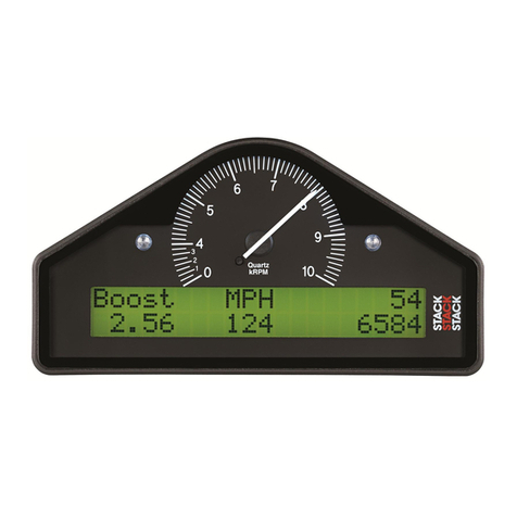
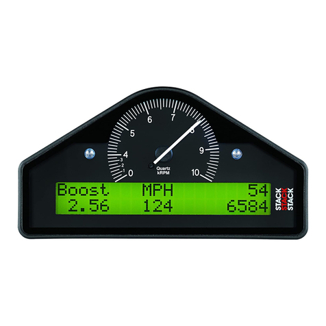
Stack ST8100 User manual

Part No./IssueNo. 542030-004
ST8100 Display SystemST8100 Display System
Users GuideUsers Guide


STACK ST8100 Display System Preface
Users Guide i
PrefacePreface
CongratulationsCongratulations
Congratulations on choosing the Stack ST8100 Display System. This
system will give you a wealth of information to enable you to obtain the
maximum safe performance from your vehicle.
Registration FormRegistration Form
Please complete and return the registration form contained in the
package. This will allow us to keep you up to date on the latest
developments from Stack.
Purpose of this manualPurpose of this manual
This manual will help you install and use the Stack ST8100 Display
System. It explains how to set up and configure the system for your
vehicle.
Edition NoticeEdition Notice
This edition is for all versions of the ST8100 Display System distributed
to customers world wide. The units of measurement used to illustrate the
use of the Display System in this edition are for the UK version. Units
used in the various versions are shown in the following table.
Parameter Type UK Version US Version EC Version
Speed MPH MPH km/h
Temperature Degrees C Degrees F Degrees C
Wheel Circumference Millimetres Inches Millimetres
Pressure PSI PSI Bar

Preface STACK ST8100 Display System
Users Guideii
Related Products From Stack LimitedRelated Products From Stack Limited
If you need information about other Stack motor sport products, these
can be obtained from Stack or from your local Stack dealer. Products
available from Stack include:
•Intelligent Tachometers
•Action Replay Tachometers
•Performance Analysers
•Speedometers
•Boost Gauges
•Analog Sensors
•Digital Sensors
•Data Logging Systems
•Display and Logging Systems
•Radio Telemetry Systems
•Display and Analysis Software
Stack is a registered trademark of Stack Limited.
Information in this publication is subject to change without notice and does not
represent a commitment on the part of Stack Limited. No responsibility is accepted for
error or omission.
Copyright 1994, 1995, 1996 Stack Limited
United Kingdom Telephone Numbers:
Sales: 01 869 240404
Tech Support: 01 869 240420
Fax: 01 869 245500

STACK ST8100 Display System Preface
Users Guide iii
Who to Contact at Stack in Case of DifficultyWho to Contact at Stack in Case of Difficulty
Stack and its approved distributors provide a comprehensive Technical
Help service to assist with your enquiries. Contact your local Stack
branch or distributor.
Approved Stack DistributorsApproved Stack Distributors
Australia Hanco Motor Sport, Factory B2, 2 Healey Road,
Dandenong, Vic 3175.
Tel: 018 312-866 Fax: (3) 794-9959
Belgium Van Den Bossche, B.V.B.A, Boomsesteenweg 62, 2630
Aartselaar.
Tel: 03 877 30 40 Fax: 03 887 24 52 GSM: 003275 42 96 37
Canada Orion Racing, 2270, Industrial(Laval) Montreal, H7S 1P9
Tel: (514) 667 9769 Fax: (514) 667 6320
France Danielson Equipment, 5 Rue de Champ Magny BP2 ZI
58470, Magny Cours.
Tel: 86 21 22 55 Fax 86 21 22 65
Oreca Co., Parc D'Activite de Signes, 83870, Signes.
Tel: 94 32 80 00 Fax 94 32 80 01
Germany ISA Racing, Neustraße 11, 5442 Mendig/Obermendig.
Tel: 26 52 30 61 Fax: 26 52 43 77
Holland Verlinden Technology, Rietdekkersdreef 726, 7328 AL A
Apeldoorn
Tel: (31) 055-5427050 Fax: (31) 055-5427050
Italy Gi Effe di Ghislieri & Csas, Via San Giuliano 39, 15040
Castelceriolo (AL)
Tel: 0131 585 215 Fax 0131 585 454
Sparco SRL., Via Lombardia 5-7, 10071 Borgaro Torinese.
Tel: 11 461 1911 Fax 11 461 1900

Preface STACK ST8100 Display System
Users Guideiv
Japan SARD Co, 50 Kamisotone, Higashimachi Wakabayashi,
Toyotashi, Aichiken 473.
Tel: 0565 53 1166 Fax: 0565 52 5482
New Zealand Allport Motorsport, 5B Olive Road, P.O. Box 12-051,
Penrose, Auckland.
Tel: (9) 579-0113 Fax: (9) 579-0114
South Africa Automotive Technology Specialists (Pty) Limited,
Private Bag, X26, Auckland Park 2006.
Tel: (011) 726-6314 Fax (011) 726 2160
Spain Kernel Technica Auxiliares SA, Muntaner 83-A, 08011
Barcelona.
Tel: (9) 3 544 404 Fax: (9)3 535 812
Motosport International Dream Machine S.L.,Av. Dr.
Wakeman 52 Bajo Der., 46013 Valencia.
Tel: (9)6 333 2044 Fax (9)6 334 7376
Switzerland HORAG, Hotz Racing AG, Kreuzlingenstrasse 3, 8583
Sulgen.
Tel: (072) 42 80 20/21 Fax (072) 42 80 30
UK STACK Ltd,
Wedgwood Road, Bicester, Oxfordshire, OX6 7UL.
Tel: 01869 240404. Fax 01869 245500
Technical Support: 01869 240420
Demon Tweeks,
75 Ash Road South, Wrexham Industrial Estate, Wrexham,
Clwyd. LL13 9YE
Tel: 01978 664 466 Fax 01978 664 467
Gould Engineering Services,
19 Porchester Road, Newbury. Berkshire
Tel: 01635 44466 Fax 01635 30056
P.J. Motorsport, 8 Gypsum Way, Draycott-in-the-Clay,
Ashbourne, Derbyshire,
Tel: & Fax 01283 820625

STACK ST8100 Display System Preface
Users Guide v
Prodrive Ltd, Acorn Way, Banbury, Oxon, OX16 7XS.
Tel: 01295 273355 Fax 01295 271188
Road & Racing Accessories Ltd,
75-77 Moore Park Road, London SW6 2HH.
Tel: 0171.736 2881 Fax 0171 736 6116
V & M Racing, Lower Place Mill, Shaw Road, Newhey,
Rochdale, OL6 3SR.
Tel: 01706 840066 Fax 01706 882437
U.S.A. Stack Inc.
5835A Live Oak Parkway, Norcross, GA, 30093 USA.
Tel: Sales(770) 447 0067 Fax (770) 447 0305
Tech Support (770) 449 8246
B.R.I.T.S. Inc.,
28921 Arnold Drive, Unit F-6, Sonoma, CA 95476.
Tel: (707) 935 3637 Fax (707) 935 0942
Dave Schultz Racing, 1871 Ortiz, Fort Myers, FL 33905.
Tel: (813) 332-1918 Fax (813) 332 5636
Epic Racing, 3088 NW 28th Ave.
Boca Raton FL
Tel: (407) 479 4766 Fax: (407) 479 3398
Landmark Motorsports,
2411 East Winston Road, Anaheim CA 92806
Tel : (714) 776 9400 Fax: (714) 776 9439
Linder Brothers,
6748 County Road 9, Edison, OH 43320
Tel : (419) 947 3226 Fax : (419) 947 2305
Transatlantic Racing Services Ltd,
5730, Chattahoochee Ind. Park, Cumming, GA 30131.
Tel: (770) 889 0499 Fax (770) 889 0657

Preface STACK ST8100 Display System
Users Guidevi

STACK ST8100 Display System Contents
Users Guide vii
ContentsContents
PREFACE i
Related Products From Stack Limited ii
Who to Contact at Stack in Case of Difficulty iii
Approved Stack Distributors iii
CONTENTS vii
Chapter 1. Introducing the Display System 1
How to Use this Manual 2
Chapter 2. Getting Started 3
The Display Module 4
Wiring Harness 4
Connecting the Components 5
Chapter 3. Operating the Display System 6
Switching the Display System on 6
Changing the display layers 6
Peak Values (Tell Tales) 11
Alarms 13
Lap times 15
Gear shift light 16
Chapter 4. Configuring the Display System 17
Configuration mode 17
Leaving configuration mode 20
Chapter 5. Installing the Display System 21
Who can install the Display System? 21
Tools needed to install the Display System 21
Preconfigured Display Systems 21
Custom Configured Display Systems 21
Fitting the Display Module 22
Switches 23
Warning lights 24
Engine Speed (RPM) Measurement 24
Connecting the Display System to the Ignition System 25

Contents STACK ST8100 Display System
Users Guideviii
Pressure sensors 29
Temperature sensors 30
Wheel speed sensor (optional) 32
Lap timing sensor (optional) 33
Trackside Infra-Red Lap Beacon (optional) 34
Lateral Acceleration sensor (optional) 35
Wiring harness 36
Checks and Alarms 37
Chapter 6. Troubleshooting 38
Appendix A. Template for the Display Module 49
Appendix B. Wiring Harness Schematic Diagram 52
Returned Goods Form 53
Appendix D. Summary of Switch Functions 54
INDEX 55

STACK ST8100 Display System Chapter 1. Introducing the Display System
Users Guide 1
Chapter 1. Introducing the Display SystemChapter 1. Introducing the Display System
The Stack ST8100 Display System monitors and displays a range of
values, known as performance parameters, needed for effective car and
driver management in most competitive situations.
The system combines an analog tachometer with a digital display for the
following performance parameters:
1. Engine speed (RPM)
2. Oil pressure
3. Oil temperature
4. Water temperature
5. Fuel pressure
6. Battery Voltage
7. Wheel speed (optional)
8. Lap times (optional)
9. Lateral Acceleration (optional). This option is used only in conjunction
with the optional logging system. The information from it is not
displayed on the Display Module.
10. Maximum and minimum corner speeds display(optional)
You can view the peak values (tell-tales) for all the parameters.
The system provides a range of warning messages based on preset alarm
values for the following performance parameters:
1. Oil pressure
2. Oil temperature
3. Fuel pressure
4. Water temperature
5. Battery voltage
You can enable or disable the warning system for each parameter
individually.

Chapter 1. Introducing the Display System STACK ST8100 Display System
2Users Guide
You can redefine the preset alarm value for each parameter to a value
that is more suitable for your vehicle.
The system provides a gear shift warning light that is based on an RPM
value that you define for your vehicle.
How to Use this ManualHow to Use this Manual
Stack recommends that you unpack and connect the components in the
system before you install it in your vehicle. This will enable you to
familiarize yourself with operating the display and configuring it for the
vehicle in which you intend to install it.
This manual starts by taking you through the process of setting up the
system before installation, operating the digital display, configuring the
system and setting the alarm values, and installing it in the vehicle. By
the end of chapter 2, you will have set up the system so that you will be
assured that it is functioning normally. You can then read chapter 3 and
practice using its functions. Chapter 4 takes you through configuring it
for your vehicle. Chapter 5 explains how to install it in the vehicle.
Chapter 6 provides a set of trouble-shooting guidelines.
A template for the Display Module dashboard cut-out is provided in
Appendix A and a schematic diagram of the wiring harness is in
Appendix B.
Please note that this manual does not attempt to explain how to
interpret or use the information from the ST8100 Display System, as this
is very specific to the type of vehicle in which it is installed and the type
of competition in which the vehicle is engaged.

STACK ST8100 Display System Chapter 2. Getting Started
Users Guide 3
Chapter 2. Getting StartedChapter 2. Getting Started
This chapter guides you through the initial unpacking and setting up of
the equipment for pre-installation checks and familiarization with its
operation.
Standard ST8100 Display System ItemsStandard ST8100 Display System Items
The ST8100 Display System is supplied with the following standard
components:
Quantity Description
1Display Module (ST86x ) with 2 mounting brackets
1Wiring Harness (ST872 )
2Pressure Sensors (ST744, ST745, ST746)
2
Temperature Sensors (ST760, ST761, ST762, ST763, ST764)
4Switches (supplied with and to be connected to the wiring
harness)
Optional ST8100 Display System ItemsOptional ST8100 Display System Items
The ST8100 Display System can be used with the following optional
components:
Quantity Description
1RPM Sensor (ST696 Opto Isolator or ST697 H.T. Pick-up)
1Wheel Speed Sensor (ST670)
1Infra-red Lap Time Receiver (ST543)
1Infra-red Lap Time Beacon (ST544)
1External Gear Shift Warning Lamp
1External Alarm Warning Lamp
1Corner Speed option. Note: The ST8109 Corner Speed option
is delivered prefitted in the Display Module.

Chapter 2. Getting Started STACK ST8100 Display System
4Users Guide
The Display ModuleThe Display Module
The Display Module consists of an analog tachometer and a digital
display panel.
The Display Module is connected to a variety of sensors by a wiring
harness. The wiring harness has a 19-way military connector for
connection to the Display Module.
Wiring HarnessWiring Harness
Each of the wires in the harness is labelled.
Labels on short cables Connection To
S1 to S4 Switches 1 to 4
WS Wheel speed sensor
LAP Lap timing sensor
SL Gear shift warning light
AL Alarm warning light
NET Data logging expansion pack

STACK ST8100 Display System Chapter 2. Getting Started
Users Guide 5
Labels on Long Cables: Connection To
ES Engine Speed (RPM)
OT Oil temperature sensor
WT Water temperature sensor
OP Oil pressure sensor
FFuel pressure sensor
ALateral Acceleration sensor
B + Battery Positive
B - Battery Negative (Earth)
Connecting the ComponentsConnecting the Components
1. Connect the wiring harness to the Display Module.
2. Connect the four switches to the cables labelled S1 to S4.
3. Connect each of the sensors that you have purchased to the
appropriate wire in the wiring harness, as shown above.
4. Connect a 12v DC power supply to the power input cable.
5. Switch on the 12v DC power supply.
The Display Module should start up with an alarm signal indicating low
oil pressure.
This is normal in this environment.
You can now proceed to familiarize yourself with operating the Display
Module

Chapter 3. Operating the Display System STACK ST8100 Display System
6Users Guide
Chapter 3. Operating the Display SystemChapter 3. Operating the Display System
This chapter takes you through the operation of the system so that you
can familiarize yourself with its use before you install it in the vehicle.
Switching the Display System onSwitching the Display System on
You will have switched the system on already if you have followed the
instructions in the previous chapter and have just set the system up for
the first time before installing it.
When installed in the vehicle, the system is switched on when you switch
the ignition on.
When the power is first switched on, the digital display will immediately
show a "Low Oil P" warning and the alarm light will come on. The
tachometer will reset itself by moving the needle until it touches the
stop-pin, and then moving it back to the zero RPM position. Press Switch
3 to clear the warning message from the display. (Switch 2 can also be
used for this.)
The digital display panel and the analog dial face are always backlit
when the system is switched on.
If none of these actions occurs when you switch on, switch off the power
to the system and consult the section on troubleshooting in this manual.
Changing the display layersChanging the display layers
The digital display can show three separate sets of parameters and their
values; these are called display layer 1, display layer 2, 3 and 4.
If you have the Corner Speed option, there is an additional layer, layer 5,
which displays corner speed data.
Each of the display layers can be displayed in turn by pressing switch 3.
Press switch 3 when display layer 4, or layer 5 if you have the Corner
Speed option, is being displayed in order to return to display layer 1.

STACK ST8100 Display System Chapter 3. Operating the Display System
Users Guide 7
ðThe format of the values in these displays will vary for
systems supplied outside the UK, as the parameters are
displayed in different units.
Display Layer 1Display Layer 1
Display layer 1 shows:
•Water Temperature (WATER)
•Oil temperature (OIL T)
•Current speed (SPEED).
•Oil Pressure (OIL P)
Note: OILT is replaced by BOOST on the Boost Pressure version of the
display system.
Press Switch 3 to see display layer 2.
Display Layer 2Display Layer 2
Display layer 2 shows:
•Battery voltage (BATT)
•Oil Temperature (OIL T)
•Fuel Pressure (FUELP)

Chapter 3. Operating the Display System STACK ST8100 Display System
8Users Guide
•Oil Pressure (OIL P)
Note: The fuel pressure is displayed as 0.1 PSI (US and UK) and as 0.01 Bar
(EU) on the Low Fuel Pressure version of the display system.
Press Switch 3 to change display to layer 3
Display Layer 3Display Layer 3
Display layer 3 shows:
•Lap number (LAP No) of last completed lap
•Lap time for last completed lap
•Current Speed (SPEED)
•Fastest lap time (BEST) (only the seconds and milliseconds parts of
the lap time are shown)
Press Switch 3 to display layer 4.
Display Layer 4Display Layer 4
Display layer 4 shows:
Top Row
•Best lap time
•Running time from start of lap
•Relative time of this lap to a previously selected lap (this feature is
active only if the Performance Meter has been purchased).
•Bottom Row
•A graphical comparison of this lap to a previously selected lap (this
feature is active only if the Performance Meter has been purchased).

STACK ST8100 Display System Chapter 3. Operating the Display System
Users Guide 9
Press Switch 3 to change the display back either to layer 1 or to layer 5 if
you have the Corner Speed option.

Chapter 3. Operating the Display System STACK ST8100 Display System
10 Users Guide
Display Layer 5Display Layer 5
This display is available when the optional Corner Speed feature is
installed.
Display layer 5 shows:
•Current speed (SPEED)
•Maximum speed straight (MAX)
•Actual speed when Switch 1 was last pressed (HOLD)
•Lowest speed attained in the previous corner (MIN)
Press Switch 3 to display layer 1 again.
Other manuals for ST8100
1
Table of contents
Other Stack Monitor manuals
