Staffs Fitness b1-attack User manual
01538 387960
USER MANUAL
Brake Pad Indoor Bike

01538 387960
USER MANUAL
IMPORTANT SAFETY INSTRUCTIONS
PLEASE SAVE THESE INSTRUCTIONS
READ ALL INSTRUCTIONS BEFORE USING THIS EXERCISE EQUIPMENT.
Keep infants and young children off your bike at all times.
Any child using the bike should be supervised by an adult.
When the bike is in use, young children and pets should be kept at least 10 feet away.
Use this bike only for its intended use as described in the manual.
Keep your hands away from all moving parts, never turn the pedal crank arms by hand.
Do not remove your feet from the pedals while they are in motion.
Do not dismount the bike until both the pedals and flywheel have come to a complete
stop.
Do not attempt to use this bike at high speeds or in standing positions until you have
practiced and are comfortable at lower speeds.
After exercising, push down on the tension knob or turn the tension knob in a clockwise
direction to slow the flywheel down and decrease the potential for injury.
Rotate the tension knob clockwise to add resistance to the flywheel prior to standing
on the pedals.
Never drop or insert any object into any opening on this bike.
Do not use without proper footwear.
To assure that the safety level of this bike is maintained, examine components for wear
and tear on a regular basis. Components that are worn excessively or inoperable should
be replaced immediately or the bike should be put out of use until it is repaired.
CAUTION:
If you experience chest pains, nausea, dizziness or shortness of breath, stop exercising
immediately and consult your physician before continuing.

01538 387960
INSTRUCTIONS FOR USE
The B1 Attack indoor bike is designed to be used as a group bike in fitness studios and
health clubs. It has a fixed driven flywheel and should only be used under professional
supervision.
Installation – it is important that the B1 Attack indoor bike is correctly assembled and we
recommend that installation and assembly be carried out by suitably qualified personnel.
Handlebar and seat adjustment. It is important that the handlebar and seat are set at the
height correct for your body. Ask your instructor for assistance.
Adjusting the handlebar height - Make sure it is securely tightened and that there is no
lateral or vertical movement of the handlebar. Undo the quick release lever which is
located in front of main tube. Slide thr stem tube in an upward or downward movement
to the required height position then re-tighten again.
Adjusting the seat height – refer to above mention.
The stem/sliding tube position can also be adjusted forwards or backwards. Undo the
quick release lever located underneath of the bottom of sliding tube.
Slide the handlebar/top sliding tube in forwards or backwards motion until it reaches the
required position then securely re-tighten the quick release lever.
The seat/slider position can also be adjusted forwards or backwards. Undo the quick
release lever located underneath the bottom slider.
Slide the seat/top slider forwards or backwards until it reach the required position then
securely re-tighten the quick release lever.
NOTE: There is a safety line engraved on the seat post and handlebar stem. On no
account should the seat post or handlebar stem ever be raised above this line.
Pedals and toe straps – your feet should be securely positioned in the toe clips during the
exercise. Put your foot as far forward as you can into the toe-clip and then pull the strap
tight.
Resistance System - The B1 Attack indoor bike has a durable belt direct drive
transmission system, to adjust the exercising resistance on the completed spinning bike,
undo the simply loosen or tighten using the control lever to make the adjustment.
For an emergency stop then push the control lever up-ward to the hardest position for
stopping the wheel.
The B1 Attack indoor bike should operate on a level surface with no lateral movement.
There are height adjustable pads located on either side underneath of front and rear
ground tube.
Maintenance – like any other mechanical cycling device, the B1 Attack indoor bike should
be regularly maintained. Ask your supplier for a detailed maintenance programme.
1).
2).
3).
4).
5).
6).
7).
01538 387960
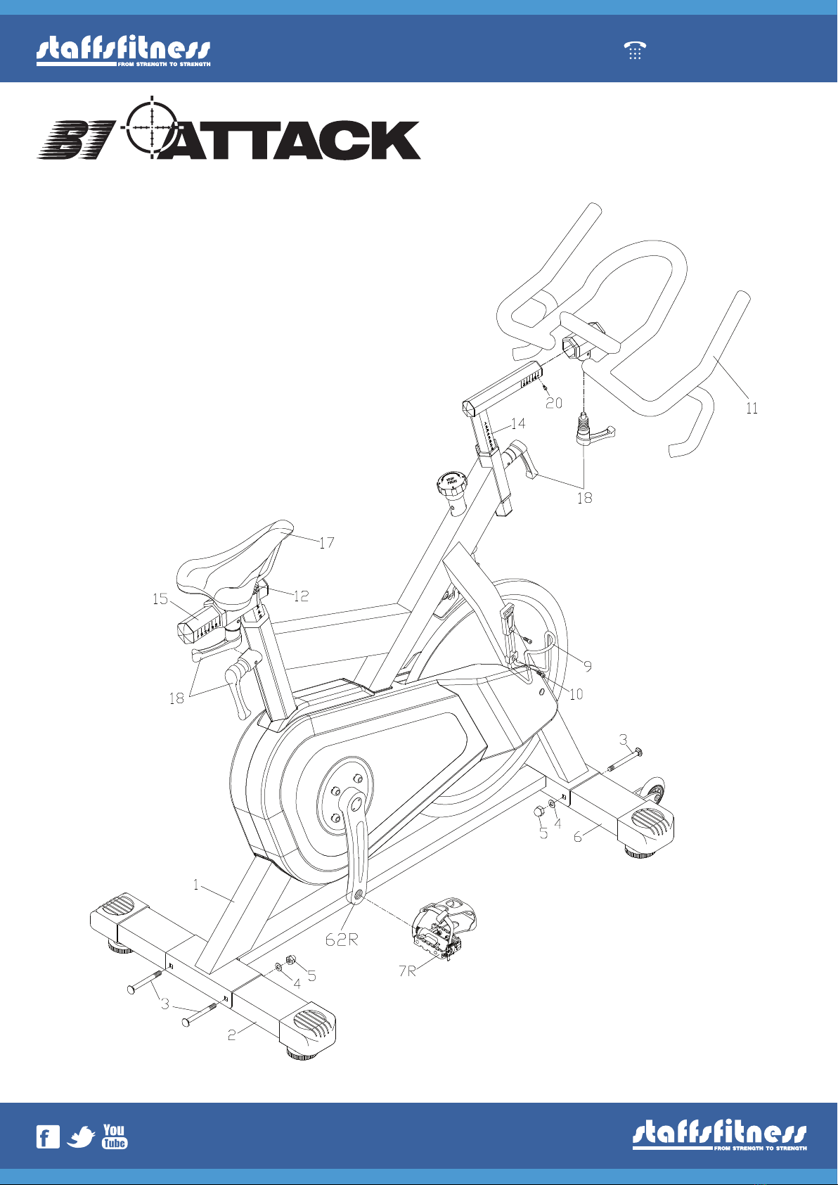
ASSEMBLY DIAGRAMS
Brake Pad Indoor BikeBrake Pad Indoor Bike

STEP 3
01538 387960
Step 1. (foot)
Attach the front foot (6) to the frame using the bolt (3), washer (4)
and nut (5).
Step 2. (foot)
Attach the rear foot (2) to the frame using the bolt (3),
washer (4) and nut (5).
Step 3. (pedals)
Attach the pedals (7R/7L) into the crank arms (62R/62L), Each
pedal is marked with the letter R (right) or L (left) to denote the
side of the bike that they are on. NOTE: the right hand crank is on
the same side as the right belt cover (72). Be careful to align the
threads correctly to avoid any damage. A little grease on the
thread should help the pedals to screw in easily and correctly.
Tighten using a 15mm spanner, both pedals threads should
tighten towards the front of the bike.
ASSEMBLY
STEP 1
STEP 2
STEP 3

01538 387960
Step 4. (handlebar & stem)
Open the screw (20) then attach the handlebar (11)
onto the handle bar stem (14).
Slide the handle bar until you rach the required
position then use the lock lever (18) tighten.
Screw back the safety screw (20) to sliding tube.
Assemble the stem onto the front of the head tube.
Then use the lock lever (18) to tighten.
Open the stem lock lever (18) to adjust stem and
handlebar height to your ideal position
use the lock lever (18) to tighten. NOTE: Do not
assemble above the safety line.
Step 5. (saddle & seat post)
Assemble the seat post onto the frame seat tube
then use the lock lever (18) to tighten it.
Open the screw (20) then insert the seat post (15)
into the frame's seat tube.
Assemble the saddle (17) on to the saddle top slider
(16) then tighten the saddle clamp (12) to fix the
saddle. Slide the saddle forwards or backwards
until a it is in the correct position then use the lock
lever (18) to tighten and then screw back the safety
screw (20) Adjust the seat post (15) height at a
proper position then use the lock lever (18)
to tighten.
NOTE: Do not assemble above the safety line.
STEP 4
STEP 5

01538 387960
Step 6. & 7. (bottle cage)
Attach the bottle cage on to the front fork in the required position then assemble the bottle
cage onto the front fork with the Allen key bolt (10)
Use the Allen key tool to tighten the bolt to fix the bottle cage onto the front fork.
STEP 6 STEP 7

01538 387960
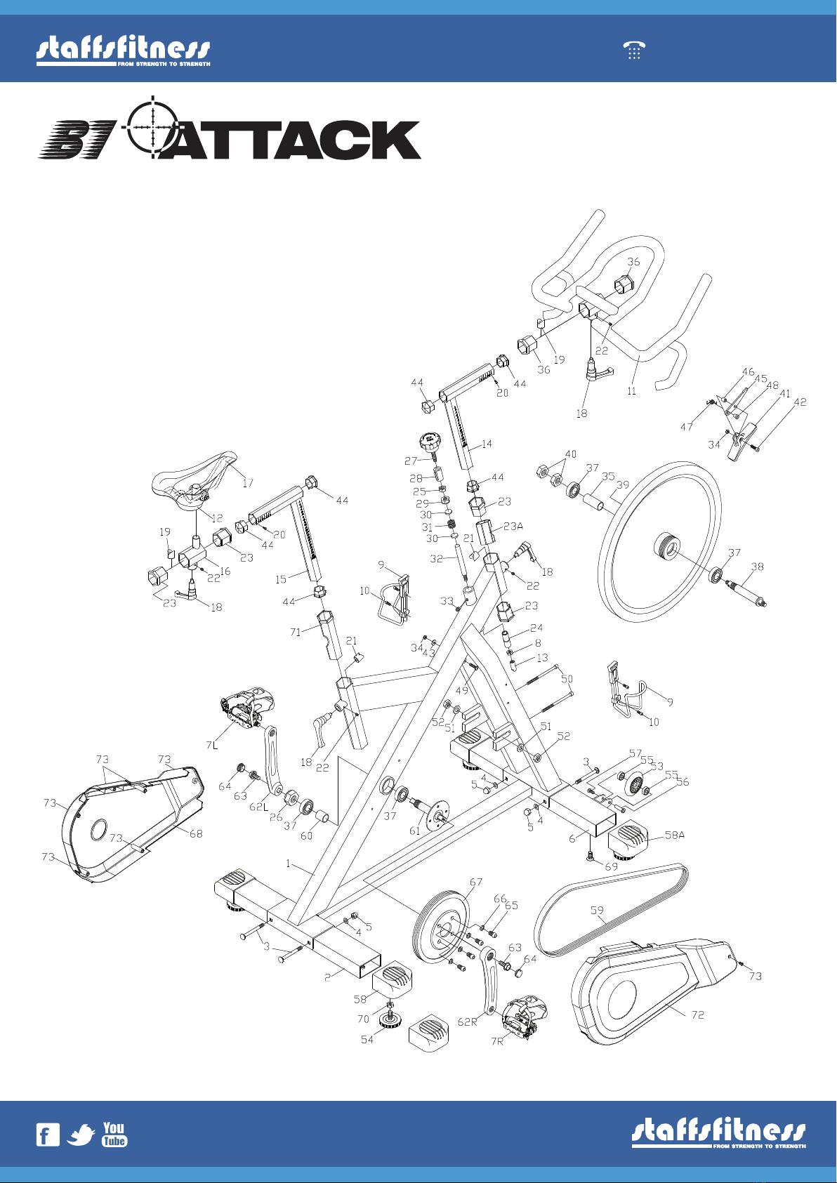
PARTS LIST
Part No. Descripon Q'ty Part No. Descripon Q'ty
1 Main Frame 1 38 Fly Wheels Axle 25/20/155.5 L 1
2 Rear Ground Tube 1 39 Fly Wheel 480/21kgs 1
3 Groung Tube Fixed Bolt 4 40 Lock Nut M17/1.0/8t 2
4 Washer 4 41 Brake Pad 1
5 Nut 5 42 Screw M6/p 1.0/20l 1
6 Front Ground Tube 1 43 Washer 13/6/1.5t 1
7 R/l Pedal 1 44 End Plug 38mm/2.5t 3
8 Nut M8/p1.25 1 45 Brake Arm 1
9 Bole Cage 2 46 Sleeve 10 Od/6.2/6.2l 1
10 Bole Cages Fixed Screw 4 47 Spring 1.5d/4.5l 1
11 Handlebar 1 48 Sleeve14d/14.9l 1
12 Saddel Clamp 1 49 Bolt M6/p1.0/30 L 1
13 End Plug For Stem/post 3 50 Adjustments Screw M6/p1.0/120l 2
14 Stem 1 51 Washer 25od/10id/3t 2
15 Seat Post 1 52 Nut M12/p1.5/10t 2
16 Saddles Slider 1 53 Pu Moving Wheel 64mm 2
17 Saddle 1 54 Ground Tube's Pad 4
18 Lock Lever 4 55 Bearing 608zz 4
19 Lock Nut 23/23 length 2 56 Bolt Nut 8/30l W/m6/p1.0 2
20 Screw M5/p0.8/10 length 2 57 Bolt Nut M6/p1.0/12l 2
21 V Block 2 58 Rear Ground Tube End Cap 2
22 V Blocks Fixed Screw M6/p1.0/8l 4 58a Front Ground Tube End Cap 2
23 Plasc Sleeve 50mm/38mm 5 59 Belt 1
23a Plasc Sleeve 45mm/72l/2.5 thread 1 60 Sleeve 27od/20.1id/27l 1
24 Nylon Sleeve 1 61 B.B Axle 25mm/20mm/116.5l 1
25 Nut 3/8" X16tpi X 6t 1 62l LeCrank 170l 1
26 Nut M20/1.0/12 thread 1 62r Right Crank 170l 1
27 Adjust Knob 1 63 Screw M8/p1.0/20l 2
28 Moving Part 20 Od/34l 1 64 Dusty Cover 2
29 Lock Nut M8/p1.25 1 65 Bolt M10/p1.5/15l 4
30 Round Plate 20mm/3t 2 66 Spring Washer 4
31 Spring 19mm/2.3mm/20l 1 67 Pulley 210/5pk/20.5t 1
32 Upper Stud 12.7 D/100/28l 1 68 LeBlet Cover 1
33 Guide Screw M8/p1.25/8l 1 69 Bolt Nut 2
34 Nut M6/p1.0 1 70 Nut 3/8"/p1.6/6t 1
35 Spacer 24 Od/20.1 Id/50.7l 1 71
Seat Tube's Sleeve
1
36 Sleeve 56mm/38mm 2 72 Right Blet Cover 1
37 Bearing 6004 zz 4 73 Screw M5/p0.8/10l 5
Brake Pad Indoor Bike
l Length
t Thread
zz Bearing No.
pk Belt No.
01538 387960
EXPLODED DIAGRAM
Brake Pad Indoor Bike

01538 387960
NOTES
Brake Pad Indoor Bike
To purchase any items fo your B1 Brake Pad indoor Bike
call us on 01538 387960
This manual suits for next models
1
Table of contents
Other Staffs Fitness Exercise Bike manuals

Popular Exercise Bike manuals by other brands


Sunny Health & Fitness
Sunny Health & Fitness SF-B121021 user manual

Monark
Monark 827E instruction manual

Stamina
Stamina 1310 owner's manual

American Fitness
American Fitness SPR-BK1072A owner's manual
 Service manual")
Cateye
Cateye CS-1000 (CYCLO SIMULATOR) Service manual

BH FITNESS
BH FITNESS H9158H Instructions for assembly and use