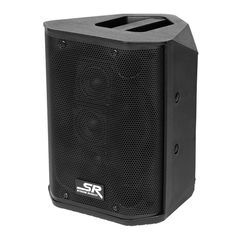
Stage right miniray 12 User manual

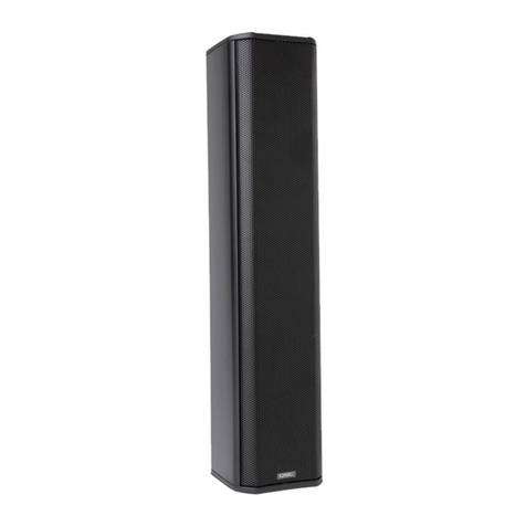
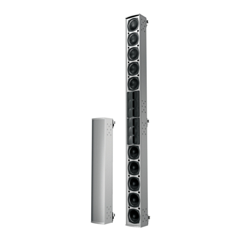
MiniRay™ 652 300W
Active Line Array Speakers (604926)
MiniRay™A1
Line Array Suspension Bracket (604900)
MiniRay™12 700W
Active Line Array Subwoofer (604912)
User’s Manual and Suspension Guide


2
CONTENTS
SAFETY WARNINGS AND GUIDELINES ...................................................................................................................................................................................3
INTRODUCTION...........................................................................................................................................................................................................................................6
FEATURES.........................................................................................................................................................................................................................................................6
CUSTOMER SERVICE...............................................................................................................................................................................................................................6
PACKAGE CONTENTS.............................................................................................................................................................................................................................7
604926 MiniRay 652 300W Active Line Array Speaker......................................................................................................................................7
604912 MiniRay 12 700W Active Line Array Subwoofer ...................................................................................................................................7
604900 MiniRay A1 Line Array Suspension Bracket..............................................................................................................................................7
PRODUCT OVERVIEW ........................................................................................................................................................................................................................... 8
MR652 MiniRay™ 652 300W Active Line Array Speaker (604926).......................................................................................................... 8
MR12 MiniRay™ 12 700W Active Line Array Subwoofer (604912).............................................................................................................9
ATTACHING CABINETS........................................................................................................................................................................................................................10
RIGGING AND SUSPENSION............................................................................................................................................................................................................11
Rigging Novices..................................................................................................................................................................................................................................11
Rigging/Suspension Hardware.............................................................................................................................................................................................12
Hanging Points...................................................................................................................................................................................................................................12
MAINTENANCE..........................................................................................................................................................................................................................................12
CONNECTING THE SYSTEM.............................................................................................................................................................................................................13
Connecting for Full-Range Operation............................................................................................................................................................................13
Connecting using an Outboard Active Crossover...............................................................................................................................................15
TROUBLESHOOTING..............................................................................................................................................................................................................................16
TECHNICAL SUPPORT ..........................................................................................................................................................................................................................17
GENERAL SPECIFICATIONS .............................................................................................................................................................................................................18
ELECTRICAL SPECIFICATIONS.......................................................................................................................................................................................................19
REGULATORY COMPLIANCE..........................................................................................................................................................................................................19
Notice for FCC ....................................................................................................................................................................................................................................19
Notice for Industry Canada................................................................................................................................................................................................... 20

3
SAFETY WARNINGS AND GUIDELINES
Please read this entire manual before using this device, paying extra attention to these
safety warnings and guidelines. Please keep this manual in a safe place for future reference.
This line array system is intended for indoor use only.
Do not expose this speaker system to water or moisture of any kind. If moisture
does get in or on the system, immediately unplug it from the power source and
allow it to fully dry before reapplying power.
Do not touch the system, the power cord, or any other connected cables with wet
hands.
If operating this speaker system in a humid environment, ensure that no
condensation occurs. Condensation could cause damage to the speaker cones and
could cause a short in the amplifier, which in turn could cause fire or severe electric
shock.
Do not expose this system to excessively high temperatures. Do not install it in
direct sunlight.
This system dissipates excessive heat from the heat sink on the rear. Do not cover
the heat sink and ensure that there is at least 12" space behind the speaker to allow
for adequate air flow.
Keep flammable materials at least 3 feet from the heat sink on the rear of these
speakers.
This system has no user serviceable parts. Do not attempt to open, service, or
modify any part of it.
Before attempting to suspend the MiniRay™ System, please read and understand
this safety information. Never attempt to outwit your own common sense. If you do
not understand how to rig or suspend heavy equipment, DON'T DO IT!
Always consult with a licensed structural engineer regarding placement and load
points of the facility to which this system will be attached. Monoprice assumes no
liability for damages or injury due to improper rigging techniques. Anyone using this
information assumes all liability arising from use.

4
All information presented herein is based upon common materials and practices.
The installer must comply with all local/state regulations regarding the suspension
of active sound systems. Users should consult with engineering and regulatory
authorities for specific guidelines.
Before suspending any speaker system always inspect all components (enclosure,
rigging frames, pins, etc.) for cracks, deformations, corrosion, missing, or loose or
damaged parts that could reduce the strength and safety of the system. Do not
suspend speakers until the proper corrective action has been taken. Use only load-
rated hardware when suspending any loudspeakers.
Any hardware used in an overhead suspension application must be load rated for
the intended use. Local hardware stores do not usually stock these products.
Purchase additional suspension hardware from rigging supply houses; industrial
supply catalogs, or specialized rigging distributors.
A licensed Structural Engineer must approve the placement and method of
attachment to structures prior to installation of any overhead object. Your
Structural Engineer must answer to the following codes: Uniform Building Code,
Municipal Building Code, and Seismic Code, as applicable. Installation of hardware
and the method of attachment must be carried out in the manner specified by the
Structural Engineer. Improper installation may result in damage, injury, or death.
Your MiniRay™System should be inspected for structural integrity at least annually.
The inspection should include a visual survey of all corners and load bearing
surfaces for signs of cracking, deformation, water damage, delamination, or any
other condition that may decrease the strength of the loudspeaker enclosure.
Suspension hardware should be surveyed for signs of corrosion, bending, or any
other condition that may decrease the strength of the fastener. For other fittings
used, refer to the manufacturer's inspection and maintenance guidelines for the
specific process.

5
Monoprice is not responsible for the application of its products for any purpose or
the misuse of this information for any purpose. Monoprice is not responsible for the
abuse of its products caused by avoiding compliance with inspection and
maintenance procedures or any other abuse. Prior to suspending the system, an
expert, trained and experienced in suspending loudspeaker systems, should inspect
all rigging parts and components.
MiniRay™ Active Line Array loudspeakers must only be suspended using the
MiniRay A1 Line Array Suspension Bracket (604900). This system is designed for the
suspension of the MiniRay Active Line Array by a qualified person familiar with
rigging hardware and industry practices. Improper installation will result in damage,
injury, or death.
The MiniRay A1 Line Array Suspension Bracket is only rated for suspending 2x
MiniRay 12 Line Array Subwoofers above 8x MiniRay 652 Line Array Speakers or 12x
MiniRay 652 Line Array Speakers.
Hearing damage can occur when subjected to prolonged exposure to excessive
sound pressure levels (SPL). MiniRay loudspeakers are capable of generating sound
pressure levels (SPL) sufficient to cause permanent hearing damage to performers,
production crew, and audience members. Caution should be taken to avoid
prolonged exposure to SPL in excess of 90 dB.
If you are new to rigging, you should do the following:
Know the rules for safe rigging.
Attend a safe rigging seminar. Most rigging supply stores provide one-day sessions.
Meet and establish a relationship with a licensed mechanical or structural engineer.
Get in the habit of asking them questions instead of guessing about their answers.
Learn from what they tell you.
Let your insurance carrier know you are suspending a new speaker system.
Research and understand the codes, practices, and requirements of the facilities
and cities where you intend to operate your sound system.

6
INTRODUCTION
Thank you for purchasing this MiniRay™ Line Array Audio System! This system includes a
700-watt subwoofer and a 300-watt full range speaker. It is suitable for installation in
facilities that seat up to 1000 people. You can ground stack the system or fly it using the
dedicated suspension bracket. The speakers can be splayed from 0-16.8° in 1.2° increments.
It provides 100° of horizontal dispersion and as little as 10° of vertical dispersion, depending
on how the system is deployed. The subwoofer has a built-in variable low-pass filter and
the speaker has an optional high-pass filter at 150Hz.
FEATURES
Easily connected and operated high fidelity sound system for audiences up to 1000
people
Ground stack or fly ready using the MiniRay™ A1 Line Array Suspension Bracket
(604900)
100° horizontal dispersion
Variable vertical dispersion from 10°, depending on how the system is deployed
0-16.8° splay in 1.2° increments
CUSTOMER SERVICE
The Monoprice Customer Service department is dedicated to ensuring that your ordering,
purchasing, and delivery experience is second to none. If you have any problem with your
order, please give us an opportunity to make it right. You can contact a Monoprice
Customer Service representative through the Live Chat link on our website
www.monoprice.com during normal business hours (Mon-Fri: 5am-7pm PT, Sat-Sun: 9am-

7
PACKAGE CONTENTS
Please take an inventory of the package contents to ensure you have all the items listed
below. If anything is missing or damaged, please contact Monoprice Customer Service for a
replacement.
604926 MiniRay 652 300W Active Line Array Speaker
1x MiniRay™ 652 Active Line Array Speaker (hereafter referred to as MR652)
1x AC Power Cord NEMA 5-15P to NAC3FCA
1x AC Jumper NAC3FCA to NAC3FCB
1x Audio Jumper XLR-F to XLR-M
1x User's Manual
604912 MiniRay 12 700W Active Line Array Subwoofer
1x MiniRay 12 Active Line Array Subwoofer (hereafter referred to as MR12)
1x AC Power Cord NEMA 5-15P to NAC3FCA
1x AC Jumper NAC3FCA to NAC3FCB
1x Audio Jumper XLR-F to XLR-M
1x User's Manual
604900 MiniRay A1 Line Array Suspension Bracket
1x MiniRay A1 Line Array Suspension Bracket (hereafter referred to as MRA1)
1x User's Manual

8
PRODUCT OVERVIEW
MR652 MiniRay™ 652 300W Active Line Array Speaker (604926)
1. Input: Combination XLR / 1/4" TRS balanced line input.
2. Output: XLR balanced through output.
3. Volume: Adjusts the output volume.
4. High-Pass Filter: Enables the 150Hz high-pass filter, which removes low frequencies
from the MR652.
5. Input: NC3 AC power input.
6. Output: NC3 AC power throughput supports up to 1x MR12 and 4x MR652 or 6x
MR652 per run.
7. AC Power: Switches power on and off.
8. Power: LED indicator illuminates when power is applied.
9. Signal: LED indicator illuminates when an audio signal is present.
10. Clip: LED indicator illuminates when the audio material is clipping. Decrease the
volume or lower the output volume of the source material.
11. Protect: Overheat protection LED indicator illuminates when the unit is too hot. The
unit will automatically shut down until it is safe to operate again.
12. Passive Heat Sink: Dissipates heat. Do not cover and allow at least 12" clearance.

9
MR12 MiniRay™ 12 700W Active Line Array Subwoofer (604912)
1. Input: Combination XLR / 1/4" TRS balanced line input.
2. Output: XLR balanced through output.
3. Volume: Adjusts the output volume.
4. Frequency: Variable low-pass filter sets the level at which frequencies higher than
the level are removed from the MR12. Can be set from 50 ~ 250 Hz.
5. Input: NC3 AC power input.
6. Output: NC3 AC power throughput supports up to 1x MR12 and 4x MR652 or 6x
MR652 per run.
7. AC Power: Switches power on and off.
8. Power: LED indicator illuminates when power is applied.
9. Signal: LED indicator illuminates when an audio signal is present.
10. Clip: LED indicator illuminates when the audio material is clipping. Decrease the
volume or lower the output volume of the source material.
11. Protect: Overheat protection LED indicator illuminates when the unit is too hot. The
unit will automatically shut down until it is safe to operate again.
12. Passive Heat Sink: Dissipates heat. Do not cover and allow at least 12" clearance.

10
ATTACHING CABINETS
The MR12 and MR652 cabinets must be suspended using the MRA1 Line Array Suspension
Bracket (604900) by a qualified Structural Engineer using industry practices. Improper
installation will result in damage, injury, or death.
Monoprice is not responsible for the application of its products for any purpose or the
misuse of this information for any purpose. Monoprice is not responsible for the abuse of
its products caused by avoiding compliance with inspection and maintenance procedures
or any other abuse. Prior to suspending the system, an expert, trained and experienced in
suspending loudspeaker systems, should inspect all rigging parts and components.
The bracket supports suspension of the following configurations:
maximum 2x MR12 subwoofers above 8x MR652 speakers OR 12x MR652 speakers
1. The Set Pin (1) connects to the Set Bracket (3) at the front of the cabinet.
2. Insert the Set Pin in one of the Angle Positions (2) for the desired angle, then
connect to one of the holes in the Angle Bracket (4). Add the angles for the Set Pin
at the Angle Position (2) to the hole used in the Angle Bracket (4) to get the total
splay angle for the rear of the cabinet.

11
RIGGING AND SUSPENSION
Before attempting to suspend the MiniRay™ System, please read and understand this
safety information. Never attempt to outwit your own common sense. If you do not
understand how to rig or suspend heavy equipment, DON'T DO IT!
Always consult with a licensed structural engineer regarding placement and load points of
the facility to which this system will be attached. Monoprice assumes no liability for
damages or injury due to improper rigging techniques. Anyone using this information
assumes all liability arising from use.
All information presented herein is based upon common materials and practices. Installers
must consult with all local/state regulations regarding the suspension of active sound
systems. Users should consult with engineering and regulatory authorities for specific
guidelines.
Before suspending any speaker system always inspect all components (enclosure, rigging
frames, pins, etc.) for cracks, deformations, corrosion, missing, or loose or damaged parts
that could reduce the strength and safety of the system. Do not suspend speakers until the
proper corrective action has been taken. Use only load-rated hardware when suspending
any loudspeakers.
Rigging Novices
If you are new to rigging, you should do the following:
Know the rules for safe rigging.
Attend a safe rigging seminar. Most rigging supply stores provide one-day sessions.
Meet and establish a relationship with a licensed mechanical or structural engineer.
Get in the habit of asking them questions instead of guessing about their answers.
Learn from what they tell you.
Let your insurance carrier know you are suspending a new speaker system.
Research and understand the codes, practices, and requirements of the facilities
and cities where you intend to operate your sound system.

12
Rigging/Suspension Hardware
Any hardware used in an overhead suspension application must be load rated for the
intended use. Local hardware stores do not usually stock these products. Purchase
additional suspension hardware from rigging supply houses, industrial supply catalogs, or
specialized rigging distributors.
Hanging Points
A licensed Structural Engineer must approve the placement and method of attachment to
structures prior to installation of any overhead object. Your Structural Engineer must
answer to the following codes: Uniform Building Code, Municipal Building Code, and
Seismic Code, as applicable. Installation of hardware and the method of attachment must
be carried out in the manner specified by the Structural Engineer. Improper installation may
result in damage, injury, or death.
MAINTENANCE
Your MiniRay™ System should be inspected for structural integrity at least annually. The
inspection should include a visual survey of all corners and load bearing surfaces for signs
of cracking, deformation, water damage, de-lamination, or any other condition that may
decrease the strength of the loudspeaker enclosure. Suspension hardware should be
surveyed for signs of corrosion, bending, or any other condition that may decrease the
strength of the fastener. For other fittings used, refer to the manufacturer's inspection and
maintenance guidelines for the process.
Monoprice is not responsible for the application of its products for any purpose or the
misuse of this information for any purpose. Monoprice is not responsible for the abuse of
its products caused by avoiding compliance with inspection and maintenance procedures
or any other abuse. Prior to suspending the system, an expert, trained and experienced in
suspending loudspeaker systems, should inspect all rigging parts and components.

13
CONNECTING THE SYSTEM
Your MiniRay™Active Line Array system is designed to run as a simple full-range audio
solution with no need for any outboard processing. Simply connect XLR cables from the
output of your mixing console to the input of the MiniRay speakers, then daisy-chain to
the next ones. The Output (2) delivers full-range audio to all downstream speakers. The
active amplifiers contain their own respective active crossover networks with either a
High-Pass Filter (MR652) or Variable Low-Pass Filter (MR12). For extra control of the sound
you may use an outboard active 2-way crossover and connect LF output to the MR12s and
HF to the MR652s. When used as a full-range system, engage the High-Pass Filter (4) on the
MR652s and adjust the Low Pass Filter (4) on the MR12s to your liking.
Connecting for Full-Range Operation
Perform the following steps to connect the system for Full-Range operation using the
internal filters:
1. Ensure that all equipment to be connected is powered off and unplugged before
making any connections.
2. Using an XLR or 1/4" TRS cable (not included), connect one end to the output of
your mixer, then connect the other end to the Input (1) on the first MR652 speaker
in the chain.
3. Using the included XLR Jumper Cable, plug one end into the Output (2) on the first
MR652 speaker, then plug the other end into the Input (1) on the next MR652
speaker or MR12 subwoofer in the chain. Repeat until all speakers and subwoofers
are connected.
4. Using the included AC Power Cord, plug the NAC3FCA end into the power Input (5)
connector on one of the speakers or subwoofers. Do not plug it into a power outlet
yet.
5. Either repeat step 4 for each speaker and subwoofer or, using the included AC
Jumper, plug one end into the Output (6) on the first speaker or subwoofer, then
into the Input (5) on the next speaker or subwoofer in the chain. You can connect

14
up to 1x MR12 subwoofer and 4x MR652 speakers or 6x MR652 speakers in a single
power chain.
6. Repeat steps 4 and 5 until each MR652 speaker and MR12 subwoofer has a power
connection.
7. Ensure that the AC Power (7) switch on each MR652 speaker and MR12 subwoofer is
in the OFF position and that the Volume (3) knob is fully counterclockwise
(minimum).
8. Enable the High-Pass Filter (4) switch on each MR652 speaker, then set the Variable
Low-Pass Filter (4) knob on each MR12 subwoofer to the mid position.
9. For each speaker or subwoofer with an AC Power Cord connection, plug the NEMA
5-15 connector into an AC power outlet.
10. Power on your mixer.
11. Starting with the first MR652 speaker or MR12 subwoofer in each power chain, place
the AC Power (7) switch to the ON position. Continue down the chain so that power
is applied to each cabinet one at a time. This prevents the power surge from each
cabinet from overloading the AC circuit. Continue until all cabinets are powered on.
12. Start playback of familiar audio material, preferably of the same type as will be used
for the performance.
13. On each speaker and subwoofer, adjust the Volume (3) knob to the desired volume
level. Adjust the Variable Low-Pass Filter (4) on each subwoofer to attain the
desired blend of sound from the speakers and subwoofers. Reduce the volume level
if the Clip (10) LED illuminates.
Congratulations, your Line Array system is now installed and ready for a performance!

15
Connecting using an Outboard Active Crossover
Perform the following steps to connect the system using an outboard active crossover:
1. Ensure that all equipment to be connected is powered off and unplugged before
making any connections.
2. Following the instructions that came with your crossover, connect the output of
your mixer to the input on your crossover.
3. Using an XLR or 1/4" TRS cable (not included), connect one end to the Low
Frequency (LF) output of your crossover, then connect the other end to the Input (1)
on the first MR12 subwoofer in the chain.
4. Using the included XLR Jumper Cable, plug one end into the Output (2) on the first
MR12 subwoofer, then plug the other end into the Input (1) on the next MR12
subwoofer in the chain. The system supports a maximum of two MR12 subwoofers.
5. Using an XLR or 1/4" TRS cable (not included), connect one end to the High
Frequency (HF) output of your crossover, then connect the other end to the Input
(1) on the first MR652 speaker in the chain.
6. Using the included XLR Jumper Cable, plug one end into the Output (2) on the first
MR652 speaker, then plug the other end into the Input (1) on the next speaker in the
chain. Repeat until all speakers are connected to the audio chain.
7. Using the included AC Power Cord, plug the NAC3FCA end into the power Input (5)
connector. Do not plug it into a power outlet yet.
8. Either repeat step 4 for each MR652 speaker and MR12 subwoofer or, using the
included AC Jumper, plug one end into the Output (6) on the first speaker or
subwoofer, then into the Input (5) on the next speaker or subwoofer in the chain.
You can connect up to 1x MR12 subwoofer and 4x MR652 OR 6x MR652 speakers in a
single power chain.
9. Repeat steps 7 and 8 until each speaker and subwoofer has a power connection.
10. Ensure that the AC Power (7) switch on each speaker and subwoofer is in the OFF
position and that the Volume (3) knob is fully counterclockwise (minimum).

16
11. Disable the High-Pass Filter (4) switch on each MR652 speaker, then set the Variable
Low-Pass Filter (4) knob on each MR12 subwoofer to the full clockwise position.
12. For each speaker or subwoofer with an AC Power Cord connection, plug the NEMA
5-15 connector into an AC power outlet.
13. Power on your mixer, then power on your active crossover.
14. Starting with the first speaker or subwoofer in each power chain, place the AC
Power (7) switch to the ON position. Continue down the chain so that power is
applied to each cabinet one at a time. This prevents the power surge from each
cabinet from overloading the AC circuit. Continue until all cabinets are powered on.
15. Start playback of familiar audio material, preferably of the same type as will be used
for the performance.
16. On each speaker and subwoofer, adjust the Volume (3) knob to the desired volume
level. Reduce the volume level if the Clip (10) LED illuminates. Adjust your external
crossover to achieve the desired audio blend of the speakers and subwoofers.
Congratulations, your Line Array system is now installed and ready for a performance!
TROUBLESHOOTING
Q1: There is no sound coming from the speakers.
A1: Check the power switch and the power LED to verify that the speaker system is
powered on. Check that the AC power cable is plugged in to an AC power outlet.
Verify that the outlet is live by plugging in a different device, such as a lamp. Check
the fuse to ensure that it is not blown. Check the audio source cable connections.
Verify that the audio source is producing audio material.
Q2: There is no sound coming from the speakers and all connections and power are good.
A2: Check that the Protect LED is not illuminated.

17
Q3: The sound is severely distorted and the Limit LED is illuminated or blinks rapidly.
A3: Try reducing the output volume level. Try reducing the level of the audio source. Try
using a different audio source to see if the distortion is in the source or not. You can
also reduce the bass on the mixer or EQ to get more volume without distorting the
system.
Q4: There is a 60Hz hum in the sound.
A4: Verify that the system is properly grounded. Try using a different AC power outlet.
TECHNICAL SUPPORT
Monoprice is pleased to provide free, live, online technical support to assist you with any
questions you may have about installation, setup, troubleshooting, or product
recommendations. If you ever need assistance with your new product, please come online
to talk to one of our friendly and knowledgeable Tech Support Associates. Technical
support is available through the online chat button on our website www.monoprice.com
during regular business hours, 7 days a week. You can also get assistance through email by
sending a message to tech@monoprice.com

18
GENERAL SPECIFICATIONS
Model
604926
604912
Speaker Type
Two-way active line array
loudspeaker
Active line array
subwoofer
Rated Power Output (Program)
300 watts
700 watts
Frequency Response (-10dB)
85 Hz ~ 20 kHz
45 Hz ~ 800 Hz
Filter
150 Hz low-cut
40 Hz ~ 200 Hz variable
high-cut
Sensitivity (1W@1m)
99dB
99dB
Line Input Sensitivity
0dB
0dB
Main Driver(s)
2x 6.5" cones
1x 12" cone
Tweeter
1x 1.5" compression driver
n/a
Horizontal Dispersion (-6dB)
90°
n/a
Vertical Dispersion (-6dB)
10°
n/a
Enclosure
15mm birch
15mm birch
Dimensions (WxHxD)
24.4" x 9.0"/5.9" x 11.4"
(620 x 230/150 x 290 mm)
(trapezoidal)
24.4" x 15.7" x 17.7"
(620 x 400 x 450 mm)
Weight
39.2 lbs. (17.8 kg)
68.1 lbs. (30.9 kg)

19
ELECTRICAL SPECIFICATIONS
Model
MR12 Subwoofer
MR652 Speaker
Input Voltage
120 VAC, 60Hz
120 VAC, 60Hz
Quiescent Power Draw
17W
15W
Power Consumption at 1/3 Power, Pink Noise
350W, 3A RMS
120W, 1.2A RMS
Power Consumption at 1/8 Power, Pink Noise
115W, 1A RMS
40W, 0.3A RMS
Maximum Power Consumption
500W
200W
Inrush Current
12A
3A
AC Connector
16AWG
16AWG
Input Connector Rating
5A
5A
Output Connector Rating
7A
7A
REGULATORY COMPLIANCE
Notice for FCC
This device complies with Part 15 of the FCC rules. Operation is subject to the following
two conditions: (1) this device may not cause harmful interference, and (2) this device must
accept any interference received, including interference that may cause undesired
operation.
Modifying the equipment without Monoprice’s authorization may result in the equipment
no longer complying with FCC requirements for Class B digital devices. In that event, your
right to use the equipment may be limited by FCC regulations, and you may be required to
correct any interference to radio or television communications at your own expense.
This manual suits for next models
2
Table of contents
Other Stage right Speakers System manuals
