Stahl-electronics HS-200 Instruction Manual

HS-200
Low Noise High Voltage Switch
HS-200_User_Manual_1_25.doc
20 - Jan - 2019
Data Sheet & User Manual
Rev. 1.25
Models HS-200 SINGLE/DUAL, BIPOLAR
Features:
● fast low noise switches (SPDT style)
● max. 200V switching voltage with TTL/CMOS level control
● 40ns intrinsic rise/fall time
● floating Outputs
Typical Applications:
● piezo elements
● beam line electrodes / ion optics
● ion traps
www.stahl-electronics.com

HS-Series Installation and User Manual, Rev 1.25
www.stahl-electronics.com phone: +49 6242-597-2140, fax: +49 32123 504884
2
TABLE OF CONTENTS
1. Safety Hints ………………………………….…………………………………… 3
2. General Information and Overview………………….………………………….. 4
2.1 Purpose and Description of the Device…………………………….. 4
2.2 Functional Principle and Block Diagram…………………………. 4
2.3 Device Variety……………………………………………………… 5
3. Installation ……………………………………………………………………..… 6
3.1 Mechanical and Electrical Installation……………………………… 6
4. Operation and Control Elements ……………………………………………….. 7
4.1 Elements on the front plate………………………………………… 7
4.2 Elements on the rear side..………………………………………… 7
4.3 Output Characteristics……………………………………………… 8
5. Maintenance………………………………………….…………………………. 10
6. Specifications……………………………………………………………………. 11

HS-Series Installation and User Manual, Rev 1.25
www.stahl-electronics.com phone: +49 6242-597-2140, fax: +49 32123 504884
3
1. Safety Hints
Read all installation, operation, and safety
instructions
Prior to operation, thoroughly review all safety,
installation, and operating instructions accompanying
this equipment.
Rear side switch turns device completely
off
If the device is not in use for a longer time, it is
recommended to turn the mains switch at rear side off.
This equipment must be connected to an
earth safety ground
This product is grounded through the grounding
conductor of the power cord. To avoid electrical
hazard, the grounding conductor must be connected to
protective earth ground.
Do not modify the unit Do not make electrical or mechanical modifications to
this unit.
Change cabling only when device is off Changing the cabling, when voltages are present at the
outputs can lead to formation of harmful sparks.
Do not operate in wet/damp conditions To avoid electric shock hazard, do not operate this
product in wet or damp conditions. Protect the device
from humidity and direct water contact.
Beware of external magnetic fields External magnetic fields can impair, damage or even
destroy this device. A maximum external field strength
of no more than B = 5mT is admissible. Having placed
the device at any time into an external magnetic of
bigger B = 5mT (regardless if power was turned on or
off) can lead to severe overheating of the device and
severely increased hazard of fire.
Service is to be performed by qualified
service persons only
All servicing on this equipment must be carried out by
factory-qualified service personnel only.
Do not block chassis ventilation openings Slots and openings in the chassis are provided for
ventilation purposes to prevent overheating of the
equipment and must not be restricted.
All case vents should continuously be cleared (fan inlet
at rear side, air outlet at rear side), in order to prevent
overheating.
Operate carefully with respect to risk of
electrical shock
This device can produce high voltages at its output
lines, which are harmful in case of direct touch with the
human body or other external circuitry. Care must be
taken to avoid unintentional touching of any output line
to the human body or any devices which might be
endangered by high voltages.
Routinely cleaning from dust After long operation, or operation in a dusty
environment it is strongly recommended to have the
internal parts of the device cleaned by the
manufacturer, or an appropriately qualified workshop
in order to reduce the hazard of overheating.
No outdoor operation Outdoor operation of the device is not admissible.
HS-Series Installation and User Manual, Rev 1.25
www.stahl-electronics.com phone: +49 6242-597-2140, fax: +49 32123 504884
4
2. General Information and Overview
2.1 Purpose and Description of the Device
Purpose of the HS series devices is the fast switching of electrodes, electrostatic lenses, beam
deflectors or ion traps. Unlike DC power switches, the outputs expect capacitive loads. The outputs are
optimized for high stability and very low noise. The HS series switches are housed in standard 19-inch
rack-mount cases. They are available in single-channel or dual-channels versions. In the dual channel
version two completely identical switched are housed inside the same housing. These two switches are
completely independent.
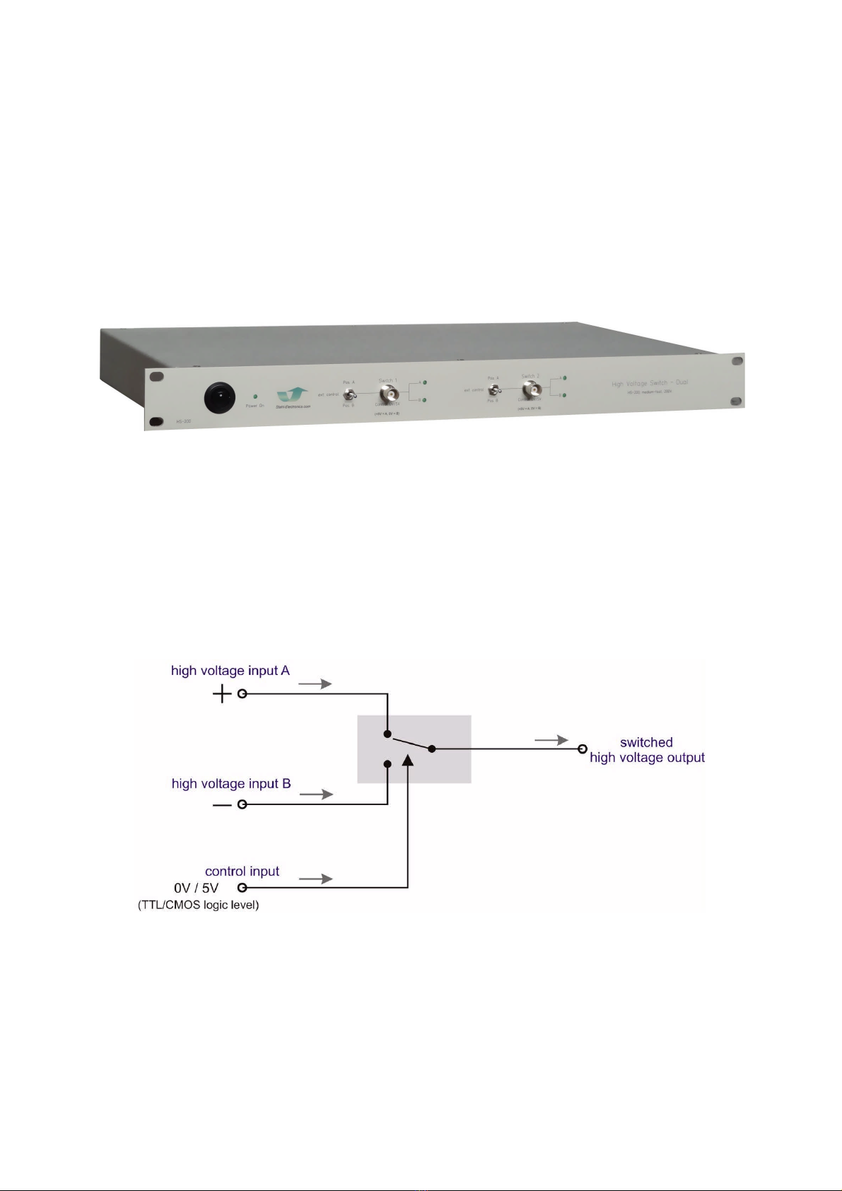
fig 2.1: front view of a HS-200 device (DUAL version)
2.2 Functional Principle and Block Diagram
The following scheme displays a block diagram of the internal structure and illustrates the functional
principle. The control input (BNC socket on front plate) defines the position of the internal high
voltage switch, which connects either input A or input B to the output. A digital signal (TTL/CMOS
level 0V/5V) may be applied to this control input at a rate between 0Hz (static operation) to 2kHz. A
three-position manual switch on the front side allows to override the digital control signal. The high
voltage switching elements inside the device are implemented as MOSFET-transistors, allowing fast
switching transitions in the order of 100ns and less.
fig 2.2: Block diagram of a HS-200 device. Inside the DUAL version, the scheme exists twice, i.e. there are two
independent switches.
Unlike high voltage pulse-generators the internal switch circuitry is implemented as fast static switch,
which means that the applied control input level defines the (static) switch position as illustrated in the
scheme above. The output is connected to the selected input by a (transistor based) resistor. The non-
selected input is isolated from the output by a high isolation resistance.

HS-Series Installation and User Manual, Rev 1.25
www.stahl-electronics.com phone: +49 6242-597-2140, fax: +49 32123 504884
5
Note that in standard version the applied input voltages at inputs A and B must obey a certain order:
voltage at input A always needs to be more positive than voltage at input B. For normal operation the
voltage difference (A-B) should not exceed +200V.
However, both input voltages may float up to +/-500V versus the case ground, which is an important
feature in many applications.
Bipolar Version
In the case that the order of input voltages (input A more positive than input B) can not be
permanently maintained, a bipolar version is also available. This version features internally two partial
switches in each signal branch, being able to serve positive as well as negative electrical currents.
fig 2.3: The bipolar version features two partial switches in each signal branch, thus can handle all
voltage polarities.
There are two disadvantages in this version, which are due to the altered internal circuitry:
first, the signal switching speed is slower (see also specification table), secondly the additional diodes
shown in 2.3 have the effect that the output voltage suffers from a drop of approximately 0.7V, thus
the bipolar device may be regarded as less precise as the non-bipolar version.
HS-Series Installation and User Manual, Rev 1.25
www.stahl-electronics.com phone: +49 6242-597-2140, fax: +49 32123 504884
6
Application example:
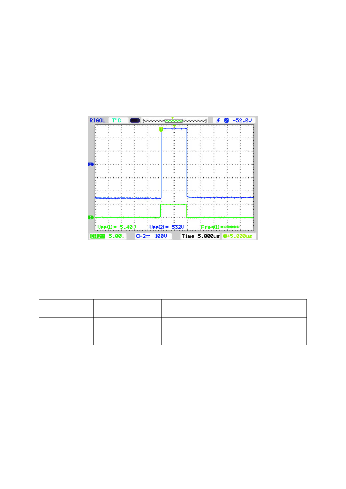
Generation of 10µs-duration positive 200Volt-pulse
The subsequent oscilloscope screen shot shows a typical application example. A control pulse of logic
levels (high = 5V, low = 0V) is applied to the control input. High voltage inputs A and B were
provided with an external voltage of 200V and 0V respectively. At the edges of the control signal the
switch is triggered, and switches from 0V to 200V (trace 1: 50V/div.) and after 10µs back to 0 Volt.
Trace 2 shows the control signal, being used to trigger the switch (trace 2: 5V/div.). A rectangular
pulse results with steep slopes and constant-voltage static levels.
fig 2.4: Oscilloscope screen shot of a positive 200V pulse, t = 10s duration.
The lower trace (trace 2) shows the digital control signal, trace 1 (upper trace) the output signal.
2.3. Device Variety
The following devices are currently members of the HS series device family:
HS-200 single or dual version
standard or bipolar version
Output voltages of maximum 200V span1)
HS-500 single or dual version
standard or bipolar version
Output voltages of maximum 500V span1)
HS-1000 single or dual version Output voltages of max. 1000V span1)
The devices with outputs up to 500V (vs. GND) are provided by default with BNC outputs at their rear
side, the other variants with higher voltages have SHV connectors. Voltages are referenced to case
ground.
Note 1): span is the maximum voltage difference between positive and negative inputs A and B.
HS-Series Installation and User Manual, Rev 1.25
www.stahl-electronics.com phone: +49 6242-597-2140, fax: +49 32123 504884
7
3. Installation
3.1. Mechanical and Electrical Installation
Positioning: Provide sufficient air cooling of the device and locate in normal horizontal position to
allow for defined air convection. Rack mounting into a standard 19” rack is as well possible as resting
the device on a table. If mounted in a rack, please make sure that all case vents are permanently
cleared in order to prevent overheating.
fig. 3.1: Keep air vents always cleared to ensure sufficient ventilation
Beware of external magnetic fields:
Strong external magnetic fields can impair, damage or even destroy this device (e.g. proximity to a
superconducting magnet). A maximum external field strength of no more than B = 5mT is admissible.
Not observing this important condition can lead to severe overheating of the device and increases the
hazard of fire.
Connecting to mains power:
Connect the device to the mains power supply (220 to 240V ac) by using an appropriate power cord,
being properly wired and providing a grounded outlet. The power cord must be suited with respect to
possible load currents and should be rated to 2A current.
Cabling of voltage outputs:
Always provide appropriate and safe cabling when connecting the device to other devices or
vacuum/experimental setups. Cabling is preferred using high voltage cable with proper shielding.
BNC or SHV connector cables are a suitable choice in order to ensure proper shielding against
external noise pickup and in order to provide protective ground for safety reasons. Always be aware
about the potential hazard of high electrical voltages to human beings and sensitive objects of all kind
(see also safety hints in section 1).
Please note that wiring may only be done when the device is turned off. Connecting a powered-
up output to external circuitry can easily cause sparks and electrical discharges. The resulting
overvoltages can severely and permanently damage the device itself and also external circuitry.
HS-Series Installation and User Manual, Rev 1.25
www.stahl-electronics.com phone: +49 6242-597-2140, fax: +49 32123 504884
8
4. Operation and Control Elements
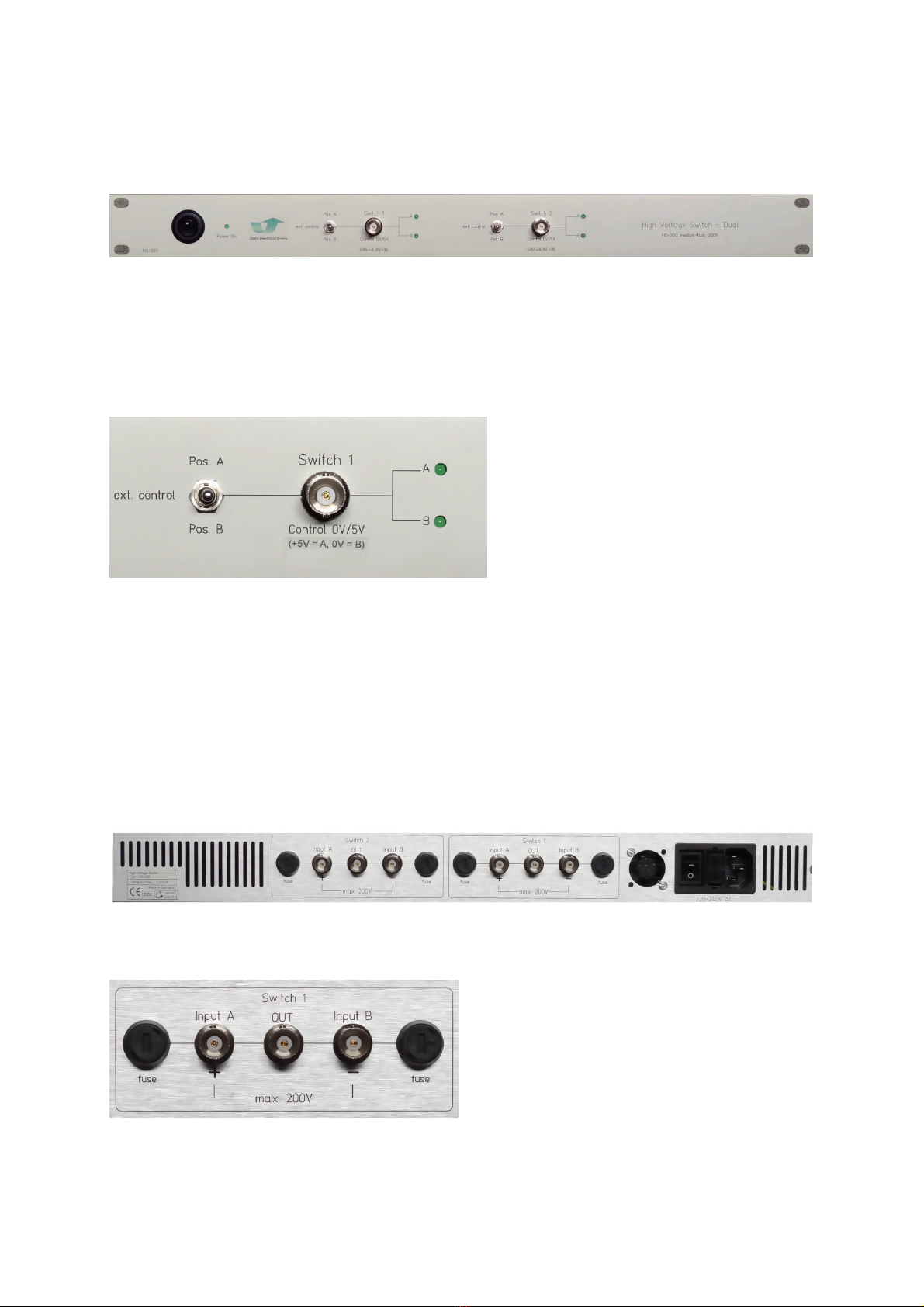
4.1 Elements on the front plate
mains supply Switch 1 Switch 2
switch BNC ext. / manual BNC ext. / manual
fig. 4.1: front plate elements
The front plate contains the control elements of the device. It is powered up after turning on the rear-
side mains supply switch and also the power button on the front plate. The Power-on-LED (green)
indicates proper operation of the internal circuitry.
fig. 4.2: manual switch, BNC input and LED indicators.
Each channel features a three-position manual switch (fig. 4.2). Lifted upwards, the output (rear side)
is connected to the high voltage input A, moved into lower position it connects the output to input B.
In the center position of this switch the control voltage, being applied to the BNC input, defines the
high voltage switch position. A high level connects the output with A, low level to B. Common 5V /
0V signal may be applied to this BNC control input. In practical cases a PC controlled Delay-Gate
generator or function generator is often connected to this BNC input. Switching rates up to 2kHz are
supported. The LED indicators on the right hand side show the switch status, indicating which input
(A or B) is connected to the output.
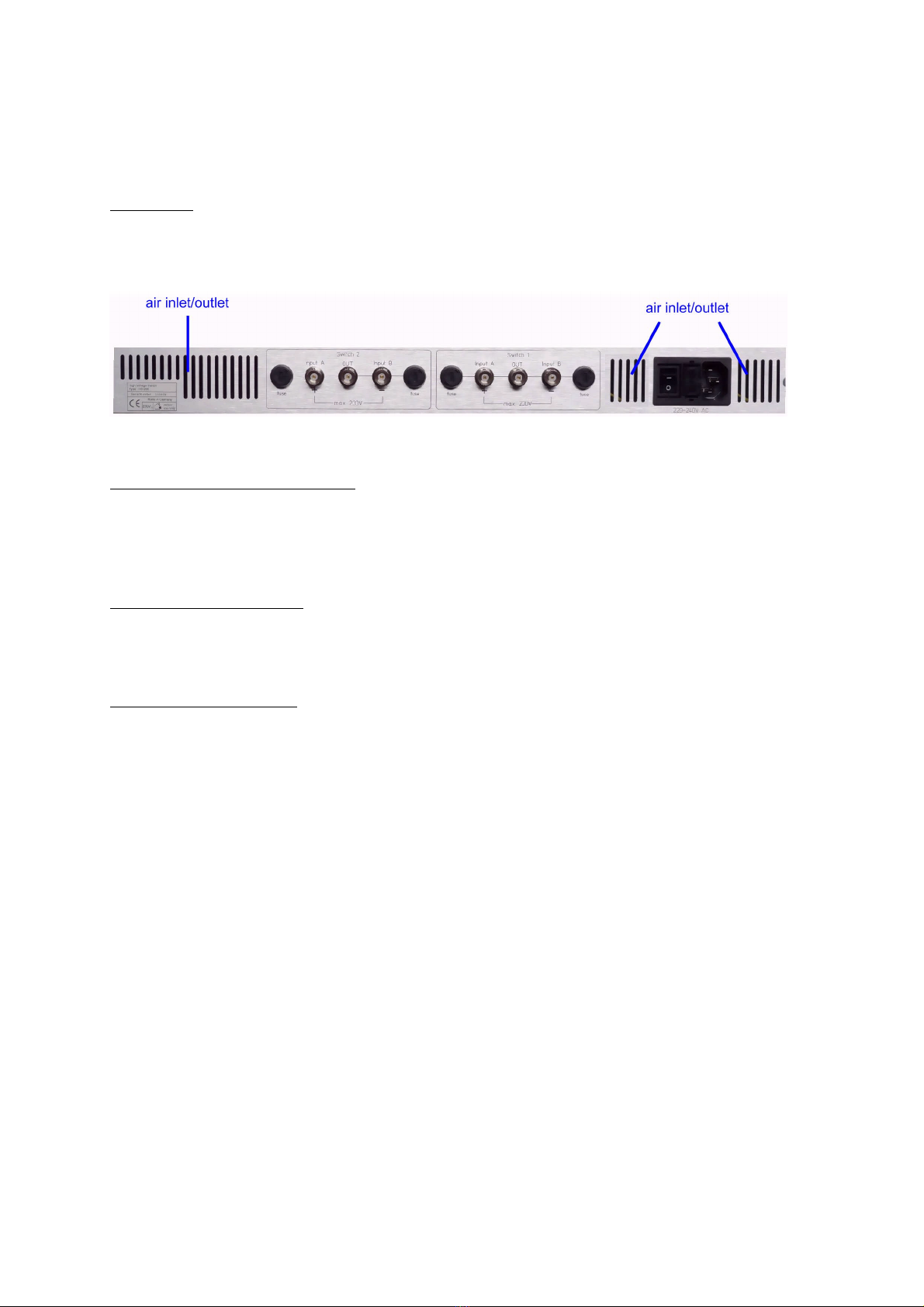
4.2 Elements on the rear side
fig. 4.3: rear side elements (a dual channel version is shown)
The rear side of the device contains the ventilation elements, 115V/230V supply connector, power
on/off switch (with fuses) and the high voltage inputs and outputs.
fig. 4.4: BNC sockets for at inputs and output
HS-Series Installation and User Manual, Rev 1.25
www.stahl-electronics.com phone: +49 6242-597-2140, fax: +49 32123 504884
9
Fig. 4.4 shows the BNC sockets for the two DC high voltage supply voltages A, and B and the switch
output OUT. Please note that the voltage on input A needs to be more positive compared to the voltage
on input B. This is indicated by the plus and minus sign “+” and “-“. In general, both input voltages
may reside in the range between -200V and +200V versus GND, but their difference should not
exceed 200V.
The fuse sockets shown in fig. 4.4 contain safety fuses for the two high voltage inputs. In case
extensive currents flow, they may blow. Nominal rating is 63mA, fast blow.
The inputs A and B can be connected to an appropriate high voltage supply, e.g. a device from the
stahl-electronics HV-series. The output is supposed to be connected to a switched electrode element or
ion trap. Please note that the capacitive load on this output may impair the switching speed
performance. Nominal loads from 0pF to 300pF may be connected. See also next section for
waveforms.
4.3 Output Characteristics
Dynamic Response
As soon as the internal switch connects either input A or B to the output, the latter assumes the voltage
on the respective input. There is a time constant related to each voltage transition, essentially given by
the internal switch resistance (approx. 140 ), the internal output current limit (approx. 1A) and the
capacitive load on the output, including all cables to an experimental setup. In case of connected BNC
cable, one may count about 100pF each meter cable length, therefor extensively long cables should be
avoided.
The following oscilloscope screen shots show voltage step transitions observed at the output with
small (17pF) and larger capacitive loads (250pF) for further illustration (applies for standard version,
not for the bipolar version, see also specifications table).
100V step
fig. 4.5 (left frame) positive voltage step of 100V (blue trace) with small capacitive load (C = 17pF) at the
output; (right frame) negative step of 100V with small capacitive load (C=17pF); transient rise time (10% to
90% of voltage step size) is in the order of 45ns in each case. The green trace shows the input trigger signal.

HS-Series Installation and User Manual, Rev 1.25
www.stahl-electronics.com phone: +49 6242-597-2140, fax: +49 32123 504884
10
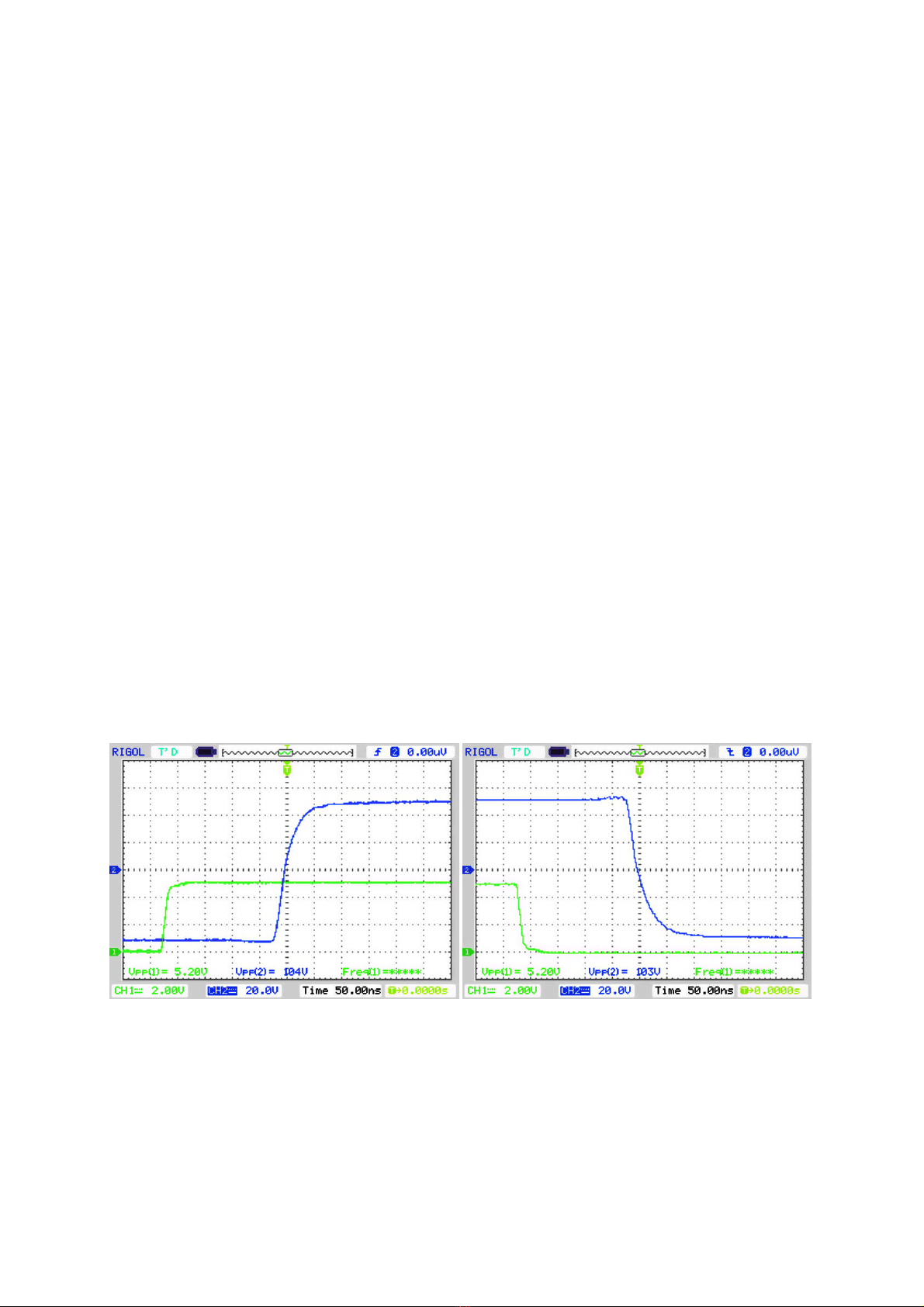
200V step
fig. 4.6 (left frame) positive voltage step of 200V (blue trace) with small capacitive load (C = 17pF) at the
output; (right frame) negative step of 200V with small capacitive load (C=17pF); transient rise time (10% to
90% of voltage step size) is in the order of 45ns in each case. The green trace shows the input trigger signal.
200V step with larger load
fig. 4.7 (left frame) positive voltage step of 200V (blue trace) with capacitive load of 250pF the output; (right
frame) negative step of 200V with same load; transient rise time (10% to 90% of voltage step size) is in the
order of 80ns in each case. The green trace shows the input trigger signal. The slower rise/fall times are mainly
caused by the internal safety current limit of approx. 1.1 Ampere
Noise and Ripple
In contrast to other devices, based on switched circuit / power switching technology, the HS series
devices feature a very low noise level. This makes them specially suited for ion traps, ion sources and
low energy beam line applications. Each output exhibits a very low broadband noise (DC to 20MHz)
of smaller than 350µVrms and a low ripple level (50Hz) smaller 50µVrms. In general the outputs are
completely free of parasitic switching spikes in the RF region.
HS-Series Installation and User Manual, Rev 1.25
www.stahl-electronics.com phone: +49 6242-597-2140, fax: +49 32123 504884
11
5. Maintenance
The HS series high voltage switches are designed for years of reliable operation. Under normal
operating conditions, they should not require electrical maintenance, except routine cleaning of dust.
Exchange of ventilation fan is strongly recommended every 50’000 operation hours (see below). If
any question should arise, please contact the manufacturer.
Routine cleaning
All ventilation openings should be checked periodically and kept free of dust and other obstructions. A
vacuum cleaner may be used to clean these vents when the unit is powered off. The front panel may be
cleaned periodically with a clean cloth and mild alcohol solution, when the unit is powered off. It is
recommended to send the device to the manufacturer routinely in 4-year intervals for internal cleaning
from dust.
Fan life time and temperature monitoring
The air ventilation fan is a part which shows unavoidable deterioration in time. Exchange of this part
is strongly recommended after 50´000 hours of operation. Please contact manufacturer for
replacement. Complete failure can lead to overheating of the device. Several temperature fuses and
other protection measures provide a certain degree of safety against fire hazard in this case.
Fire hazard
Please note, that excessive accumulation of dust inside the case of the device can lead to overheating.
This, together with possible discharges increases the risk of fire, caused by electrical sparks. Routinely
cleaning the device from dust minimizes this risk. It is therefore recommended to send the device to
the manufacturer routinely in 4-year intervals for internal cleaning from dust, or to have it cleaned by
an accordingly qualified electronical workshop. Also air conditions containing oil mists (e.g. in
proximity to a vacuum pump or mechanical machines) place a severe danger, since inflammable
substances could enter the device through the ventilation holes. If in doubt, cleaning by an accordingly
qualified electronical workshop or the manufacturer is strongly recommended.
An increased hazard of fire may also occur if the device has been (permanently or temporarily) located
in proximity to a strong (e.g. superconducting) magnet. A maximum external field of B = 5mT is
admissible.
6. Specifications
Control Input
typ. max. Conditions and remarks
required drive level 0V and 5V -2V to +6V
vs. GND
threshold 2.4V
input impedance 2k// 6pF
drive rate / switching rate 2kHz
Output Switch, static
static resistance
from A or B to OUT
“on”-state
145200IOUT < 200mA
isolation resistance from
A or B to OUT >10M
voltage differences from A or B to
OUT smaller or equal 200V
leakage currents from
A or B to OUT 40nA* 200nA*
voltage differences from A or B to
OUT smaller or equal 200V
HS-Series Installation and User Manual, Rev 1.25
www.stahl-electronics.com phone: +49 6242-597-2140, fax: +49 32123 504884
12
Parameter typ. max. Conditions and remarks
intrinsic switch capacitance
on OUT terminal
38pF approx. 85pF for bipolar version
Noise 350µVrms
admissible DC current
(continuous)
140mA
internal current limit,
shortly at switching instant
internal current limit,
permanent
1.1A
350mA
1.7A
Timing characteristics
a) standard version
delay from control input
change to output reaction 240ns 290ns
200V output step size
(positive or negative going)
delay jitter 0.4ns rms T = 25°C +/-1°C
max. pulse duration infinite
min. pulse duration 6.6µs
40ns capacitive load of 17pF (probehead)Output rise or fall time,
10% to 90% step size 80ns 100ns capacitive load of 250pF
b) bipolar version
delay from control input
change to output reaction
240ns 300ns 200V output step size
delay jitter 0.4ns rms
max. pulse duration infinite
min. pulse duration 6.6µs
80ns capacitive load of 17pF (probehead)Output rise or fall time,
10% to 90% step size 155ns 175ns capacitive load of 250pF
50ns capacitive load of 17pF (probehead)Output rise or fall time,
20% to 80% step size 93ns 105ns capacitive load of 250pF
Input Voltage Rating
Input A or B vs. GND +/-500V both polarities may be applied vs.
GND
Voltage difference
from A to B 200V
input A always needs to be on more
positive level with respect to B in
standard version, whereas polarity
does not matter in bopolar version
Fuse rating 63mA fast fuse replaceable on rear side
Environmental
Conditions
Magnetic Field max. 5 mT
Storage Temperature -55 C° to +85 C°
Operating Humidity &
Temperature
noncondensing relative humidity up to 95% between temperatures of
+10°C and +35°C.
Power Supply
AC input voltage 230VAC at 50Hz/60Hz or alternatively 110VAC.
The power entry module is EMI/RFI-filtered.
Fuse: medium fast blow 200mA
Power Consumption typ. 6W max. 9W
Case dimensions
19.00” wide x 10” deep x 1 height unit. Front-panel mounting holes are
configured for M6 rack configurations
weight approximately 1.2kg
Note *): Inputs A and B feature 1 Gresistors to ground for protection against parasitic charge up.
Currents through these protection resistors add to the numbers mentioned above.

HS-Series Installation and User Manual, Rev 1.25
www.stahl-electronics.com phone: +49 6242-597-2140, fax: +49 32123 504884
13
DECLARATION OF CONFORMITY
Manufacturer's Name: Dr. Stefan Stahl
- Electronics for Science and Research -
Manufacturer's Address: Kellerweg 23
67582 Mettenheim
Germany.
Declares, that the product
Product Name: HS series high voltage switch
Model Number: HS-200, HS-200 dual, HS-200 dual bipolar
Product Options: This declaration covers all options of the above product(s)
Conforms with the following European Directives:
The product herewith complies with the requirements of the:
1. Low Voltage Directive 73/73EEC;
2. EMC Directive 89/336/EEC (including 93/68/EEC) and carries the CE Marking
accordingly
Mettenheim, 26. Jan. 2017, Dr. Stefan Stahl, CEO
Table of contents
Other Stahl-electronics Switch manuals


Popular Switch manuals by other brands


NETGEAR
NETGEAR ProSAFE GS105v5 installation guide

socomec
socomec SIRCO PV manual

Endress+Hauser
Endress+Hauser Liquipoint T FTW32 operating instructions

NETGEAR
NETGEAR FS116P - ProSafe 16 Port 10/100 Desktop... installation guide

Siemens
Siemens CNFS Series operating instructions

Belden
Belden HIRSCHMANN EESX Series Hardware integration guide