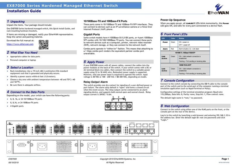
Relay Output Alarm
The switch provides one dry contact for signaling of
a user-defined power or port failure. The alarm
relay default is “open” and forms a closed circuit
when the event occurs. The relay output can be
connected to an alarm signaling device. Relay
output current is 30VDC / 0.6A.
NOTE: The initial normal state of the relay is open,
and if switch loses *all* power, then this state will
come into effect. This is important to remember
when using the relay to indicate a power failure.
The relay will close in an alarm state when there is
redundant power input and an alarmed input fails.
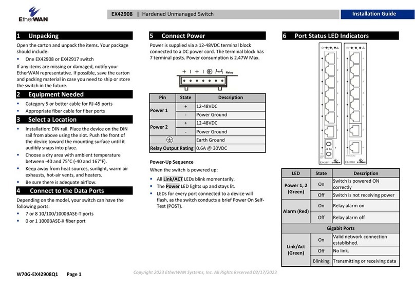
6 Front Panel LEDs
Link/Act
Green: Network connection established
Flashing: Port sending or receiving data
Red: Link down or power down
Reset Button: Press and hold for less than 10
seconds to reboot the switch. Press and hold for
more than 10 seconds to reset the switch to the
default password.
7 Initial Configuration
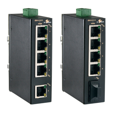
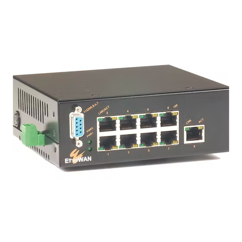
Connect to the switch using the enclosed Ethernet
cable to connect a serial port on a PC to the RJ-45
Management port located on the front panel next
to the USB port. You can also use regular Ethernet
cable to connect the RJ-45 port on the PC to any of
the TX ports 1 - 8. The IP address of VLAN 1 is
192.168.1.10.
Configuration via CLI
If using a terminal-emulation program such as Putty,
configuration settings are: Baud rate: 115,200bps,
Data bits: 8, Parity: none, Stop bit: 1, Flow control:
none.
The default login name is “root,” no password.
Configuration via Web Browser
Log in to the switch by launching a web browser
and entering 192.168.1.10 in the address bar.
Enter the default login ID: root (no password) and
click “Login.” The system information screen will
display.
8 Copy Configuration to USB
The USB port can be used to save the running
switch configuration to a (FAT32) USB storage
device. Plug the device into the USB port, and use
the “Save Configuration” command in the web
interface, or “copy running-config startup-config”
in the CLI.
