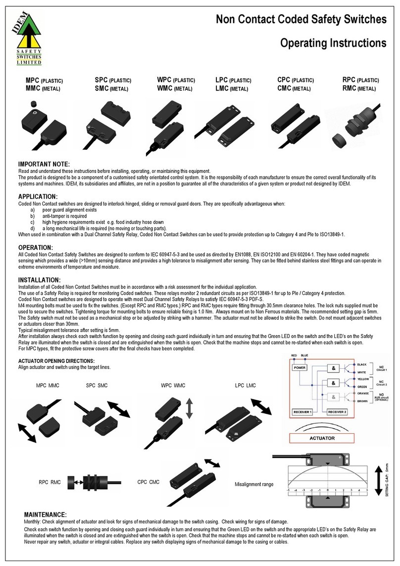
Idem UGB-NET-CS User manual

Operating Instructions
IDEM Safety Switches
UGB-NET-CS
102620 2210 UGB-NET-CS Operating Instructions Contents
1. Contents
2. System Overview .......................................................................................................................1
UGB-NET Switch Body.........................................................................................................1
3. Safety Functions ........................................................................................................................1
4. Installation & Maintenance .......................................................................................................2
Principle..............................................................................................................................2
Fastening ............................................................................................................................2
Maintenance Activities .......................................................................................................2
UGB-NET with Rotary Handle..............................................................................................3
UGB-NET with Sliding Handle..............................................................................................3
5. Electrical Connection .................................................................................................................4
6. Protocol Setup ...........................................................................................................................5
Network Address –Setup/Initial Setting.............................................................................6
Setting via DIP Switch .........................................................................................................6
Setting via DHCP .................................................................................................................6
Studio 5000 Ethernet/IP Configuration...............................................................................8
Factory reset.....................................................................................................................10
Functional Tests................................................................................................................10
7. Data Map.................................................................................................................................10
8. Diagnostic Indication ...............................................................................................................11
9. Technical..................................................................................................................................12
Device Characteristics.......................................................................................................12
Electrical Data...................................................................................................................12
Mechanical Data ...............................................................................................................12
Environmental Data ..........................................................................................................12
Reliability / Safety Data (EN ISO 13849-1).........................................................................12
Reliability / Safety Data (EN 62061 / IEC 61508)...............................................................12
NOTES.............................................................................................................................................13

Operating Instructions
IDEM Safety Switches
UGB-NET-CS
102620 2210 UGB-NET-CS Operating Instructions 1
2. System Overview
UGB-NET Switch Body
Key
1 –Pilot Devices
2 –Data Ports
3 –Power Ports
4 –Head End Entry
5 –Head Front Entry
6 –Manual Release
7 –Indication LEDs
8 –DIP Switch Cover
3. Safety Functions
IMPORTANT
•It is the responsibility of the user to ensure the correct overall functionality of its
systems and machines. IDEM its subsidiaries and affiliates are not in a position to
guarantee all of the characteristics of a given system or product not design by IDEM.
•All relevant safety regulations and standards are to be observed.
The UGB-NET-CS complies with the requirements of Cat. 4 / PL e and SIL 3 in accordance with ISO 13849-1,
IEC 62061 and IEC 61508. The device implements the following safety functions:
•Guard interlocking that complies with the requirements of IEC 60947-5-3 and is classified as a type 4
device with high coding in accordance with the application standard ISO 14119.
•Guard locking with lock monitoring for person protection.
•Emergency stop function (optional, see part number options)

Operating Instructions
IDEM Safety Switches
UGB-NET-CS
102620 2210 UGB-NET-CS Operating Instructions 2
4. Installation & Maintenance
Principle
The UGB-NET switch is mounted to the fixed frame of the guard or machine, the handle and actuator are
fitted to the moving guard with the actuator tongue aligned to the aperture of the switch head. The
mechanical tongue actuator profile is designed to match a cam mechanism within the switch head, the
cam and tongue together realise the specified holding force.
WARNING
DO NOT DEFEAT, TAMPER, OR BYPASS THE SAFETY FUNCTION.
FAILURE TO DO SO CAN RESULT IN DEATH OR SERIOUS INJURY.
NE PAS DESACTIVER, MODIFIER, RETIRER, OU CONTOURNER CETI, INTERVERROUILLAGE
IL PEUT EN RESULTER DES BLESSURES GRAVES DU PERSONNEL UTILISATEUR.
•Observe the county-specific regulations when installing the device.
•Repair or modification of the UGB-NET is not allowed unless authorised by IDEM
and carried out according to operating guidelines.
•Safety critical failures which do not lead to the safe state shall be reported to IDEM
immediately.
•Replace a malfunctioning UGB-NET immediately.
IMPORTANT
•Ensure that the static forces applied during normal operation do not exceed the
holding force (Fzh).
•Ensure that dynamic forces acting on the switch caused by bouncing of the guard do
not create an impact reaction force which exceeds the holding force (Fzh).
NOTES REGARDING :
•Maximum Temperature 40°C
Fastening
IMPORTANT
•If fitting rotary or sliding handles ensure the M6 mounting bolts are used to fix the
appropriate mounting plates.
•The tightening torque to ensure reliable fixing is 4.0Nm.
•The front and rear rotary handles can be adjusted for desired position by loosening
the locking bolt which fixes the handle to the switch body.
Maintenance Activities
IMPORTANT
•To achieve the target safety level, it is required to routinely check the safety
functions are operating correctly. For applications targeting PLe a check should take
place once per month, for PLd applications a check should take place once per year.
•If any part of the UGB-NET displays mechanical damage then remove and replace.
•IDEM will not accept responsibility for failure of the switch functions if the
installation and maintenance requirements shown in this document are not
implemented.

Operating Instructions
IDEM Safety Switches
UGB-NET-CS
102620 2210 UGB-NET-CS Operating Instructions 3
UGB-NET with Rotary Handle
Guard Front
Guard Rear
UGB-NET with Sliding Handle
Guard Front
Guard Rear

Operating Instructions
IDEM Safety Switches
UGB-NET-CS
102620 2210 UGB-NET-CS Operating Instructions 4
5. Electrical Connection
WARNING
•The device shall be supplied by a 24V SELV/PELV power supply acc. to IEC 61131-2
which limits the maximum voltage in case of failure to 60V.
•Function Earth must be connected.
NOTES REGARDING :
•To meet the requirements for UL a class 2 power supply must be used.
INFORMATION
•When multiple devices are used in a daisy-chain arrangement the power bus may be
forwarded via the UGB-NET device. Please see technical specification and ensure the
total current through each device does not exceed the specified maximum current.
INFORMATION
•Not all connections are required for all applications, the minimum requirement to
operate the device is one data connection and one power connection. All 4 ports are
utilised when the UGB-NET is used a ‘daisy chain’ configuration.

Operating Instructions
IDEM Safety Switches
UGB-NET-CS
102620 2210 UGB-NET-CS Operating Instructions 5
6. Protocol Setup
IMPORTANT
•The minimum time between the change of a single safe digital input and the
transmission to the CIP Safety is 32ms for the Interlock/Lock and Estop. In the case
of an input level change at both safe inputs at the same time the maximum safe
application reaction time is 42ms for Interlock/Lock and Estop.
•Clear any pre-existing configuration from any safety device before installing it onto a
safety network.
•Commission all safety devices with IP address prior to installing it onto a safety
network.
•When a SIL3 device is configured directly from a workstation, the user should
compare the transferred SCID and configuration data with the SCID and
configuration data originally viewed in the workstation.
•The configuration software shall assume an ASYNC parameter value of 1.
•Configuring an originator with connection data and/or target configuration data
must be downloaded to the target so it can be tested and verified. Only then can
SCIDs from the target be confirmed.
•Status-Bits reported by the device via CIP Safety messages shall not be used to
trigger the safety function of a device or system.
•The safety-related parts of the EDS (Electronic Data Sheet) of the UGB-NET-CIP
device shall not be altered.
•Each safety device shall have a single physical address that is unique on the devices
segment.
•The maximum operation time (proof-test interval) of the UGB-NET shall not exceed
20 years. When reaching the proof test interval, the UGB-NET shall be replaced and
put permanently out of order.
•After the detection of a safety critical error, the UGB-NET shall not be kept in fail-
safe state for more than 1 hour.
INFORMATION
•The device EDS file can be found via the UGB-NET product page of the IDEM
website www.idemsafety.com/products or alternatively please contact
technic[email protected]m

Operating Instructions
IDEM Safety Switches
UGB-NET-CS
102620 2210 UGB-NET-CS Operating Instructions 6
Network Address –Setup/Initial Setting
The UGB-NET IP address can be set via DHCP server or statically via the device DIP switches.
The UGB-NET in its out-of-the-box state will have DHCP enabled (All DIP switches OFF, no IP address set).
Setting via DIP Switch
To manually assign a static IP the DIP switches located on the lid of the UGB-NET are used. The following
steps can be performed with the device powered on or off, note the final step if the device is powered.
1. Locate the DIP switch cover on the UGB-NET body, remove the 2 cover screws and lift the DIP
switch cover to gain access to the DIP switches.
2. Using a small tool push the required switches to the ‘ON’ position to set the corresponding bit.
3. Cycle power to the UGB-NET or press and hold the reset button until the LEDs turn red then release to
reset the device. The UGB-NET will restart with the configured IP address and with DHCP disabled.
4. Replace the DIP switch cover and screws ensuring a tight seal to the switch housing.
INFORMATION
•The example given in the image above shows only switches 2, 16 and 64 set to
the ‘ON’ position. The resulting IP address is: 192.168.1.82
Setting via DHCP
1. Apply power to the UGB-NET, after a start-up period the ‘MS’ LED should be flashing green.
2. Using a PC station that is configured on the same network as the UGB-NET, run the BOOTP/DHCP tool.
3. Using the MAC address to identify the UGB-NET, select the UGB-NET in the ‘Discovery History’ window
and click ‘Add Relation’.

Operating Instructions
IDEM Safety Switches
UGB-NET-CS
102620 2210 UGB-NET-CS Operating Instructions 7
4. Configure the required IP address setting in the pop-up window and click OK.
5. Open an internet browser and type in the IP address of the UGB-NET.
6. Navigate to ‘Configuration’ under the ‘NETWORK’ menu.
7. Set DHCP to ‘Disabled’ and click ‘Save settings’
8. Cycle power to the UGB-NET or press and hold the reset button until the LEDs turn red then release to
reset the device. The UGB-NET will restart with the configured IP address and with DHCP disabled.

Operating Instructions
IDEM Safety Switches
UGB-NET-CS
102620 2210 UGB-NET-CS Operating Instructions 8
Studio 5000 Ethernet/IP Configuration
1. Download the EDS file for the UGB-NET and import to application control software.
2. Open or create a project with the PLC CPU, Partner and Ethernet/IP modules added.
3. Right click the Ethernet module and select ‘New Module…’
4. Find and select the UGB-NET-CIP (will only appear if EDS file imported correctly), click ‘Create’.

Operating Instructions
IDEM Safety Switches
UGB-NET-CS
102620 2210 UGB-NET-CS Operating Instructions 9
5. Set the device name (customisable –‘UGB_NET_CIP’ used as example only) and set the
previously configured IP address.
6. Change the Safety Network Number (SNN) to match that of the controller/PLC.
7. On the ‘Safety’ tab, uncheck the ‘Configuration Signature’ box, press OK.
8. The UGB-NET can now be utilised in the PLC program according to the UGB-NET data mapping.

Operating Instructions
IDEM Safety Switches
UGB-NET-CS
102620 2210 UGB-NET-CS Operating Instructions 10
Factory reset
Please consult the instruction manual of the application control software or for further assistance please
contact technical@idemsafety.com
Functional Tests
Once the device has been installed and setup within the EtherNet IP / CIP Safety application control
software the following checks are necessary to ensure correct operation of the system.
•Expected operation of all control circuits.
7. Data Map
See technical datasheet supplied with product. For assistance please contact:
technic[email protected]m

Operating Instructions
IDEM Safety Switches
UGB-NET-CS
102620 2210 UGB-NET-CS Operating Instructions 11
8. Diagnostic Indication
LED
Function
Colour
LS
Locking Switch Status
Red/Green
DS
Device Status
Red/Green
PS
Module Status
Red/Green
PN
Network Status
Red/Green
L1
Link 1
Amber/Green
L2
Link 2
Amber/Green
LED
LED State
Comment
LS
Off
Locking switch inactive, waiting for data connection
Green
Guard is closed and locked
Green flash
Guard is closed and unlocked
Red
Internal fault detected, reset required.
Red flash
Missing or incorrect RFID tag
Red double flash
Guard forced open, reset required.
Red/Green alternate
Reset in progress
DS
Green
Device running
Red
Internal fault detected
MS
Green
Connection to PLC, Run state
Green Flash
Connection to PLC, Idle state
Red
Major Fault
Red Flashing
Recoverable fault, check PLC/UGB-NET configuration
NS
Off
No IP address set
Green
Online, connection(s) established
Green flash 1Hz
Online, no connections established
Red
Network fault
Red flash
Connection timed out.
L1/L2
Off
No Ethernet link detected
Amber
Ethernet link detected
Amber flash
Ethernet data transfer
•Diagnostic LED’s are not reliable indicators and cannot be guaranteed to provide accurate
information. They should only be used for general diagnostics during commissioning or
troubleshooting. Do not attempt to use LEDs as operational indicators.

Operating Instructions
IDEM Safety Switches
UGB-NET-CS
102620 2210 UGB-NET-CS Operating Instructions 12
9. Technical
Device Characteristics
Actuator coding level
Type 4 (RFID), High (acc. to ISO 14119)
Assured sensing distance on (Sao)
10 mm
Assured sensing distance off (Sar)
20 mm
Assured locking distance
5 mm
Response time (E Stop)
36 ms max. (E-stop -> transmission to field bus)
Response time (Guard Interlock)
36 ms max. (Guard/Lock -> transmission to field bus)
Electrical Data
Operating voltage
24 V DC +10%/-15% (SELV/PELV)
Power Supply UL Requirements
Class 2 power supply must be used.
Current consumption, max.
600 mA (Lock solenoid enabled)
Allowed through current (daisy-chain)
5 A
Mechanical Data
Maximum holding force (F1)
3000 N
Rated holding force (Fzh)
2307 N
Body material
Die cast Aluminium
Head material
Stainless steel 316
Environmental Data
Operating temperature
-5 °C to 40 °C
Enclosure Protection
IP 65
Maximum operating altitude
2000 m
Shock and Vibration
Tested in accordance with:
IEC 60068-2-6 and IEC 60068-2-27
Pollution Degree (Storage and Operation)
Degree 2 (EN 60664)
Reliability / Safety Data (EN ISO 13849-1)
Category
4
Performance Level
e
MTTFd
High
DC
99%
Reliability / Safety Data (EN 62061 / IEC 61508)
Mission Time
20 years
SIL CL
SIL 3
PFHd (Guard Interlocking / Lock Monitoring)
7.3E-10
PFHd (Emergency Stop Function)
2.3E-9

Operating Instructions
IDEM Safety Switches
UGB-NET-CS
102620 2210 UGB-NET-CS Operating Instructions 13
NOTES

EC / EU Declaration of Conformity
MANUFACTURER:
EU REPRESENTITIVE:
ADDRESSES:
IDEM SAFETY SWITCHES LIMITED
IDEM SAFETY SWITCHES Ro SRL
Hindley Industrial Estate
Hindley Green
Bloc OD6, nr. 35
Wigan
Bulevardul Timișoara
Lancashire
București
WN2 4HR
061344
United Kingdom
Romania
DEVICE(s):
UGB-NET
THE LISTED DEVICES CONFORM TO THE ESSENTIAL HEALTH AND SAFETY REQUIREMENTS OF THE
FOLLOWING EUROPEAN DIRECTIVES AND STANDARDS
DIRECTIVES:
Machinery Directive
2006/42/EC
EMC Directive
2014/30/EU
STANDARDS:
EN 13849-1
:2015
EN 13849-2
:2012
EN 62061
:2015
EN 61508 (Parts 1-7)
:2010
EN ISO 14119
:2013
IEC 60947-5-3
:2013
THIRD PARTY APPROVALS:
TUV Rheinland Industrie Service GmbH
Am Grauen Stein
51105 Köln / Germany
(Notified Body for Machinery, NB 0035)
M.Mohtasham
Managing Director
Dec 2022
Other Idem Switch manuals
Popular Switch manuals by other brands
Matrix Switch Corporation
Matrix Switch Corporation MSC-2HD1624L product manual
Asco
Asco 7000 Series installation manual
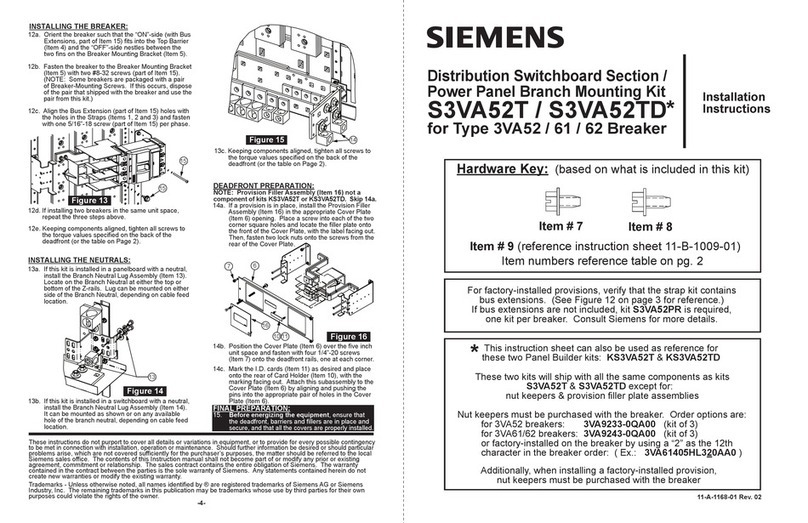
Siemens
Siemens S3VA52T installation instructions
TP-Link
TP-Link JetStream L2 Lite TL-SG3210 Cli reference guide
D-Link
D-Link DES-3225G Series user guide

HP
HP 5830AF-96G Series Disassembly instructions

