Stahlwerk MIG 200 User manual

STAHLWERK
MANUAL
MANUFACTURER: Shenzhen Stahlwerk Welding Technology Co., Ltd.
ADDRESS: 3F,Building 11, Heng Ming Zhu Science and Technology Park, Xin Qiao Tong Fu Yu
Indus rial Zone, Sha Jing S ree , Bao An Dis ric , ShenZhen Ci y
Tel:0755-23107730

·OWNER’S MANUAL· - 1 - SMC-003-A3
SAFETY WARNING
On the process of welding or cutting, there will be possibilit of injur , so please
take protection into consideration during operation. For more details please review
the Operator Safet Guide, which complies with the preventive requirements of the
manufacturer.
Electric shock——Ma lead to death !
Set the earth fitting according to app ying standard.
Forbidden to touch the bare e ectric parts and e ectrode with uncovered skin, wet g oves or
c othes.
Make sure you are insu ated from the ground and the work piece.
Make sure you are in safe position.
Gases and fumes——Ma be harmful to health!
Keep your head out of the gases and fumes.
When arc we ding, venti ators or air extractors shou d be used to avoid breathing gases.
Arc ra s——Harmful to our e es, burn our skin.
Wear suitab e protective mask, ight fi ter and protective garment to protect eyes and body.
Prepare suitab e protective mask or curtain to protect ooker-on.
Fire
We ding spark may cause fire, make sure there is no tinder stuff around the we ding area.
Noise——Excessive noises will be harmful to hearing .
Use ear protector or others means to protect ear.
Warn ooker-on that noise is harmfu to hearing.
Malfunction——When trouble happens, contact with authorized professionals
If troub e happens during insta ation and operation, p ease fo ow this manua instruction to check
up.
If you fai to fu y understand the manua , or fai to so ve the prob em with the instruction, you
shou d contact the supp iers or the service center for professiona he p.
When the se of the machine on an incline to prevent the machine overt rned.

·OWNER’S MANUAL· - 2 - SMC-003-A3
WARNING!
Creepage-protecting switch should be added when using the machine!!!
MACHINE DESCRIPTION
The we ding machine is a rectifier adopting the most advanced inverter techno ogy.
The deve opment of inverter gas-shie ded we ding equipment profits from the deve opment of the
inverter power supp y theory and components. Inverter gas-shie ded we ding power source uti izes
high-power component MOSFET to transfer 50/60Hz frequency up to 100KHz, then reduce the vo tage
and commutate, and output high-power vo tage via PWM techno ogy. Because of the great reduce of
the main transformer’s weight and vo ume; the efficiency increases by 30%. The appearance of inverter
we ding equipment is considered to be a revo ution for we ding industry.
CO2 shie ded we ding equipment adopts the most advanced inverter techno ogy by our. Inside of the
machine is equipped with e ectronic reactor circuit which can accurate y contro the process of the
e ectric short transition and b ending transition and resu t exce ent we ding characteristic. Comparing
with synergic we ding machine and other machine, it has the fo owing advantages: stab e wire speed,
compact, power saving, no e ectromagnetic noise. Continuous and stab e operation with sma current,
especia y suitab e for we ding sheet of ow-carbon stee , a oyed stee and stain ess stee . Automatic
vo tage pu sation compensation capabi ity, sma spark e, good arcing, uniform we ding poo , high duty
cyc e and so on.
The welding machine to meet the temperat re rise of 40 degrees ambient temperat re and rated
load cycle req irements.
The welding machine belongs to the CISPR11 first gro p eq ipment.
Thanks for purchasing product and hope for your precious advice. We wi dedicate to produce the best
products and offer the best service.
·OWNER’S MANUAL· - 3 - SMC-003-A3
WARNING!
The machine is mainl used in industr . It will produce radio wave, so the worker should
make full preparation for protection.
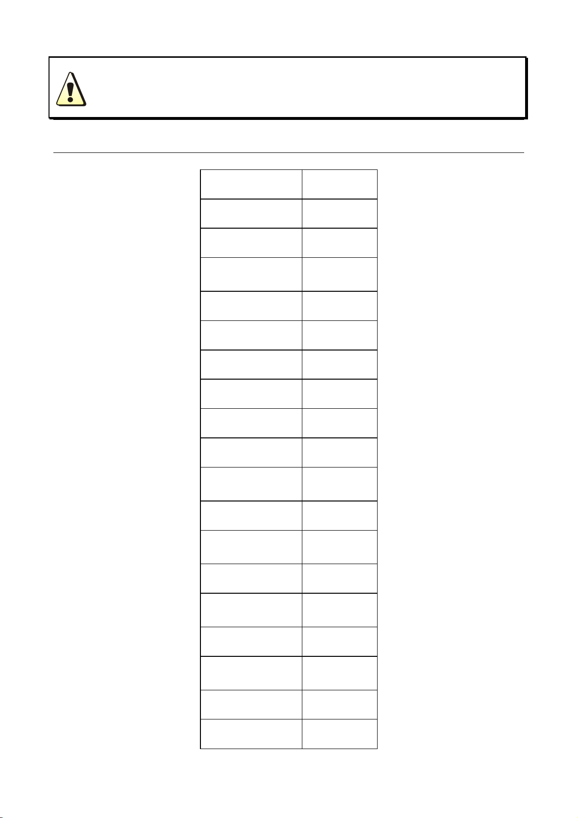
TECHNICAL PARAMETERS TABLE
Mode MIG 200
Power Vo .(V) 1 phase
AC230V±15%
Frequency(Hz) 50/60
Rated input current
(A) 37.4
Output current (A)
30-200
Output Vo . (V) 15.5-24
Duty cyc e(%) 60
Power factor 0.73
Efficiency(%) 80
Wire machine Compact
Wire speed(m /
min) 2.5-13
Post f ow (S) 1-10
wire whee diameter
(mm) 200
Wire diameter(mm)
0.6/0.8
Housing shie ding
grade IP21
Insu ation grade F
suitab e
thickness(mm) 0.8above
Weight (kg) 23.6
Dimension (mm)
610×330×540

·OWNER’S MANUAL· - 4 - SMC-003-A3
INSTALLATION INSTRUCTION
The we ding equipment is equipped with power vo tage compensation set. When power vo tage
f uctuates between±15% of rated vo tage, it sti works norma y.
When using ong cab e, in order to minimize the reduce of vo tage, big section cab e is suggested. If the
cab e is too ong, it wi affect the performance of arcing and other system function, so stated ength is
suggested.
1. Make sure the intake of the machine is not covered or b ocked to prevent the ma function of the
coo ing system.
2. Use earth cab e that the section no ess than 6mm2 to connect the housing and earth, the method is
from the connection in the back of the machine to the earth set, or make sure the earth end of
power switch reaches the earth. Both ways can be used for better security.
MIG 200Installation:
1) Connect the gas f ask with CO2 decompression f ow meter and the CO2 mouth behind the machine
via gas cab e.
2) Insert the swift p ug of earth cab e into the swift socket in the front pane .
3) Set the wire whee with wire on the whee axis, the
whee ho e shou d be matched with the whee fixer.
4) Choose wire s ot according to wire size.
5) Loosen the screw of wire-pressing whee , pit the wire
into so t via wire- ead tube, tune the wire-pressing
whee to fix wire from g iding, but pressure shou d be
suitab e in case the wire distorts and affects wire
sending.
6) Wire ro shou d turn c ockwise rotation to et out wire,
to prevent wire from g iding, wire is usua y set to the
fixed ho e on the whee side. To prevent the bent wire
from getting stuck, p ease cut off this part of the wire.
7) Put and tighten the torch on the output socket and put
the wire into the torch by hand.
Power supp y
(1 phase~230V)
MIG 200 Installation:

·OWNER’S MANUAL· - 5 - SMC-003-A3
OPERATION INSTRUCTION
1. Put the air switch to “ON” position, open the va ve of argon cy inder and adjust the f ow.
2. Adjust the wire diameter of the wire machine to rated number according to wire diameter.
3. Choose torch oopho e span based on wire diameter.
4. Tune the vo tage and speed knob to the right position based on the thickness of the work piece and
mechanics.
5. Press the torch switch to et out the wire to the torch head and begin to work.
MIG 200Compact CO2 Welding Machine Facial Sketch:
1 Current meter
2 Abnorma indicator
3 Power indicator
4 WIG/MIG/MMA switch
5 Wire diameter se ection
6 Gasafter f ow
7 Inductance adjustment
8 Positive output termina
9 Positive output termina
10 Negative output termina
11 Gas-e ectricity system output termina
12 Torch switch socket
13 Negative output termina
14 Power switch
15 Wire feeding speed adjustment
16 We ding vo tage adjustment

·OWNER’S MANUAL· - 6 - SMC-003-A3
NOTES OR PREVENTIVE MEASURES
1. Environment
1) The machine shou d be operated in dry environments with humidity eve s of max 90%.
2) Ambient temperature shou d be between -10 to 40 degrees centigrade.
3) Avoid we ding in sunshine or drippings. Do not et water infiter the machine.
4) Avoid we ding in dust area or the environment with corrosive gas.
5) Avoid gas we ding in the environment with strong airf ow.
2. Safet norms
The we ding machine is insta ed with protection circuit of over vo tage, over current and over heat.
When vo tage, output current and temperature of machine exceed the required standard, we ding
machine wi stop working automatica y. However, overuse (such as over vo tage) wi sti resu t in
damage to the we ding machine. To avoid this, the user must pay attention to the fo owing.
1) The working area is adequatel ventilated!
The we ding machine is powerfu machine, when it is being operated, it generated by high
currents, and natura wind wi not satisfy machine coo demands. So there is a fan in
inner-machine to coo down machine. Make sure the intake is not in b ock or covered, it is 0.3
meter from we ding machine to objects of environment. User shou d make sure the working
area is adequate y venti ated. It is important for the performance and the ongevity of the
machine.
2) Do not over load!
The operator shou d remember to watch the max duty current (Response to the se ected duty
cyc e). Keep we ding current is not exceed max duty cyc e current. Over- oad current wi
damage and burn up machine.
3) No over voltage!
Power vo tage can be found in diagram of main technica data. Automatic compensation
circuit of vo tage wi assure that we ding current keeps in a owab e range. If power vo tage is
exceeding a owab e range imited, it wi damage to components of machine. The operator
shou d understand this situation and take preventive measures.
4) There is a grounding screw behind we ding machine, with a grounding marker on it. Before
operation , we ding crust must be grounded re iab e with cab e which section is over 6 square
mi imeter, in order to prevent from static e ectricity , and accidents because of e ectricity
eaking.
5) If we ding time is exceeded duty cyc e imited, we ding machine wi stop working for protection.
Because machine is overheated, temperature contro switch is on “ON’’ position and the
indicator ight is red. In this situation, you don’t have to pu the p ug, in order to et the fan coo
the machine. When the indicator ight is off, and the temperature goes down to the standard
range, it can we d again.
·OWNER’S MANUAL· - 7 - SMC-003-A3
QUESTIONS TO BE RUN INTO DURING WELDING
Fittings, we ding materia s, environment factor, supp y powers maybe have something to do with
we ding. User must try to improve we ding environment.
A. Arcing-striking is difficult and eas to pause:
1) Make sure the earth cab e c incher connects the work piece we .
2) Check each connecting point connected or not.
B. Output current can not reach rated volume:
That supp ied vo tage is different from the rated wi ead to unconformity of the output current and the
adjusted current. When Supp ied vo tage ower than the rated, the max output current wi be ower than
the rated.
C. Current is not stabilizing when machine is been operating.
It has something with factors as fo owing.
1) E ectric wire net vo tage has been changed.
2) There is harmfu interference from e ectric wire net or other equipment.
D. Welding gap has air hole.
1) Check the gas supp y oop eaks or not..
2) Surface of mother materia has oi , stain, rust, acquer or other impurity.
MAINTENANCE
WARNING:
Before Maintenance and checking, power must be turned off, and before opening the
housing, make sure the power plug is pulled off..
1. Remove dust by dry and c ean compressed air regu ar y, if we ding machine is operating in
environment where is po uted with smokes and po ution air, the machine need remove dust every
month.
2. Pressure of compressed air must be within the reasonab e range in order to prevent damaging to
sma components of inner-machine.
3. Check interna circuit of we ding machine regu ar y and make sure the circuit connections are
connected correct y and tight y (especia y p ug-in connector and components). If sca e and rust are
found, p ease c ean it, and connect again tight y.
4. Prevent water and steam from entering into the machine. If that happens, p ease b ow it dry and
check insu ation of machine.
5. If we ding machine wi not be used for ong time, it must be put into the packing box and stored in
dry and c ean environment.
6. When wire machine operates for every 300 hours, the e ectric carbon brush and armature recitifier
shou d be added to the turbo and bearing.

·OWNER’S MANUAL· - 8 - SMC-003-A3
TROUBLESHOOTING AND FAULT FINDING
Notes: The fo owing operations must be performed by qua ified e ectricians with va id
certifications. Before maintenance,p ease contact with us for professiona suggestion.
Fault s mptom Remed
Power indicator is not it,
fan does not work and no
we ding output
1. Make sure air switch is c osed.
2. Check if e ectric wire net is in work.
3. Some of heat-variab e resistors(four) of power pane is damaged,
when it happen, genera DC24V re ay is open or connectors are poor
contact.
4. Power pane (bottom board) is damaged, DC 537V vo tage cannot be
output.
1) Si icon bridge is broken or connector of si icon bridge poor contact.
2) Power pane has been burned up.
3) Check contact and insert cab e from air switch to power pane are
poor contact, check contact and insert cab e from power pane to
MOS board are connected re iab y.
5. Auxi iary power of contro pane is in fau t.
Power indicator is it, fan
works, no we ding output
1. Check if a kinds of cab es of inter-machine are poor contact.
2. Output connector is cut off
3. Output connector is cut off or poor contacted.
4. Contro circuit is broken.
Power indicator is it, fan
works, abnorma indicator
is it.
1. Maybe it is overheated protection, p ease turn off machine first, then
turn on the machine again after abnorma indicator is off.
2. Maybe it is overheated protection, wait for 2-3 minutes.
3. Maybe inverter circuit is in fau t, p ease pu up the supp y power p ug
of main transformer which is on MOS board (VH-07 insert which is
near the fan) then open the machine again:
1) If abnorma indicator is sti it, some of fie distor of MOS board
are damaged, find out and rep ace them with same mode .
2) If abnorma indicator is not it:
a. Maybe transformer of midd e board is damaged, measure
inductance vo ume and Q vo ume of main transformer by
inductance bridge. If vo ume is too ow, p ease rep ace it.
b. Maybe secondary rectifier tube of transformer is damaged,
find out fau ts and rep ace rectifier tube with it.
If the machine fails to work normall after maintenance and check, please contact the local
dealer or after-sale service center.
·OWNER’S MANUAL· - 9 - SMC-003-A3
EARLIER CHECKING DIAGRAM FOR THE ABNORMAL
When abnorma situation such as fai ure of we ding, unstab e arc, poor we ding resu t, do not consider
that it must be some fau ts.
The machine may be we but just some reasons cause abnorma ity such as that some connectors are
oosened, forget to turn on the switch, wrong setting, broken cab e and gas pipe, etc. So before
maintenance, P ease check it up first, some prob em may be so ved.
The fo owing is ear ier checking diagram by this way. In the top right corner item you can find the
prob em, p ease check according to the diagram for the one with “O” mark.
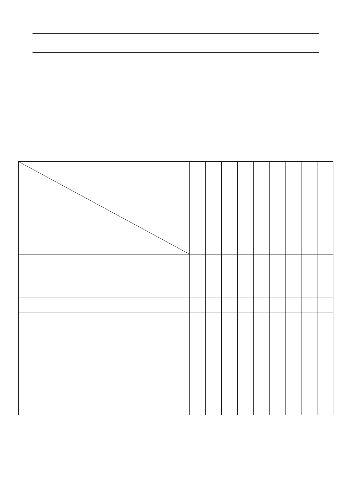
EARLIER CHECKING DIAGRAM FOR THE ABNORMAL
The abnorma
P ace and item to be checked
No arcing
No gas
Can not Send wire
wire
Poor Arcing initiation
Unstab e arc
We ding margin unc ean
Wire and Materia
cong utinated
Wire inks E ectric eading ho e
fcon cong utinated
Have air ho e
Power supp y(input
protective set )
1. Connected or not
2. Fuse broken
3. Connector oosen
〇 〇 〇 〇 〇 〇
Input cab e
1. Broken or not
2. Connector oosen
3. Overheat
〇 〇 〇 〇 〇 〇
Power 1. Switched or not
2. Lack phase 〇 〇 〇 〇 〇 〇 〇 〇
Gas cy inder & adjuster
1. Open cover
2. Remains of gas
3. F ow setting vo ume
4. Connecting point oosen
〇 〇
Gas pipe (access from the
high-pressure cy inder to
torch)
1. Connecting point oosen
2. Pipe broken 〇
Wire sending equipment
1. Whee and eading tube
not match
2. Whee broken, s ot b ocked
or ack
3. Over pressing or oosen,
powder store up in
entrance of SUS tube
〇 〇 〇 〇 〇

·OWNER’S MANUAL· - 10 - SMC-003-A3
EARLIER CHECKING DIAGRAM FOR THE ABNORMAL
WARNING:If not necessar , before checking the power suppl box must be cut off to
insure securit . Violating the above principle, it will lead to serious accident
threatening life safet like electric shock and burning
EARLIER CHECKING DIAGRAM FOR THE ABNORMAL
The abnorma
P ace and item to be checked
No arcing
No gas
Can Not sending wire
Sen
d wire
Poor Arcing intiation
initiation
Unstab e arc
We ding margin unc ean
Wire and
Materia cong utinated
Wire inks
E ectric eading ho e
Have air ho e
Torch and cab e
1. Cab e over winding and over
bending
2. Adaptabi ity of e ectric ho e, wire
sending tube and the wire size
〇 〇 〇 〇
Torch body
1. E ectric ho e, oopho e, oopho e
connector oosen.
2. P ug of torch not fixed
〇 〇
Torch power cab e and
switch contro cab e
1. Broken (over bending)
2. Damaged by heavy stuff 〇 〇 〇 〇 〇
Main materia
surface
1. Oi , stain, rust, acquer fi m
2. Wire come out too ong 〇 〇 〇 〇 〇
Output cab e
1. Cab e section is not big enough
2. (+)、(-)connecting points of
output cab e oosen
3. Poor e ectric eading abi ity of
main materia .
〇 〇 〇
Lengthened cab e
1. Cab e section is not big
enough
2. Winding and bending
〇 〇 〇 〇
We ding operation
condition
Confirm the we ding current, vo tage,
torch ang e, we ding speed, and
extended wire ength
〇 〇 〇 〇 〇
·OWNER’S MANUAL· - 11 - SMC-003-A3
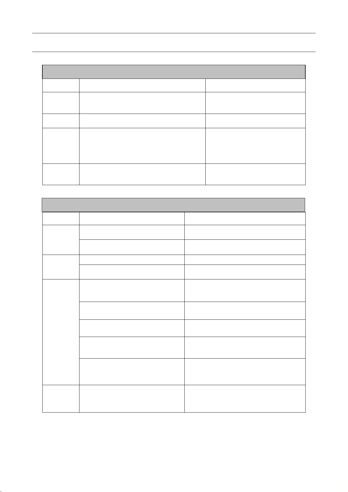
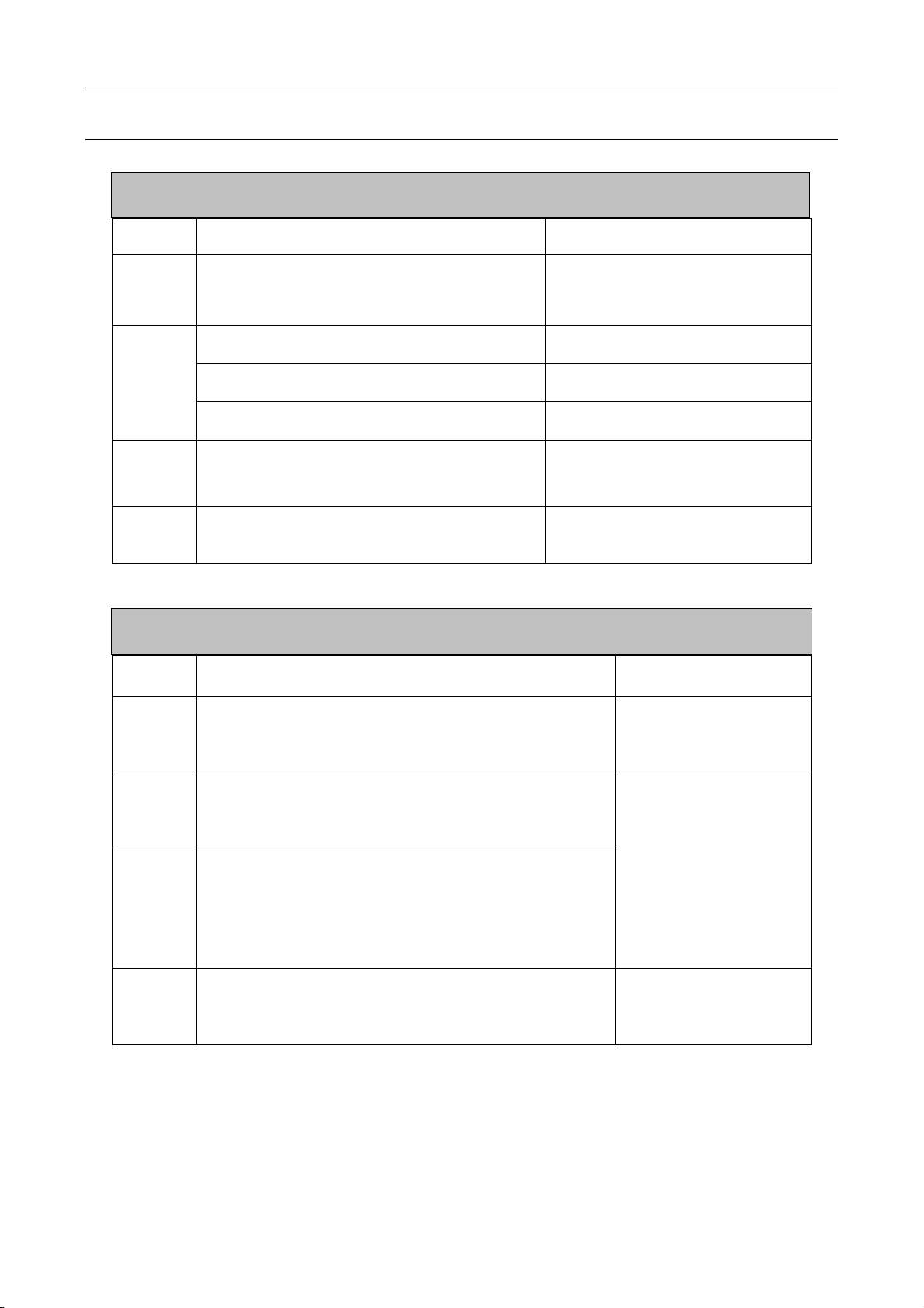
DAILY CHECKING
Position Checking keys Remarks
Contro
pane
1. Switch condition of operation, transfer
and insta ation.
2. Test the power indicator.
Coo ing
fan
1. Check if there is wind and the sound
norma or not.
If abnorma noise and no wind, to
check the inner.
Power part
1. When e ectrified, abnorma sme or not.
2. When e ectrified, abnorma vibration and
buzz or not.
3. Co or changing and heating or not in
appearance.
Periphery
1. Gas pipe broken, oosen or not.
2. Housing and other fixed parts oosen or
not.
Position Checking keys Remarks
Loopho e
1. If insta ment fixed, the front
distorted Reason for air ho e.
2. Attach sp ash or not. Reason for burning the torch.
(can use sp ash-proof materia )
E ectric
ho e
1. If insta ment fixed Reason of torch screw thread damage
2. Damage of its head and ho e
b ocked nor not Reason of unstab e arc and broken arc
Wire
sending
tube
1. Check the extended size of the
pipe
Have to be changed when ess than 6mm,
when the extended part too sma , the arc
wi be unstab e.
2. Wire diameter and the tube inner
diameter match or not
Reason of unstab e arc, p ease use the
suitab e tube.
3. Partia winding and extended Reason of poor wires sending and
unstab e arc, p ease change.
4. B ock caused by dirt in the tube,
and the remains of the wire
p ating ay.
Reason of poor wire sending and
unstab e arc, (use kerosene to wipe or
change new one.)
5. Wire sending tube broken O
circ e wear out
1.Pyrocondensation tube broken, change
new tube
2.Change new O circ e
Gas
bypass
Forget to insert or the ho e b ocked,
or different factory component.
May ead to vice (sp ash) because of poor
gas shie d, torch body get burned (arc in
the torch), p ease hand e.
WELDING TORCH
WELDING POWER SUPPLY
·OWNER’S MANUAL· - 12 - SMC-003-A3
DAILY CHECKING
Position Checking keys Remarks
Pressing
arm
1. If put the arm to the suitab e indicating
eve .(notes:not to damage wire ess than
Ф1.2mm )
Lead to unstab e arc and wire
sending.
Wire
ead
tube
1. If powder or residue store up in the mouth
of the tube.
C ean the residue and check the
reason and so ve it.
2. Wire diameter and the tube inner diameter
match or not
If not match, ead to unstab e arc
and residue.
3. If the tube mouth center matches the wire
whee s ot center or not.
If unmatched, ead to unstab e arc
and residue.
Wire
whee
1. Wire diameter matches the whee ’s
requirement
2. If the whee s ot b ocked.
1. Lead to unstab e arc and
residue, and b ock wire tube.
2. Change new one of necessary.
Pressure
whee
Check the stabi ity of its move, and
wearing-out of pressed wire, the narrowing of
its contact surface
Lead to unstab e arc and wire
sending.
Position Checking keys Remarks
Torch
cab e
1. If torch cab e over bended.
2. If the meta connecting point of mobi e p ug oosen.
1. Cause poor wire
sending.
2. Unstab e arc if cab e
over bended.
Output
cab e
1. Wearing-out of the cab e insu ated materia .
2. Cab e connecting head naked(insu ation damage),or
oosen(the end of power supp y, and cab e of main
materia connecting point.)
For ife security and
stab e we ding, adopt
suitab e method to
check according to
working p ace.
Simp e check dai y
Carefu and
in-depth check on
fixed period
Input
cab e
1. If the connect of power supp y input, protective
equipment input and the output end fixed or not.
2. If the security equipment cab e re iab y connected.
3. If the power input end cab e fixed.
4. If the input cab e is worn out and bares the
conductor.
Earth
cab e
1. If the earth cab e that connects the power supp y is
broken and connect tight y.
2. If the earth cab e that connects the main part is
broken and connects tight y.
To prevent creep age
and insure security,
p ease make dai y
check.
CABLE
WIRE SENDING MACHINE
Table of contents
Other Stahlwerk Welding System manuals


