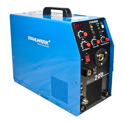
Stahlwerk AC/DC WIG241P User manual

1
VECTOR DIGITAL
MANUAL
Digital seriers—
AC/DC WIG241P
ENG ver. 1.3 2013-03-23

2
MANUFACTURER: Shenzhen Stahlwerk Welding Technology Co., Ltd.
ADDRESS: 3F,Building 11, Heng Ming Zhu Science and Technology Park, Xin Qiao Tong Fu Yu Indus rial Zone, Sha Jing S ree , Bao An Dis ric ,
ShenZhen Ci y
Tel:0755-23107730
SWEDEN authorized distributor: Stahlwerk - SW S etsteknik AB
Postadress: Hästho sstigen 1, 296 34 ÅHUS, SWEDEN
Lager och le eranser: Boställsgatan 6, 28832 VINSLÖV, SWEDEN
Tel: 044-2531310 (mån-tor 10-17, torsdag 13-17, fre-sön 10-16, lunch normalt 12-13)
E-Mail: info@stahlwerk.se,
Internet: www.stahlwerk.se
CONTENTS
1. Contents ....................................................................... 2
2. Specifications .................................................................... 3
3. Power Source Controls Indicators And Features .... 4
4. Introduction For The Machine ....................................... 6
5. Operation ............................................................................ 8
6. uestion Of The Welding Technology ........................ 8
7. Power Souce Problems ................................................... 9

3
OPERATION AND ATTENTION
Specifications
Model
Parameters AC/ C WIG-241P
Input voltage(V,Hz) AC230±15%, 50/60
Input power capacity(KVA) 7.2
No-load loss(W) 40
uty cycle(%) 25
Power factor 0.93
Efficiency(%) 80
Insulation class F
Protection IP21
Accessories Weight(Kg) 6.5
Machine weight (Kg) 23
imension(mm) 630x380x520
Tig-welding Arc-welding
Input current(A) 20.7 32.2
Rate output current(A) 200 200
Currentadjustment range(A) 10-200 10-200
No-load voltage(V) 67 67
Work voltage(V) 18 28
Inter-diameter of burner(mm) -- --
Air compress (Mpa) -- --
Gas flow(L/min) 2-5 --
Thickness(mm) -- --
Arc polite model HFoscillate/ Touch Touch

4
OPERATION AND ATTENTION
9.01 Power Source Controls ,Indicators and Features
2 T
4 T
MM A
W IG
A C
H F
C
A
V
S H z
A C F re q ue n z S tr o mv e rl ag e ru n g
A C / D C W I G 2 1 P4
R e m o t e
%
A R C H o ts ta rt
A R C S ta rt ze it
A R C S pr h li c ht b og e nü
G a s vo r la u f
St a r ts tr o m
St r o m a n s t i e g
Sc h we i s tr o m
β
Im pu l s
Im p u l s
Im p u l s fr e q ue n z
St r o m a b s e n k u ng
Sc h l u s t r o m
β
G a s na c h la u f
st ro m
w e i te
R E S J O B
S AV E
1
2
3
4
5
6
7
8
1 0
11
12
13
14
15
16
17
18
19
2 0
21
22
2 4
23
26
25
27
28
2 9
30 3 1
3 2 3 3 3 4 3 5
1 RESET button
2 Pulse indicator
3 Pulse button
4 2T indicator
5 4T indicator
6 2T/4T Cycle choose button
7 MMA indicator
8 WIG indicator
** ******************************************
10 MMA/WIG Cycle choose button
11 Current meter
12 Voltage meter
13 Current Unit indicator
14 Time Unit indicator
15 uty cycle unit indicator
16 Frequency unit indicator
17 Power indicator
18 Over-current/Over-heat indicator
19 JOB model indicator
20 JOB model button
21 SAVE indicator
22 SAVE button
23 HF indicator
24 HF button(Only WIG)
25 AC indicator
26 C indicator
27 AC/ C botton(AC Only WIG)
28 Reduce parameter button
29 Increase parameter button
30/31 Function selection button
32 Negative output terminal
33 Torch switch socket
34 Argon/air output terminal
35 Positive output terminal

5
OPERATION AND ATTENTION
9.02 Power Source Controls ,Indicators and Features
AC Frequenz StromverlagerungRemote
ARC Hotstart
ARC Startzeit
ARC Spr hlichtbogenü
Gasvorlauf
Startstrom
Strom a nstie g
Schwei strom
β
Impuls
Impuls
Impulsfreq uenz
Strom a bsenkung
Schlu strom
β
Gasnachlauf
strom
we ite
3 7 38 39 4 1 4 3 4 4 45 4 6
42
40
5 2
5 1
50
48
47
4 9
37 Pre-flow indicator 45 End current indicator
38 Start current indicator 46 Post flow indicator
39 Up-slope indicator 47 Hot start indicator
40 uty cycle indicator 48 Hot start time indicator
41 Peak current indicator 49 Arc force current indicator
42 Pulse frequency indicator 50 Clean area indicator
43 Basic current indicator 51 Remote control indicator
44 own slope indicator 52 AC Frequency indicator

6
OPERATION AND ATTENTION
9.03 INTRODUCTION
AC/ C WIG241P have sticking and AC/ C wig
welding,PULSE/ C wig welding many functions,
which adopt the most advanced inverter technolo-
gy.
The development of inverter gas-shielded welding
equipment profits from the development of the
inverter power supply theory and components.
Inverter gas-shielded welding power source utilizes
high-power component MOSFET/IGBT to transfer
50/60HZ frequency up to 100KHz/40KHz, then
reduce the voltage and commutate, and output
high-power voltage via PWM technology. Because
of the great reduce of the main transformer’s
weight and volume; the efficiency increases by
30%. The appearance of inverter welding
equipment is considered to be a revolution for
welding industry.
The welding power source can offer stronger, more
concentrated and more stable arc. When stick and
work piece get short, its response will be quicker. It
means that it is easier to design into welding
machine with different dynamic characteristics, and
it even can be adjusted for specialty to make arc
softer or harder.
As sticking and arc welding ,outer characteristic of
welding machine is constant current .Welding curr
ent will not be changed with arc length and current
is stable very much .As plasma cutting ,after arc
has pressed forcedly by air which is flowing
rapidly ,temperature is rise to 10000-15000℃ and it
is up to high coinable situation then strong plasma
arc has been formed .Cutting metal rapidly with
plasma arc, heat is concentrated and energy is
used effectively and smooth cutting section can be
got.
AC/ C WIG241P can be used in welding and
cutting of mild steel, stainless steel, alloy steel,
copper and other color metal .It has lightness, high
efficiency, energy-saving, stabilizing and reliable,
The welding machine to meet the temperature rise
of 40 degrees ambient temperature and rated load
cycle requirements.
The welding machine belongs to the CISPR11 first
group equipment.
Welcome to purchase products of our company
and make suggestions, we will try our best to
perfect our products and service.
Various functional options
1. When use MMA(ARC)function.
1) Make sure the cable, holder and fastening
plug have been connected with the ground. Put the
fastening plug into the fastening socket at the
“-“ terminal and fasten it clockwise.
2) Put the fastening plug of the cable to fastening
socket of “+” terminal at the front panel,fasten it
clockwise,and the earth clamp at the of the terminal
clamps the work piece.
3) Please paty attention to the connecting
terminal , C welding machine has two connecting
ways: positive connection and negative
connection.Positive connection:holder connects with
“-”terminal ,while work piece with the “+” terminal.
Negative connection:work piece with the “-”terminal.
Choose suitable way according to working situation.If
unsuitable choice is made,it will cause unstable arc
more spatters and conglutination,If such problems
occurs,problems occur,please chang the polarity.of the
fastening plug.
2. When use TIG function.
4) Connect well the protecting gas source,Gas
supply passage includes cylinder,argon meter and gas
pipe.The joint part of the pipe should be tighten by
hoop or other things in order to prevent leakaged and
air from coming in.
5) Install the air-electricity system plug to the
socket in the panel and fix it clockwise .Air plug of the
cutting torch and arc-keepingcable should be
connected to relevant socket,and fix the screw.
6) Put the loop cable plug to the fastening
socket,and tighten clockwise ,another terminal holds
the work piece.

7
OPERATION AND ATTENTION
2T
4T
MMA
W I G
PLASMA
AC
H F
C
A
V
SH z
AC F r eq u e nz S tro m v e rla g e ru n g
A C / D C P L A S M A W I G 2 5 1 P
R e m o t e
%
AR C H o t sta r t
AR C S t ar tz e it
AR C S p r hli ch tb o g e nü
Ga s v o rl a u f
Sta r tst r o m
Str o ma n s tie g
Sc h w e i s tr o m
β
Im pu l s
Im pu ls
Im pu l sfr e q ue n z
Str o ma b s en k un g
Sch l u s tr o m
β
Ga s n ac h la u f
str o m
we it e
R E S JO B
S AV E
Connect
grounding
Handle
Power supply
2 0v
3
Gas
Cylinder
earth clamp
Work piece
TIG torch
WIG/MMA installation
Electroed holder

8
OPERATION AND ATTENTION
9.04 OPERATION
1 . TIG welding function
1) Turn on the power switch at the back panel,
digital current meter is normal, fan begins to wheel.
2) Open the valve of argon cylinder , adjust the
volume of flow meter and make it is adequate to
welding .
3) Press switch of torch, electromagnetic valve
is started. Sound of HF arc striking can be heard
when HF wig state, at the same time argon is
flowing from torch burner. NOTES: When welding
is first operated, user must press switch of torch
several seconds and begin to weld until all of air is
be drained out. When welding is over, argon will
still flow out in several seconds in order to protect
welding spot before cooled down .So torch must be
kept welding place some time before arc has been
extinguished.
4)According to the workpiece need to set the
corresponding working state (AC or C,PULSE or
C)and suitable welding current and make sure
welding current is adequate to thickness of work
piece and process demand.
5)It is 1-4 mm from welding tungsten electrode
to work piece, press control knob of torch ,burn and
strike arc , sound of HF arc-striking will be
diminished .The welding machine can be operated
now.
2. MMA(ARC)function
1) Open power switch of front panel, fan begins
to work.
2) Make sure function switch of front panel is on
“down” position that is sticking. Impulse
changeover switch and knob of current down-slope
time will not work.
3) Make sure welding current is adequate to
thickness of work piece.
9.05 UESTION
Please refer to the WIG or PLASMA machine
manul.
CAUTION
Please don’t switch the function keys when the ma-
chine is in use.

9
PROBLEMS/SERVICE
9.06 Power Source Problems
NOTE
If user wants to operate machine as following, the operator must be a personnel in a specific field of electricity
and safety and hold the relevant certificate that proves there ability and knowledge. Before maintenance,
contact with our company for authorization is suggested.
Faults Resolvable Methods
1.Power indicator is not lit,
fan is not working, there is
no welding output.
1. Power switch is damaged.
2. Make sure electrify wire net, which is connected to input cable is working.
3. Make sure if input cable is broken circuit.
2.Indicator of power switch
is lit, fan is not working or
revolves several circles
and stopped, there is no
welding output.
4. Fuse is broken.
5. Short voltage protection is starting.
6. Cable, which is from switch to power panel, is loosed, tighten it again.
7. 24Vrelay of main return circuit of power panel is not close or damaged, check
24V power and relay .If relay is damage, replace it with some model.
3.Fan is working, abnorm-
al indicator is not on, sou-
nd of HF arc striking can be
heard, wipe arc welding
cannot strike arc.
8. Measure voltage of positive and negative electrode is about C308v from power
panel to VH insert.
a) If it is broken circuit and insert cable of Silicon Bridge is poor contact.
b) If one of four high electrolytic (about 470UF/450V) of power panel is
leaking, replace it.
9. Assistant power source supply power abnormally, normal voltage is C 24V.
10. Check if all kinds of connect and insert cable is poor contact.
11. Check if there is some question in control circuit, connect with seller. If control
cable of torch is broken.
4.Abnormal indicator is not
lit, sound of HF arc striking
can be heard, wiping arc
welding can strike arc.
12. Cable of torch is broken.
13. Grounding cable is broken or is not connected to work piece.
14. Output terminal of positive electrode or there is loose between electrify output
terminal of torch and inter-machine.
5.Abnormal indicator is not
lit, sound of HF arc striking
can be heard, and there is
no welding and cutting
output.
15. Primary cable of arc-striking transformer is poor contact with power panel,
tighten it again.
16. Arc-striking tip is oxidized or distance is too far, give a good polish oxide of
burner or adjust it is 1 mm between burners.
17. Changeover switch of sticking/arc welding is damaged, replace it.
18. Some of components of HF arc striking check and replace it.

10
6.Abnormal indicator is on, there is no output.
19. Maybe it is over current protection, please close
machine first, then open the machine again after abnormal
indicator is out of work.
20. Maybe it is overheated protection, wait for 2-3 minutes
(argon-arc welding does not has overheated protection
function.) and machine can be operated normal.
21. Maybe inverter circuit is fault, Please check whether
the IGBT/FR is damaged or not.
22. Maybe feedback circuit is opened.
7. henwelding aluminum,can not break oxidized
film
23. Wrong welding value
24. Pulse duty too low
25.Twice inverter MOSFET broken
If after checking and adjustment it still can not work normally, please contact the local distributor or our service
center.
Table of contents
Other Stahlwerk Welding System manuals
