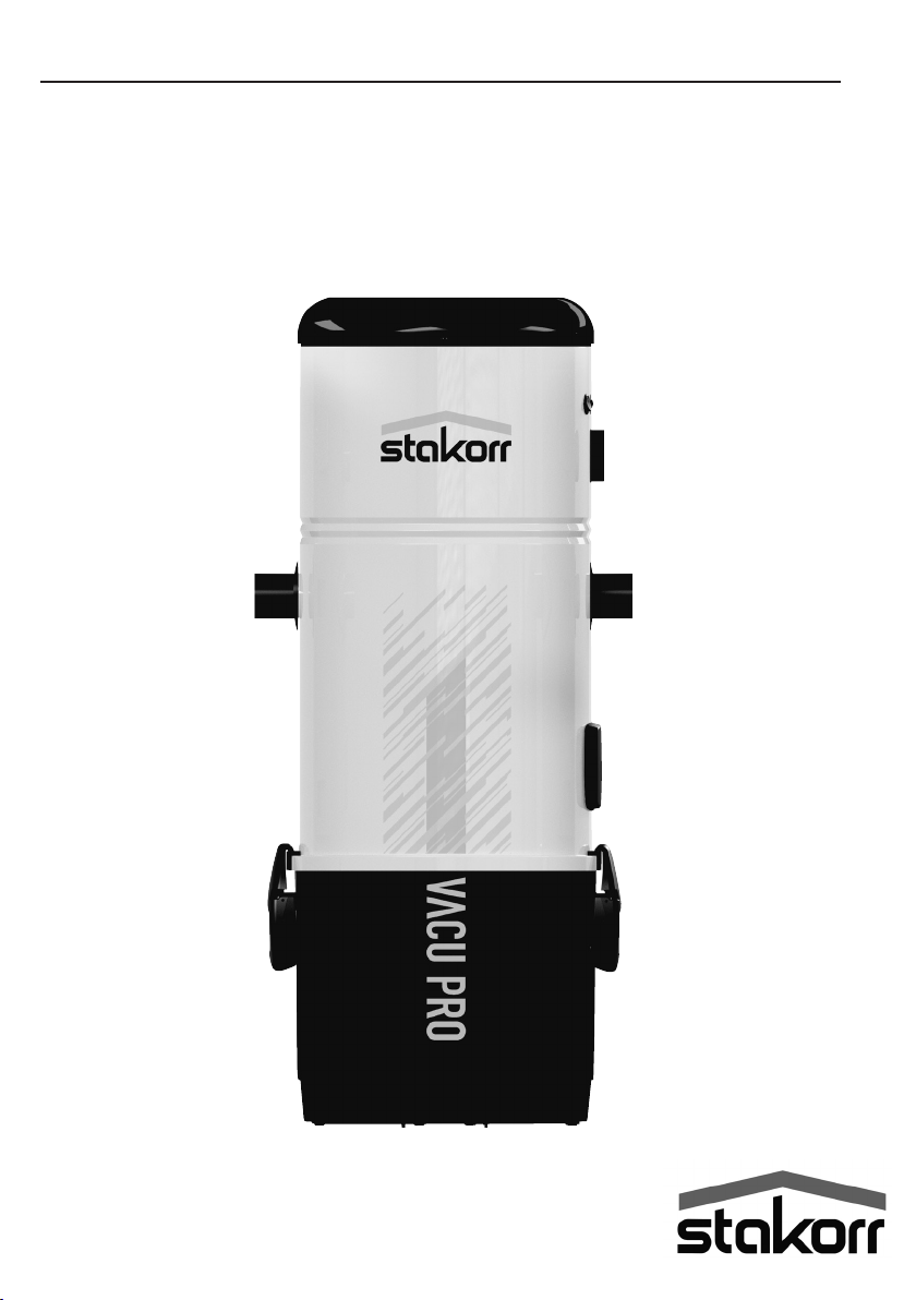
stakorr Vacu PRO Quick start guide
ENG: Installation, Use and Maintenance Instructions
Central Vacuum Unit Vacu PRO


27/04/2022 Rev:1.0.0
3
• Type: Domestic Central Vacuum Unit
• Model: Vacu Pro
• Revision 1.0.0
VACU PRO
INSTRUCTION MANUAL
1 TECHNICAL DATA 4
2 AUTHORIZED USE OF THE VACUUM CLEANER 6
3 UNAUTHORIZED USE OF THE VACUUM CLEANER 6
4 SAFETY FEATURES 7
4.1 Warning 7
4.2 Protection Degree 8
4.3 Electrical insulation degree 8
4.4 Declaration of absence of dangerous substances 8
4.5 Fixed closure guards safety 8
4.6 Movable closure guards safety 8
4.7Identicationplate 9
5 PACKAGE CONTENTS 10
6 INSTALLATION 11
6.1Preliminaryoperations 11
6.2 Place of installation 11
6.3 Fixing the vacuum cleaner to the wall 12
6.4Connectiontothepipingnetwork 13
6.5 Electrical connection 15
6.6Usingtheservicesocket 16
7 MAINTENANCE 16
7.1 Programmed routine maintenance 16
7.2 Cleaning the suction container (cylinder) 16
7.3Emptyingthedustbin 17
7.4Disposaloftheltercartridge 18
8 REPAIRS AND SPARE PARTS 18
8.1 Intervention criteria 18
8.2Recommendedspareparts 18
9 THERMAL SWITCH 18
10 TROUBLE SHOOTING 19
INDEX
Instruction manual
4
27/04/2022 Rev:1.0.0
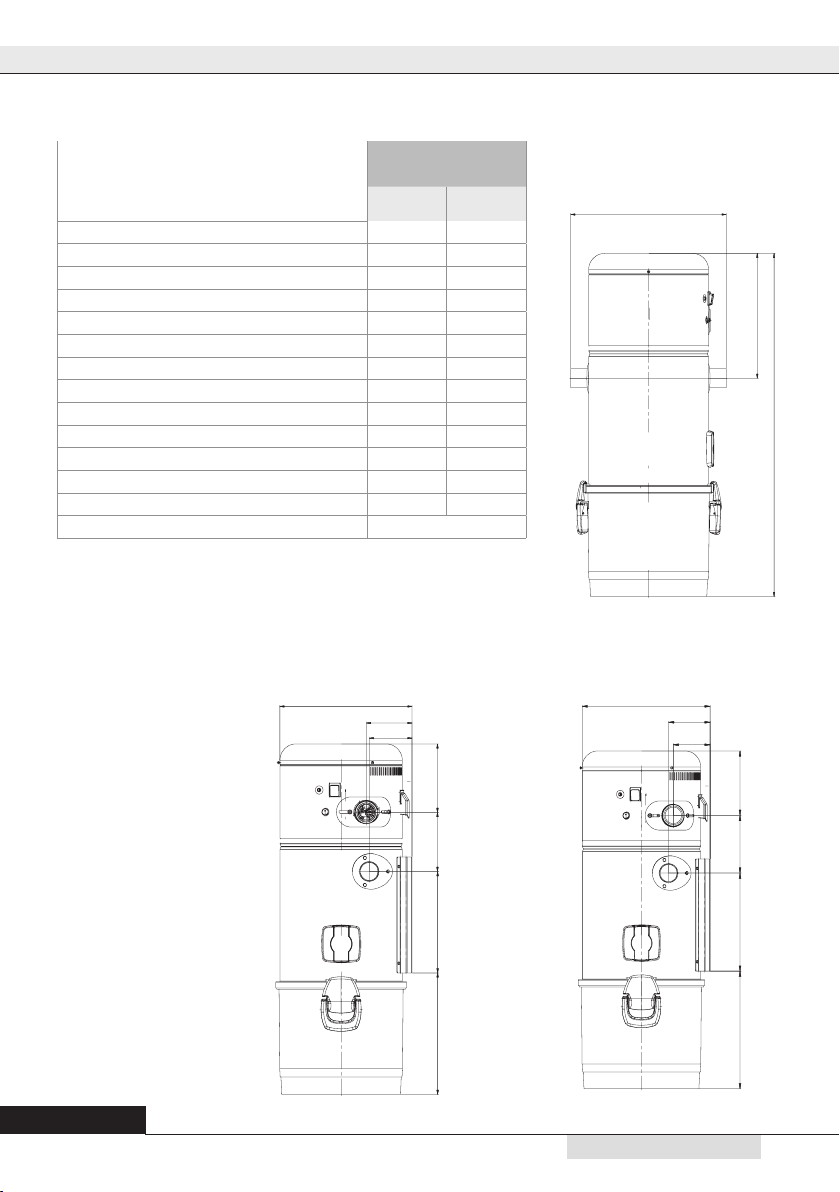
1- TECHNICAL DATA
N. B: Levels of nominal noise. The levels can vary according to the environment
where the central unit has been installed and the kind of installation
Art. 2330/2340
Art. 2330 Art. 2340
Articolo
VACU PRO
2330 2340
Suction coupling Ø mm 50 50
Air exhaust Ø mm 50 50
IP Protection Degree IP 20 20
Power supply V ac 220-230 220-230
Frequency Hz 50/60 50/60
Motor power kW 1,8 1,9
Absorption A 7,9 8,2
Socket power supply
V dc 12 12
Maximum air ow m3/h 240 257
Dust bin capacity l 25 25
Air venting YES YES
Air exhaust silencer YES YES
Weight kg 10,5 10,5
Sound level dB(A) < 70
346
120
112
177153262314
346
112
99
173154262315
415
330
907

5
2
27/04/2022 Rev:1.0.0
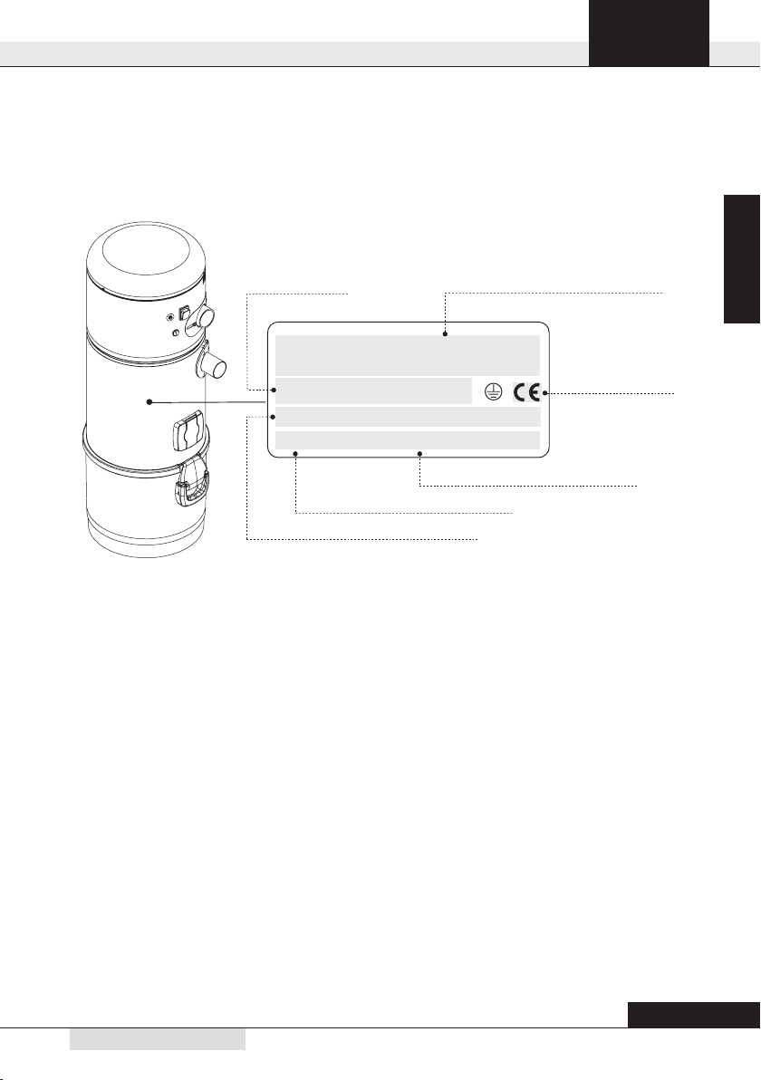
English
Main switch
Thermal switch
Air exhaust
ON/OFF switch
service inlet
Service vacum inlet
Closing handle and
hook
Dust bin
Dust inlet
1
2
3
4
6
7
8
5

Instruction manual
6
27/04/2022 Rev:1.0.0
2 - AUTHORIZED USE OF THE VACUUM CLEANER
The vacuum cleaner model Vacu Pro has been designed exclusively to vacuum clean house dust, very
small-size solids and dry materials. The use of the central vacuum cleaner is authorized for household
andciviluses,connectedtoaPVCwall-tracedpipingnetworkandtoastandardhomeelectricalwiring.
The vacuum cleaner can be installed in domestic dwellings with the following characteristics:
•Pipingnetworkfeaturing50-mmdiameterpipe
•220/240Vacpowersupply
• Air exhaust conveyed to the outside
•Suitableforasingle-operatoruse
•
Suitableforinstallationindomesticspacessuchasstorerooms,boilerrooms,garagesandbalconie
s.
3 - UNAUTHORIZED USE OF THE VACUUM CLEANER
It is extremely important NOT to use the system in the following circumstances which are consi-
dered to be inappropriate and dangerous:
•Neverusethemachineforunauthorizedpurposes.
• Never vacuum clean liquids.
• Do not vacuum clean fabrics, heavy materials, ashes or hot embers.
•Donotsuctioncement,ourorsimilarmaterials,includingtheconstructionsitedust(limeremains,
plasterpowderandsoon)whichmaycausethereductionofthevacuumedairwithaconsequentda-
mage of the motor.
The system has not been designed to be used in environments with risk of explosion, and the-
refore:
•itisforbiddentovacuumcleanmaterialswithhighexplosionrisk(gunpowder)ormaterialswhichare
individuallyinertbutthat,oncecollectedandmixedinthedustbin,couldprovokedangerouschemical
reactions.
•Itisabsolutelyforbiddentousethevacuumcleanerinexplosiveatmosphereoroutsidethestandard
temperature,pressureandhumiditylevels.
• Do not vacuum any material which may cause electrostatic charges in the piping system, if not
previously communicated to the constructor.
Any use of the appliance other than those specied above is forbidden.
Any change or modication made to the system in order to vacuum clean a particular type of
material must obtain the prior written approval of the manufacturer.
The use of the system for purposes other than those for which it was manufactured, represents
an irregular condition which can cause damage to the product and seriously compromise the
operator’s safety.

7
2
27/04/2022 Rev:1.0.0
English
4 - SAFETY FEATURES
WARNING: The manufacturer declines any form of responsibility or guarantee if the purchaser, or
anyoneinhisstead,makeseventheslightestmodicationoradjustmenttothepurchasedproduct.
Theunithasbeendesignedtosatisfyatbestthepresentneedsofthedomesticcentralvacuumclea-
nersmarket,bothintermsofqualityandoperatingcapacity.
AllmaterialsandcomponentsusedtomanufacturethisproductcomplywithCEsafetyregulations.
IncompliancewithsafetyregulationsdetailedintheMachineryDirective2006/42/CE(transposedinto
the Italian Legislation by Decree Law 17/10), in the Low Voltage Directive 2006/95/CE, and in the
ElectromagneticCompatibilityDirective2004/108/CE,theVacuProsystemcomplieswiththestandard
establishedforelectricalappliancesforhouseholdandsimilarpurposesEN60335-1(2008)andwiththe
RegulationCEN60335-2-2(2011),speciallyconceivedforvacuumcleanersforhouseholdandsimilar
purposeswithratedvoltagenotexceeding250V.
It is recommended to read carefully all the installation, use and maintenance instructions
detailed in this manual.
4.1 Warning
•Keepchildrenawayfromthevacuumcleanerwhilstinfunction.Childrenshouldnotplaywiththema-
chinenorwiththesuctionsockets.
•Thisequipmentshouldnotbeusedbypeople(includingchildren)withreducedpsychic,sensoryor
mentalcapacitiesorbypeoplewithnoexperiencenorknowledgeofthesystem,unlesstheyareunder
theguidanceorinstructedtousethemachinebypeopleresponsiblefortheirsafety.
•Childrenmustalwaysbesupervisedtoensuretheydonotplaywiththemachine.
•Switchoffthepowersupplyimmediatelyif:
- The electric cable is damaged or worn
-Thevacuumcleanerhasbeenexposedtorainorexcessivehumidity
-Thevacuumcleanerhasbeenknockedortheoutercoverhasbeendamagedinanyway
-Youthinkthesystemrequiresmaintenanceorrepair
•
Wearprotectiveglovesandmasktocarryoutmaintenance,toemptythedustbinorreplaceandcleanthelter.
•Onlyuseoriginalsparepartsandaccessories.
•Donotusethesystemwithoutaltercartridge.
•Donotblocktheexhaustairpipesorthemotorcoolingintakes.
•Nopartofthebodyshouldcomeintocontactwiththesuctionaccessories.
•Useonlyonesuctionsocketatatime.
•Donotleavethesystemswitchedonwhennotusingitanddisconnectitfrompowersupplywhenthe
systemisnotgoingtobeusedforalongperiodoftime.
Finally, remind that pictograms or danger and warning signals can be found on those parts of the
equipmentwhere,ifnotstrictlyfollowed,potentialriskysituationsmayoccur.

Instruction manual
8
27/04/2022 Rev:1.0.0
4.2 Protection Degree
IP44:Theappliancefeaturesaprotectionagainstsolidobjectshavingasizeexceeding
1mmandprotectionagainstsplashesofwater(splashesofwaterfromanydirectionon
thecovermustnotproducedangerouseffects).
IP20:Apparatusprotectedagainstsolidpartslargerthan12mmbutnotprotectedagainst
theinltrationofwater.
4.3 Electrical insulation degree
CLASSI:Theappliancefeaturesbasicelectricalinsulation.
Must be connected to the ground circuit through the main electric circuit.
CLASSII:Theappliancefeaturesdoubleelectricalinsulation.Theydoesn’tneedaconnetion
to the ground circuit through the main electric circuit.
4.4 Declaration of absence of dangerous substances
Themanufacturer declaresthat itsproducts andappliances havebeenmanufacturedwithmaterials
whichcomplywiththerestrictionsestablishedbythehealthandenvironmentprotectionregulationsin
forceanddonotcontainSVHC-classiedsubstances(SubstanceofVeryHighConcern)incompliance
withCEregulation1907/2006(REACH: i.e.Registration,Evaluation,AuthorizationandRestrictionof
ChemicalSubstances).Althoughthesesubstanceshavenotbeenusedduringtheprocessingcyclesof
rawmaterialsandduringthemanufacturingcyclesofourproducts,theirpresenceinp.p.m.(partsper
million)cannotbecompletelyexcludedduetomicro-pollutionofrawmaterials.
4.5 Fixed closure guards safety
ThevacuumcleanerisdeliveredtotheCustomerwithitsmainbodycompletelyassembled.Movingparts
(suctionmotor turbineblades)areprotectedbyaprotectiongriddirectlyassembled ontheinlet ofthe
suctionmotorcompartment.Thisprotectiongridcannotbeaccessedbytheoperator.Theoperatoralso
doesnothaveaccesstotheelectrically-operatedpartsoftheappliancewhichareprotectedbyacover
whichcanonlyberemovedbyunscrewingtheTorsenscrewsusedtoxthesoundproongdomeofthe
housing where the suction motors are assembled.
Everyinterventiononthecontrolboardandonthemotorsmustbecarriedoutbyqualiedpersonnelonly
afterdisconnectingtheelectricalpowersupplyandbyremovingtheelectricplugfromtheelectricsocke
4.6 Movable closure guards safety
Therearenomovableclosureguardsassembledontheappliance.Everyguardassembledisconside-
redaxedguardandisfastenedwithspecialscrews.Themanufacturerremindsyouthatitisabsolutely
forbiddentoreplacethescrewsusedforthedesignandmanufactureoftheapplianceswithscrewsthat
feature different characteristics.
Themanufacturerwillimmediatelysuspendtheproductguaranteeincaseofmachinetamperingcarried
out by the Customer.
IP20
9
2
27/04/2022 Rev:1.0.0
English
4.7 Identication plate
TheCEidenticationplateisassembledonthesideoftheconnectiontothepipingnetwork.Thisshould
not be removed or damaged.
....................................
.........................................................................
IP20
Model:
P/N: S/N:
ManufacturerIdentication
Technical data of the electric motor
Serial Number
TypeofCentralvacuumcleaner
Article
CE conformity
marking

Instruction manual
10
27/04/2022 Rev:1.0.0
5- PACKAGE CONTENTS
Thesalespackageofthecentralvacuum,inadditiontotheequipmentandthismanual,alsoincludes
theaccessorykit,consistingofthefollowingparts:
1) N°1wallmountingbracketforxingthecentralvacuumunittothewall
2) N°1rubbersleevesforconnectiontothevacuumpipenetwork
3) N°3metalclampsforxingthesleeves
4) N°1 installation, use and maintenance manual
5) N°1plasticairexhaustsilencerforairdischarge
1 2 3
45
MANUALE TECNICO
S
.l.

11
2
27/04/2022 Rev:1.0.0
English
6 - INSTALLATION
- WARNING -
THESE PROCEDURES MUST BE CARRIED OUT
BY QUALIFIED PERSONNEL
6.1 Preliminary operations
Thesuctionsystemisshippedtothecustomercompletelyassembledandpacked.
Beforeswitchingthemachineon,thefollowingchecksareadvisable:
•Checkthatthepackagingisintact.
•Checkthattheappliancehasnotbeendamagedinanywayandinparticularcheckthatallthepro-
trudingpartsareintact.
•Verifythecorrecttighteningoftheltercartridge.
•Usingtheequipmentlistandthekitandaccessorieslist,checkthattheequipmentandthekithave
beenexactlyandcompletelydelivered.
•CheckthattheGuaranteeCerticatehasbeenprovided.
Ifanydamageorirregularityisfoundorifanyaccessoryismissing,donotinstalltheapplianceand
contact your Retailer.
6.2 Place of installation
Theuseofthevacuumcleanerrequiresasuctionpipingnetworkinstalledbyqualiedpersonnelwho
has already selected the most suitable location.
Belowyouwillndthemainindicationstobefollowedforacorrectinstallation:
• Iftheappliancewillbeconnectedtoapipenetworkonmorethanoneoor,wesuggestyoutoinstall
itinthelowestpartofthebuilding.
• Installthesysteminservicerooms(e.g.garageorstorageroom)awayfrombadweather,dampness
andexcessivetemperaturevariations.
• Chooseaplacefarfromheatsourcessuchasstovesandradiators.
• Makesurethatthereissufcientspacearoundthesystemandthatthesurroundingareaiswelllitto
facilitatetheinterventionsformaintenanceandrepairs.
Whenthevacuumcleaner,forspecicinstallationneeds,isinstalledonthehighestoorsofthebu-
ildingwithregardtothelevelwherethepipenetworkishoused(attic,garretetc.),wesuggestyouto
installavacuumcleanerfeaturingapowercategoryhigherthantheoneneededtocleanthedesired
surface.
Foranyfurtherinformation,donothesitatetocontacttheManufacturer’sTechnicalService.
Instruction manual
12
27/04/2022 Rev:1.0.0
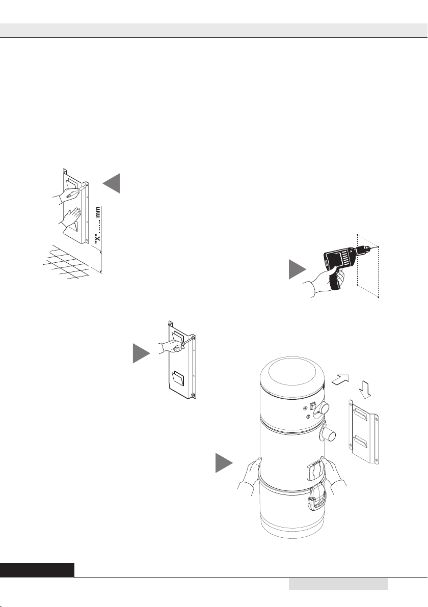
Tracethedrillingpositionusingthe
templateprovided(drillingtemplate);if
thishasalreadybeendone,proceedto
thenextstep.
6.3 Fixing the vacuum cleaner to the wall
Thevacuumcleanermustbesecurelyandpermanentlyxedtoasolidwallusingthebracketprovided
andthesuitablewallanchorsorplugstakingintoaccountthatthetotalweighttobesupportedcanbe
seven/eight times the weight of the system itself.
Thesystemshouldbepositionedhighenoughoffthegroundtoallowthedustcollectionbintobe
emptiedandtheltertobereplacedinasimpleway.
Positionthesystemsoastokeepaminimumdistanceof60cmaroundtheapplianceforextraordinary
maintenance.
Todothisfollowtheinstructionsdetailedbelow:
2
1
Drill the holes
Tighten the screws in
thewallplugsandcheck
thatthebracketiswell
anchored to the wall.
3
4
Hook the vacuum cleaner to the
anchoringbracketbyliftingit,leaning
it against the wall and allowing it to
slide down until it ts into the xing
plate.

13
2
27/04/2022 Rev:1.0.0
English
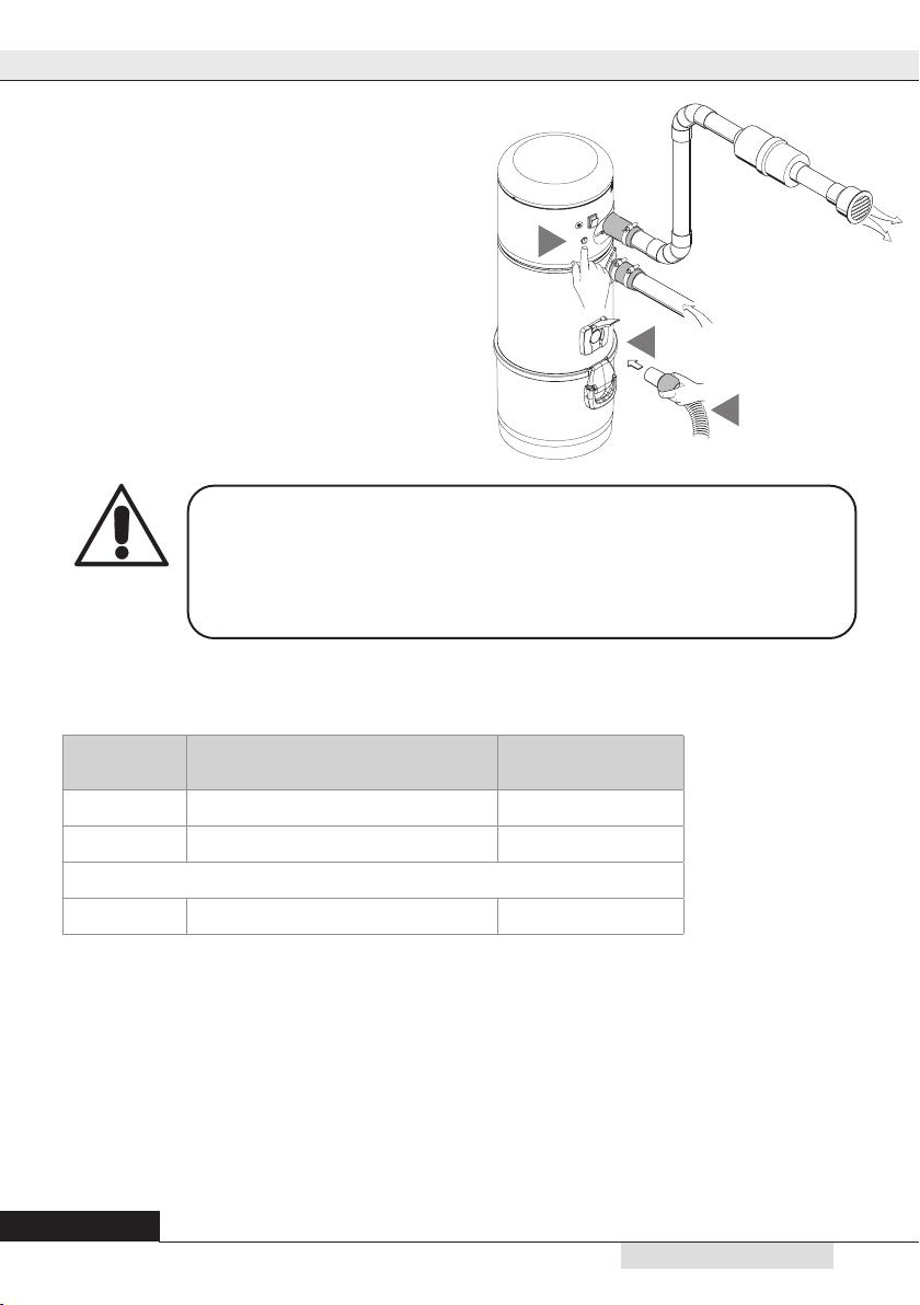
6.4 Connection to the piping network
1.Applytheclosingcap(A)ontheendoftheintakeconnectionnotusedforconnectingthepi-
pingnetwork(B),asopeningitwoulddecreasethecentralvacuumunit’svacuumpower.
A
D
E
B
C
2. Usingthesleeve,connectthedustinletcouplingofthecyclonicvacuumcleaner,identiedwith(C)
inthepicture,tothesuctionpipefromthepipingnetwork.
3. Byusingthesleeve,connecttheairoutletofthecentralvacuumunit,markedwith(D),totheair
outlet of the house.
4. Gluethesilencer(E)ontheexhaustpipeneartheexhaustairgrid.
N.B.:donotgluethepipeendofthenetworkpipetothedustinletcouplingortotheairexhaustcou-
pling:alwaysusethesleevesprovided.

Instruction manual
14
27/04/2022 Rev:1.0.0
B
C
Should it be necessary to convey the air discharge to the outside, please follow the following
instructions:
Maximum length of the discharge pipe:
N.B. Diameter of the outlet pipe for a length up to 10 m: 50 mm
Exhaust pipe diameter for lengths over 10 m: 63 mm

15
2
27/04/2022 Rev:1.0.0
English
WARNING: the electrical connection must be carried out
ONLY by qualied personnel.
MicroLine/Suctionsocket
12V
PowersupplyAC230V
6.5 Electrical connection
Beforeconnectingthesystemtotheelectricalpowersupplycheckthatthesupplyvoltagecorresponds
totheonerequiredbythevacuumcleaner(seetheidenticationplate).
Themanufacturerdeclinesanyresponsibilityfordamagestopeopleand/orobjectsduetotheconnec-
tiontoanon-complyingelectricwiring.
Followtheinstructions(seepicture)detailedbelowtocarryouttheoperation:
• Connecttheinputsignalcable(MICROLINE)tothesuctionsockets.
• Inserttheplugofthepowersupplycablefromthecentralsystemintheelectricsocket.
• Checkthattheelectricalwiringofthehousehasbeensetupincompliancewiththeelectricalregula-
tions in force.
• Donotpowerthesystemwithsupplyvoltagefromprovisionalortemporaryswitchboards(forexample
constructionsitesswitchboards)toavoidpossibledamagetotheelectronicparts.
Instruction manual
16
27/04/2022 Rev:1.0.0
7 - MAINTENANCE
7.1 Programmed routine maintenance
Maintenance should be carried out according to the effective running time of the system to ensure
efcientperformanceandtoavoidseriousmechanicaldamages.
7.2 Cleaning the suction container (cylinder)
Periodicallycleantheoutsidecasingofthevacuumcleanerwithasoftdampclothwithwaterandneutralsoap.
Important: only use water or neutral soap and water to clean the vacuum cleaner. The use of other
solvents or alcohol can entail damages. Ensure the system’ s surface is completely dry before
switching it back on.
Alwaysuseasuitablemasktoprotectagainstairbornedustandwearlatexglovestoprotectyourhand
skin.
BEFORE CARRYING OUT ANY MAINTENANCE
OPERATION, IT IS MANDATORY TO UNPLUG THE POWER
SUPPLY CABLE FROM THE POWER SUPPLY INLET.
PROTECTIVE MASK AND GLOVES MUST
ABSOLUTELY BE WORN
Working time
(h)
Maintenance Executor
6 Filter cleaning User
6 Emptying the dust container User
every 4 years Substitution of lter cartridge User
6.6 Using the service socket
1. Insert the hose (A) directly in the service outlet (B
- see the drawing), after lifting the cover.
2.Press the switch (C) on the frontal panel of the
machinetostartandstopsuction.
A
B
C
17
2
27/04/2022 Rev:1.0.0
English
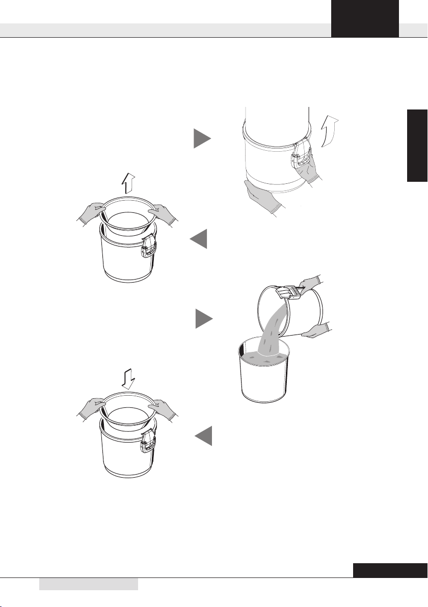
7.3 Emptying the dust bin
SwitchthesuctionsystemoffbypressingtheON/OFFswitch.
Remove the conveyor cone
2
Remove the dust bin 1
Emptythedustbin 3
Puttheconveyorconebackinposition
4
Reassemblethedustbininsideitshousingunderthesuctionsystemandlocktheclosinghandles.
SwitchthesuctionsystemonbypressingtheON/OFFswitch.
Remember to be careful when emptying the bin: if there is a big quantity of dust, make sure you
do not throw away the conveyor cone. Always check that the conveyor cone is still in place and
correctly assembled in its housing inside the bin.
Instruction manual
18
27/04/2022 Rev:1.0.0
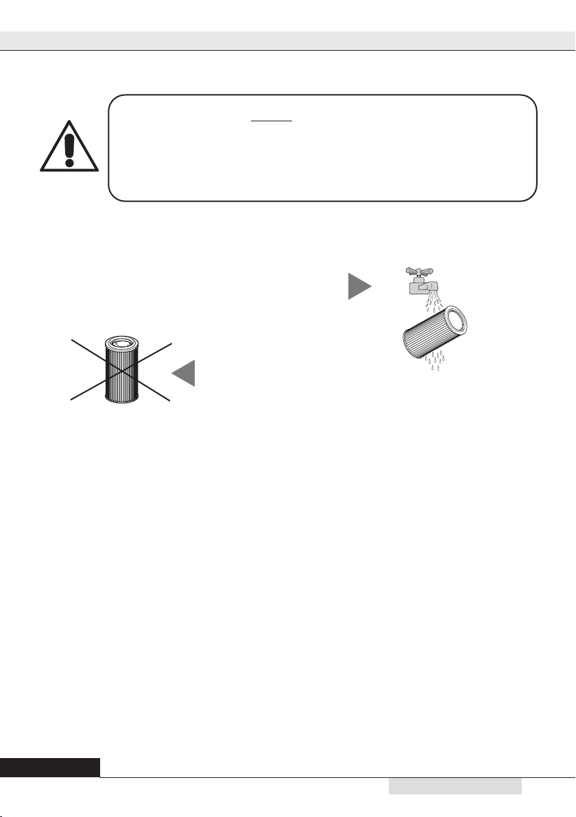
7.4 Disposal of the lter cartridge
Theltercartridgecanbereusedafterwashingitunderrunningwater.
ATTENTION: before replacing the lter cartridge back in the system after washing, ensure it has
completely dried. DO NOT reassemble the lter cartridge if the surface is still wet or damp
Check that the lter surface is not
cut. If this is the case, the cartridge
should not be used again and
shouldbedenitelyreplaced.
2
Before washing the cartridge it is always recommended to
vacuum clean the dirty surface with an auxiliary suction cleaner
orwiththeutility/serviceinlet,rememberingtoinsertaspare
cartridge in the system before use.
1
ATTENTION
YOU SHALL ALWAYS CHECK THE RIGHT POSITIONING AND TIGHTENING
OF THE FILTER CARTRIDGE. A WRONG POSITIONING MAY CAUSE
A SERIOUS DAMAGE OF THE PRODUCT.
DO NOT USE THE VACUUM CLEANER WITHOUT THE FILTER CARTRIDGE.
ENSURE YOU HAVE REPLACED A SPARE FILTER CARTRIDGE BEFORE
CARRYING OUT THIS OPERATION.
8 - REPAIRS AND SPARE PARTS
8.1 Intervention criteria
Anyinterventiononthevacuumcleanerforrepairsand/ormaintenancewhicharenotexpresslyauthorized
in this manual is absolutely forbidden.
AnyrepairforbreakageormalfunctioningmustbecarriedoutbyqualiedTechnicalAssistancepersonnel.
Anyinterventionofnon-authorizedpersonnelwillresultintheinvalidationofanyguaranteeoftheproduct
andthemanufacturerwillnotbeheldresponsibleforanyeventualdamagetopersonsand/orobjectsdue
to such interventions.
8.2 Recommended spare parts
Itisadvisabletoorderintimethosesparepartswhichneedtobechangedmoreoften.
Inordertoguaranteetheoptimalandlongworkinglifeofthevacuumcleaneritisrecommendedtouse
onlyoriginalspareparts
9 THERMAL SWITCH
Thethermalswitchpreventsdamagestotheelectricandelectronicpartsfrompoweroverloadsandfrom
short-circuits. The switch button is located inside its lodging during the regular functioning of the machine,
whileincaseofactivatedprotectionitwillbeoutofitslodging.Thereactivationoftheswitchmustbedone
manuallybypushingthebuttonbackintoitslodging.Thisoperationwillbeeffectiveonlyifthecauseof
theblockinghasbeenxed.Iftheblockingoccursregularly,itisadvisabletoletaspecializedtechnician
verify the correct functioning of the machine.

19
2
27/04/2022 Rev:1.0.0
English
10 - TROUBLE SHOOTING
PROBLEM CAUSE SOLUTION
There is no suction from any of the
suctionsockets
Thepowercableisunplugged Connectthepowercable
The start button is on OFF
position Press the Start button
The micro line cable is not
connected
Connect the activation cable
(sensor)
Thethermalprotectionofthe
motor has intervened
Allowafewminutesstopfor
the motor to cool down
The thermal switch has
intervened
Press the restart button on the
thermail switch
Thereisnoairsuctionfromjustone
suctionsocket
Theelectriccontactsareinterruptedorthe
micro-switchofthesuctionsocketisout
of order
Call the Technical Service
Theairsuctionisweak
Morethanonesuctionsocketisbeingusedat
thesametimeand/ortheservicesuctionsocket
isworking
Use only one suction inlet at
a time
Theexiblehoseorthe
cleaning accessories are
broken
Checktheexiblehoseandtheaccessories
are not damaged (change them if
necessary)
Theltercartridgeisdirty Cleantheltercartridge
Thesealinggasketofthedust
bin is damaged
Checksealinggasket
integrity
There is a clogging in the suction
pipesofthepipe
network
Call the Technical Service
The air exhaust outlet is
blocked Call the Technical Service
Thevacuumcleanerstillworkseven
when the suction inlets are closed
Fault of the electronic board Call the Technical Service
Thesuctionworksintermittentlywiththe
hose inserted in the inlet.
Thethermalprotectionofthe
motor has intervened
Checkforapossibleclogging
inthepipingnetwork
Checkforapossibleclogging
intheairdischargepipe
Remove the hose from the
suctioninletandwaitacouple
of minutes to let the motor
cool down
Call the Technical Service

F0920620
36031 Dueville (VI) ITALIA - Via Prati, 11
Tel. + 39 0444 1803418 - info@stakorr.it
Table of contents


