Stanley PR41 User manual

PR41
HYDRAULIC
PRUNER
WARNING
Stanley Hydraulic Tools
3810 SE Naef Road
Milwaukie OR 97267-5698
503-659-5660
FAX 503-652-1780
www.stanley-hydraulic-tools.com
© Stanley Hydraulic Tools 2005
SVCE/MAINT USA / CE
Printed in U.S.A.
32471 9/2005 ver 2
SAFETY, OPERATION AND MAINTENANCE
SERVICE MANUAL


TABLE OF CONTENTS
SAFETY SYMBOLS ...............................................................................................................................................................................................................4
SAFETY PRECAUTIONS.......................................................................................................................................................................................................5
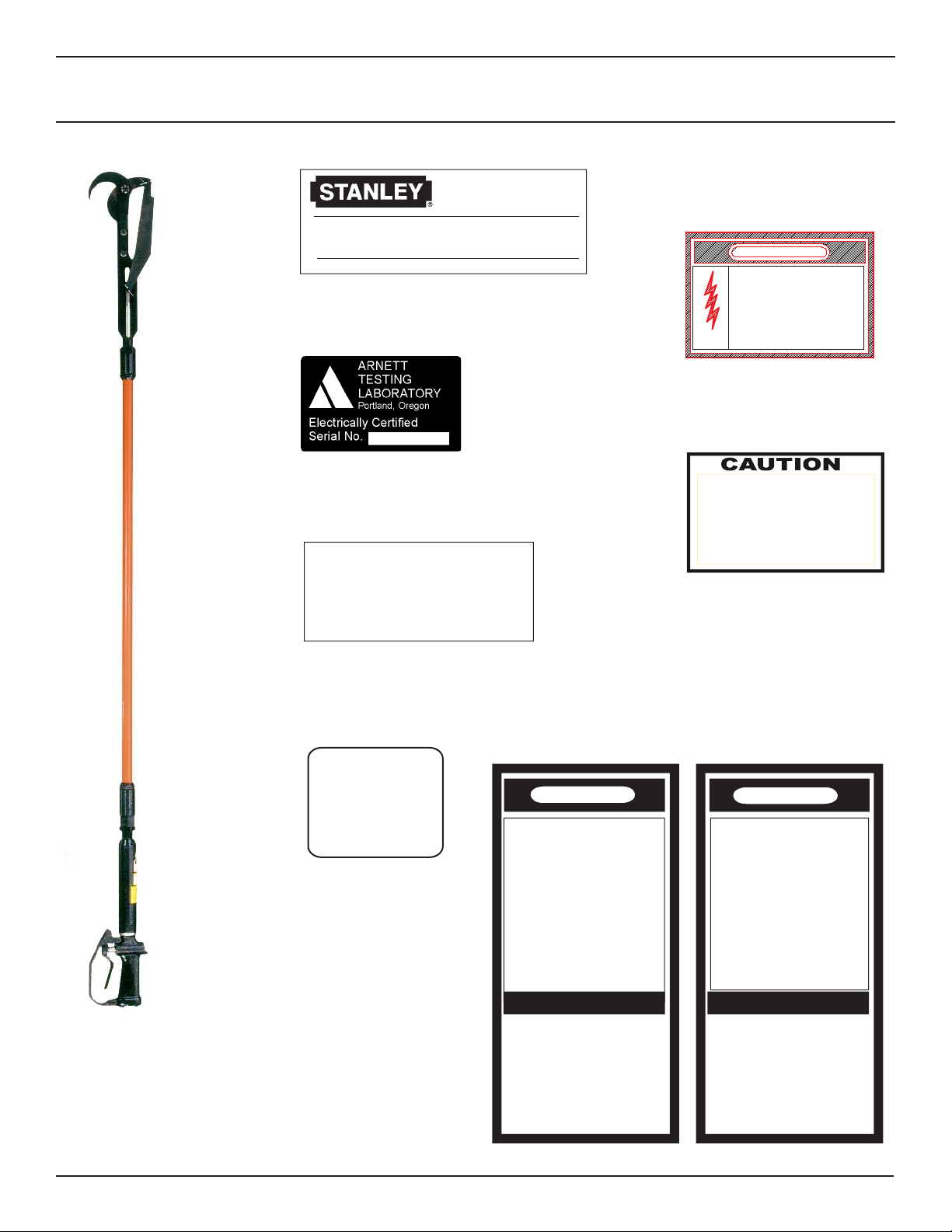
TOOL STICKERS & TAGS .....................................................................................................................................................................................................7
HYDRAULIC HOSE REQUIREMENTS..................................................................................................................................................................................8
HTMA REQUIREMENTS........................................................................................................................................................................................................9
OPERATION.........................................................................................................................................................................................................................10
PREPARATION FOR INITIAL USE ..................................................................................................................................................................................10
CHECK HYDRAULIC POWER SOURCE ........................................................................................................................................................................10
CHECK TOOL ..................................................................................................................................................................................................................10
CHECK TRIGGER MECHANISM.....................................................................................................................................................................................10
CONNECT HOSES ..........................................................................................................................................................................................................10
OPERATING PROCEDURES ..........................................................................................................................................................................................10
EQUIPMENT PROTECTION & CARE .................................................................................................................................................................................12
TROUBLESHOOTING .........................................................................................................................................................................................................13
SPECIFICATIONS................................................................................................................................................................................................................14
ACCESSORIES ...................................................................................................................................................................................................................14
SERVICE..............................................................................................................................................................................................................................15
PRIOR TO DISASSEMBLY ..............................................................................................................................................................................................15
PRUNER DISASSEMBLY ................................................................................................................................................................................................15
KNIFE BLADE, HOOK, LINK BAR & SLIDE HEAD DISASSEMBLY ..............................................................................................................................15
EXTERNAL TUBE ASSEMBLY ........................................................................................................................................................................................15
INTERNAL TUBE ASSEMBLY .........................................................................................................................................................................................15
TUBE COUPLING ............................................................................................................................................................................................................15
PISTON & PISTON ROD .................................................................................................................................................................................................15
CYLINDER & CYLINDER OIL TUBE ...............................................................................................................................................................................15
VALVE HANDLE ASSEMBLY...........................................................................................................................................................................................15
PARTS INSPECTION.......................................................................................................................................................................................................16
KNIFE BLADE, HOOK, LINK BAR & SLIDE HEAD ASSEMBLY .....................................................................................................................................16
INTERNAL TUBE .............................................................................................................................................................................................................16
EXTERNAL TUBE ............................................................................................................................................................................................................16
PISTON ROD & PISTON .................................................................................................................................................................................................16
VALVE SPOOL & VALVE HANDLE ..................................................................................................................................................................................16
HYDRAULIC SUPPLY......................................................................................................................................................................................................16
PRUNER ASSEMBLY ......................................................................................................................................................................................................16
VALVE HANDLE ASSEMBLY...........................................................................................................................................................................................16
CYLINDER & CYLINDER OIL TUBE ...............................................................................................................................................................................16
PISTON & PISTON ROD .................................................................................................................................................................................................16
TUBE COUPLING ............................................................................................................................................................................................................17
INTERNAL TUBE ASSEMBLY .........................................................................................................................................................................................17
EXTERNAL TUBE ASSEMBLY ........................................................................................................................................................................................17
KNIFE BLADE, HOOK, LINK BAR & SLIDE HEAD DISASSEMBLY ..............................................................................................................................17
TESTING FOR OPERATION & PERFORMANCE ...........................................................................................................................................................18
PARTS ILLUSTRATION .......................................................................................................................................................................................................19
PARTS LIST .........................................................................................................................................................................................................................20
WARRANTY .........................................................................................................................................................................................................................21
3
For the nearest authorized and certified dealer, call Stanley Hydraulic Tools at the number listed on the back of
this manual and ask for a Customer Service Representative.
SERVICING THE STANLEY HYDRAULIC Pruner. This manual contains safety, operation, and routine maintenance
instructions. Stanley Hydraulic Tools recommends that servicing of hydraulic tools, other than routine mainte-
nance, be performed by an authorized and certified dealer. Please read the following warning.
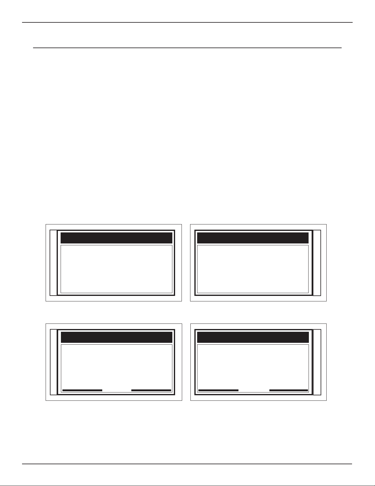
SERIOUS INJURY OR DEATH COULD RESULT FROM THE IM-
PROPER REPAIR OR SERVICE OF THIS TOOL.
REPAIRS AND / OR SERVICE TO THIS TOOL MUST ONLY BE
DONE BY AN AUTHORIZED AND CERTIFIED DEALER.
WARNING

4
Safety symbols and signal words, as shown below, are used to emphasize all operator, maintenance and repair
actions which, if not strictly followed, could result in a life-threatening situation, bodily injury or damage to equip-
ment.
This safety alert and signal word indicate an imminently hazardous situa-
tion which, if not avoided, will result in death or serious injury.
Always observe safety symbols. They are included for your safety and for the protection of the tool.
LOCAL SAFETY REGULATIONS
Enter any local safety regulations here. Keep these instructions in an area accessible to the operator and mainte-
nance personnel.
CAUTION
WARNING
DANGER
NOTICE
This is the safety alert symbol. It is used to alert you to potential personal
injury hazards. Obey all safety messages that follow this symbol to avoid
possible injury or death.
This safety alert and signal word indicate a potentially hazardous situation
which, if not avoided, could result in death or serious injury.
This safety alert and signal word indicate a potentially hazardous situation
which, if not avoided, may result in minor or moderate injury.
This signal word indicates a potentially hazardous situation which, if not
avoided, may result in property damage.
This signal word indicates a situation which, if not avoided, will result in
damage to the equipment.
This signal word indicates a situation which, if not avoided, may result in
damage to the equipment.
IMPORTANT
SAFETY SYMBOLS

5
Tool operators and maintenance personnel must always comply with the safety
precautions given in this manual and on the stickers and tags attached to the tool
and hose.
These safety precautions are given for your safety. Review them carefully before
operating the tool and before performing general maintenance or repairs.
Supervising personnel should develop additional precautions relating to the specific
work area and local safety regulations. If so, place the added precautions in the
space provided in this manual.
The models PR41 Hydraulic Pruner will provide safe and dependable service if
operated in accordance with the instructions given in this manual. Read and un-
derstand this manual and any stickers and tags attached to the pruner and hoses
before operation. Failure to do so could result in personal injury or equipment dam-
age.
• Operator must start in a work area without bystanders. The operator must be familiar with all prohibited work areas
such as excessive slopes and dangerous terrain conditions.
• Establish a training program for all operators to ensure safe operation.
• Do not operate the tool unless thoroughly trained or under the supervision of an instructor.
• Always wear safety equipment such as goggles, ear and head protection, and safety shoes at all times when operating
the tool.
• Do not inspect or clean the tool while the hydraulic power source is connected. Accidental engagement of the tool can
cause serious injury.
• Always connect hoses to the tool hose couplers before energizing the hydraulic power source. Be sure all hose con-
nections are tight.
• Do not operate the tool at oil temperatures above 140°F/60°C. Operation at higher temperatures can cause higher
than normal temperatures at the tool which can result in operator discomfort.
• Do not operate a damaged, improperly adjusted, or incompletely assembled tool.
• Do not inspect, clean or replace the pruner blade while the hydraulic power source is connected.
• Never wear loose clothing that can get entangled in the working parts of the tool.
• Keep all parts of your body away from the pruner blade.
• Do not overreach. Maintain proper footing and balance at all times.
• Keep the pruner blade off all surfaces when starting the tool.
• If used near energized electric lines, maintain working distances according to OSHA guidelines for working near ener-
gized lines (ref. Section 1926.950). Failure to comply with this warning could result in serious personal injury.
• To avoid personal injury or equipment damage, all tool repair, maintenance and service must only be performed by
authorized and properly trained personnel.
• Never cock, jam or wedge the blade during operation.
• Eye injury, and cutting or severing of body parts is possible if proper procedures are not followed.
SAFETY PRECAUTIONS

6
SAFETY PRECAUTIONS
• Ensure that the blade is correctly mounted before use.
• If the tool is dropped with a blade installed, the blade and associated parts should be examined
throughly before use.
• Only use blades manufactured by Stanley Hydraulic Tools. Stanley assumes no responsibility for failure in equipment,
accidental damage, or accidental injury as a result of the use of blades not manufactured by Stanley Hydraulic Tools.
• Always ensure the blade is sharp. Do not try to use the tool with a dull blade.

7
The safety tag (p/n
15875) at right is attached
to the tool when shipped
from the factory. Read
and understand the safety
instructions listed on this
tag before removal. We
suggest you retain this tag
and attach it to the tool
when not in use.
TOOL STICKERS & TAGS
(shown smaller then actual size)
SAFETY TAG P/N 15875
IMPORTANT
READ OPERATION MANUAL AND
SAFETY INSTRUCTIONS FOR THIS
TOOL BEFORE USING IT.
USE ONLY PARTS AND REPAIR
PROCEDURES APPROVED BY
STANLEY AND DESCRIBED IN THE
OPERATION MANUAL.
TAG TO BE REMOVED ONLY BY
TOOL OPERATOR.
1. FAILURE TO USE HYDRAULIC HOSE LABELED
AND CERTIFIED AS NON-CONDUCTIVE WHEN
USING HYDRAULIC TOOLS ON OR NEAR
ELECTRICAL LINES MAY RESULT IN DEATH
OR SERIOUS INJURY.
BEFORE USING HOSE LABELED AND CERTI-
FIED AS NON-CONDUCTIVE ON OR NEAR
ELECTRIC LINES BE SURE THE HOSE IS
MAINTAINED AS NON-CONDUCTIVE. THE
HOSE SHOULD BE REGULARLY TESTED FOR
ELECTRIC CURRENT LEAKAGE IN ACCOR-
DANCE WITH YOUR SAFETY DEPARTMENT
INSTRUCTIONS.
2. A HYDRAULIC LEAK OR BURST MAY CAUSE
OIL INJECTION I N T O T H E
BODY OR CAUSE OTHER SEVERE PERSONAL
INJURY.
A DO NOT EXCEED SPECIFIED FLOW AND
PRESSURE FOR
IMPORTANT
READ OPERATION MANUAL AND
SAFETY INSTRUCTIONS FOR THIS
TOOL BEFORE USING IT.
USE ONLY PARTS AND REPAIR
PROCEDURES APPROVED BY
STANLEY AND DESCRIBED IN THE
OPERATION MANUAL.
TAG TO BE REMOVED ONLY BY
TOOL OPERATOR.
D DO NOT LIFT OR CARRY TOOL BY THE
HOSES. DO NOT ABUSE HOSE. DO NOT
USE KINKED, TORN OR DAMAGED HOSE.
3. MAKE SURE HYDRAULIC HOSES ARE PROP-
ERLY CONNECTED TO THE TOOL BEFORE
PRESSURING SYSTEM. SYSTEM PRESSURE
HOSE MUST ALWAYS BE CONNECTED TO TOOL
“IN” PORT. SYSTEM RETURN HOSE MUST
ALWAYS BE CONNECTED TO TOOL“OUT” PORT.
REVERSING CONNECTIONS MAY CAUSE RE-
VERSE TOOL OPERATION WHICH CAN RESULT
IN SEVERE PERSONAL INJURY.
4. DO NOT CONNECT OPEN-CENTER TOOLS TO
CLOSED-CENTER HYDRAULIC SYSTEMS. THIS
MAY RESULT IN LOSS OF OTHER HYDRAULIC
FUNCTIONS POWERED BY THE SAME SYSTEM
AND/OR SEVERE PERSONAL INJURY.
5. BYSTANDERS MAY BE INJURED IN YOUR WORK
AREA. KEEP BYSTANDERS CLEAR OF YOUR
WORK AREA.
DANGER DANGER
Failure to use hydraulic hose labeled and certified
as non-conductive when using hydraulic tools on
or near electric lines may result in death or
For proper and safe operation read owners manual
and mwke sure that you have been properly
trained in correct procedures required for work
serious injury.
serious injury.
on or around electric lines.
ELECTROCUTION
HAZARD
DANGER
12412
Electrical Warning Decal
3-9 GPM / 11-34 LPM
DO NOT EXCEED 2000 PSI / 140 BAR
DO NOT EXCEED SPECIFIED FLOW OR PRESSURE
USE CLOSED-CENTER TOOL ON CLOSED-CENTER
SYSTEM. USE OPEN-CENTER TOOL ON OPEN-CENTER
SYSTEM. CORRECTLY CONNECT HOSES TO TOOL “IN”
AND “OUT” PORTS. IMPROPER HANDLING, USE OR OTHER
MAINTENANCE OF TOOL COULD RESULT IN A LEAK, BURST
OR OTHER TOOL FAILURE. CONTACT AT A LEAK OR BURST
CAN CAUSE OIL INJECTION INTO THE BODY. FAILURE TO
OBSERVE THESE PRECAUTIONS CAN RESULT IN SERIOUS
PERSONAL INJURY.
03783
3-9 GPM Decal
Stanley Hydraulic Tools
3810 SE Naef Road
Milwaukie, Oregon 97267 U.S.A.
Model No.
PR41
Dielectric Certification Decal
28502
Name Tag
NOTICE
KEEP KNIFE SHARP.
A DULL KNIFE WILL GIVE A POOR
QUALITY CUT OR MAY CAUSE THE
KNIFE TO BREAK.
25910
Notice Decal
03693
Closed Center Decal
CLOSED
CENTER
FOR USE ON
CLOSED-CENTER
HYDRAULIC SYSTEM

8
HOSE TYPES
Hydraulic hose types authorized for use with Stanley Hydraulic Tools are as follows:
Certified non-conductive
Wire-braided (conductive)
Fabric-braided (not certified or labeled non-conductive)
Hose listed above is the only hose authorized for use near electrical conductors.
Hoses and listed above are conductive and must never be used near electrical conductors.
HOSE SAFETY TAGS
To help ensure your safety, the following DANGER tags are attached to all hose purchased from Stanley Hydrau-
lic Tools. DO NOT REMOVE THESE TAGS.
If the information on a tag is illegible because of wear or damage, replace the tag immediately. A new tag may be
obtained from your Stanley Distributor.
HOSE PRESSURE RATING
The rated working pressure of the hydraulic hose must be equal to or higher than the relief valve setting on the
hydraulic system.
THE TAG SHOWN BELOW IS ATTACHED TO “CERTIFIED NON-CONDUCTIVE” HOSE
THE TAG SHOWN BELOW IS ATTACHED TO “CONDUCTIVE” HOSE.
HYDRAULIC HOSE REQUIREMENTS
SIDE 1 SIDE 2
D A N G E R
DO NOT REMOVE THIS TAG
D A N G E R
1 FAILURE TO USE HYDRAULIC HOSE LABELED AND CERTIFIED AS NON-CONDUCTIVE
WHEN USING HYDRAULIC TOOLS ON OR NEAR ELECTRIC LINES MAYRESULT IN DEATH
OR SERIOUS INJURY.
FOR PROPER AND SAFE OPERATION MAKE SURE THAT YOU HAVE BEEN PROPERLY
TRAINED IN CORRECT PROCEDURES REQUIRED FOR WORK ON OR AROUND
ELECTRIC LINES.
2. BEFORE USING HYDRAULIC HOSE LABELED AND CERTIFIED AS NON-CONDUCTIVE ON
OR NEAR ELECTRIC LINES. WIPE THE ENTIRE LENGTH OF THE HOSE AND FITTING
WITH A CLEAN DRY ABSORBENT CLOTH TO REMOVE DIRT AND MOSISTURE AND TEST
HOSE FOR MAXIMUM ALLOWABLE CURRENT LEAKAGE IN ACCORDANCE WITH SAFETY
DEPARTMENT INSTRUCTIONS.
DO NOT REMOVE THIS TAG
3. DO NOT EXCEED HOSE WORKING PRESSURE OR ABUSE HOSE. IMPROPER USE OR
HANDLING OF HOSE COULD RESULT IN BURST OR OTHER HOSE FAILURE. KEEP
HOSE AS FAR AWAY AS POSSIBLE FROM BODY AND DO NOT PERMIT DIRECT CONTACT
DURING USE. CONTACT AT THE BURST CAN CAUSE BODILY INJECTION AND SEVERE
PERSONAL INJURY.
4. HANDLE AND ROUTE HOSE CAREFULLY TO AVOID KINKING, ABRASION, CUTTING, OR
CONTACT WITH HIGH TEMPERATURE SURFACES. DO NOT USE IF KINKED. DO NOT USE
HOSE TO PULL OR LIFT TOOLS, POWER UNITS, ETC.
5. CHECK ENTIRE HOSE FOR CUTS CRACKS LEAKS ABRASIONS, BULGES, OR DAMAGE TO
COUPLINGS IF ANY OF THESE CONDITIONS EXIST, REPLACE THE HOSE IMMEDIATELY.
NEVER USE TAPE OR ANY DEVICE TO ATTEMPT TO MEND THE HOSE.
6. AFTER EACH USE STORE IN A CLEAN DRY AREA.
3(shown smaller than actual size)
(shown smaller than actual size)
D A N G E R
DO NOT REMOVE THIS TAG
D A N G E R
1 DO NOT USE THIS HYDRAULIC HOSE ON OR NEAR ELECTRIC LINES. THIS HOSE IS
NOT LABELED OR CERTIFIED AS NON-CONDUCTIVE. USING THIS HOSE ON OR NEAR
ELECTRICAL LINES MAY RESULT IN DEATH OR SERIOUS INJURY.
2. FOR PROPER AND SAFE OPERATION MAKE SURE THAT YOU HAVE BEEN PROPERLY
TRAINED IN CORRECT PROCEDURES REQUIRED FOR WORK ON OR AROUND
ELECTRIC LINES.
3. DO NOT EXCEED HOSE WORKING PRESSURE OR ABUSE HOSE. IMPROPER USE OR
HANDLING OF HOSE COULD RESULT IN BURST OR OTHER HOSE FAILURE. KEEP
HOSE AS FAR AWAY AS POSSIBLE FROM BODY AND DO NOT PERMIT DIRECT CONTACT
DURING USE. CONTACT AT THE BURST CAN CAUSE BODILY INJECTION AND SEVERE
PERSONAL INJURY.
4. HANDLE AND ROUTE HOSE CAREFULLY TO AVOID KINKING, CUTTING, OR CONTACT
WITH HIGH TEMPERATURE SURFACES. DO NOT USE IF KINKED. DO NOT USE HOSE TO
PULL OR LIFT TOOLS, POWER UNITS, ETC.
DO NOT REMOVE THIS TAG
5. CHECK ENTIRE HOSE FOR CUTS CRACKS LEAKS ABRASIONS, BULGES, OR DAMAGE TO
COUPLINGS IF ANY OF THESE CONDITIONS EXIST, REPLACE THE HOSE IMMEDIATELY.
NEVER USE TAPE OR ANY DEVICE TO ATTEMPT TO MEND THE HOSE.
6. AFTER EACH USE STORE IN A CLEAN DRY AREA.
SEE OTHER SIDE
SIDE 1 SIDE 2

9
HTMA REQUIREMENTS
FLOW RATE
TOOL OPERATING PRESSURE
(at the power supply outlet)
SYSTEM RELIEF VALVE SETTING
(at the power supply outlet)
MAXIMUM BACK PRESSURE
(at tool end of the return hose)
Measured at a max. fluid viscosity of:
(at min. operating temperature)
TEMPERATURE
Sufficient heat rejection capacity
to limit max. fluid temperature to:
(at max. expected ambient temperature)
Min. cooling capacity
at a temperature difference of
between ambient and fluid temps
NOTE:
Do not operate the tool at oil temperatures above 140° F (60° C). Operation at higher temperatures can cause operator
discomfort at the tool.
FILTER
Min. full-flow filtration
Sized for flow of at least:
(For cold temp. startup and max. dirt-holding capacity)
HYDRAULIC FLUID
Petroleum based
(premium grade, anti-wear, non-conductive)
VISCOSITY
(at min. and max. operating temps)
NOTE:
When choosing hydraulic fluid, the expected oil temperature extremes that will be experienced in service determine the
most suitable temperature viscosity characteristics. Hydraulic fluids with a viscosity index over 140 will meet the require-
ments over a wide range of operating temperatures.
*SSU = Saybolt Seconds Universal
4-6 gpm 7-9 gpm 11-13 gpm 9-10.5 gpm
(15-23 lpm) (26-34 lpm) (42-49 lpm) (34-40 lpm)
2000 psi 2000 psi 2000 psi 2000 psi
(138 bar) (138 bar) (138 bar) (138 bar)
2100-2250 psi 2100-2250 psi 2100-2250 psi 2200-2300 psi
(145-155 bar) (145-155 bar) (145-155 bar) (152-159 bar)
250 psi 250 psi 250 psi 250 psi
(17 bar) (17 bar) (17 bar) (17 bar)
400 ssu* 400 ssu* 400 ssu* 400 ssu*
(82 centistokes) (82 centistokes) (82 centistokes) (82 centistokes)
140° F 140° F 140° F 140° F
(60° C) (60° C) (60° C) (60° C)
3 hp 5 hp 7 hp 6 hp
(2.24 kW) (3.73 kW) (4.47 kW) (5.22 kW)
40° F 40° F 40° F 40° F
(22° C) (22° C) (22° C) (22° C)
25 microns 25 microns 25 microns 25 microns
30 gpm 30 gpm 30 gpm 30 gpm
(114 lpm) (114 lpm) (114 lpm) (114 lpm)
100-400 ssu* 100-400 ssu* 100-400 ssu* 100-400 ssu*
(20-82 centistokes)
TOOL CATEGORY
HYDRAULIC SYSTEM
REQUIREMENTS TYPE 1 TYPE II TYPE III TYPE RR
NOTE:
These are general hydraulic system requirements. See tool Specification page for tool specific requirements.

10
OPERATION
PREPARATION FOR INITIAL USE
Each unit as shipped has no special unpacking or assem-
bly requirements prior to usage. Inspection to assure the
unit was not damaged in shipping and does not contain
packing debris is all that is required. After installation of
hoses and couplers a unit may be put to use.
CHECK HYDRAULIC POWER SOURCE
1. Using a calibrated flowmeter and pressure gauge, check
that the hydraulic power source develops a flow of 3-9
gpm/11-34 lpm at 1000-2000 psi/70-140 bar.
2. Make certain the hydraulic power source is equipped
with a relief valve set to open at 2100-2250 psi/145-155 bar
minimum.
3. Check that the tool is designed for the hydraulic system
type open-center (OC) or closed-center (CC) operation).
See the parts illustration for location of marks which identify
the tool as a OC or CC tool.
CHECK TOOL
1. Make sure all tool accessories are correctly installed.
Failure to install tool accessories properly can result in
damage to the tool or personal injury.
2. There should be no signs of leaks.
3. The tool should be clean, with all fittings and fasteners
tight.
4. The tool must be periodically inspected for electric insu-
lation quality to ensure that it has kept its original factory
quality per OSHA 100 kV/A requirement.
CHECK TRIGGER MECHANISM
1. Check that the trigger operates smoothly and is free to
travel between the "ON" and "OFF" positions.
CONNECT HOSES
1. Wipe all hose couplers with a clean lint-free cloth before
making connections.
2. Connect the hoses from the hydraulic power source to
the hose couplers on the tool. It is a good practice to con-
nect the return hose first and disconnect it last to minimize
or avoid trapped pressure within the saw motor.
3. Observe flow indicators stamped on hose couplers to
be sure that oil will flow in the proper direction. The female
coupler is the inlet coupler.
NOTE: The pressure increase in uncoupled hoses left
in the sun may result in making them difficult to con-
nect. When possible, connect the free ends of operat-
ing hoses together.
OPERATING PROCEDURES
READ AND BECOME FAMILIAR WITH THE SEC-
TIONS IN THIS MANUAL ON SAFETY PRECAU-
TIONS, TOOL STICKERS AND TAGS, HYDRAULIC
HOSE REQUIREMENTS, HYDRAULIC REQUIRE-
MENTS, AND PREOPERATION PROCEDURES
BEFORE USING THIS PRODUCT.
• Observe all safety precautions.
• Do not operate a pruner unless you have been specifi-
cally trained to do so.
• Keep all parts of the body away from the pruner blade
during operation of the tool.
• Carry the pruner with the unit de-energized and the blade
away from the body.
• Always connect the hoses to the tool hose couplers be-
fore energizing the power source.
• Do not operate a pruner that is damaged, improperly
adjusted or is not completely and securely assembled.
• Keep the tool clean and free of oil and contaminates.
• Do not hang the pruner on utility wires or cables.
• Do not leave the pruner hanging in a tree.
• Do not leave cut branches in a tree.
• Branches bent under tension are considered hazardous.
• Do not allow binding of the pruner blade.
• Keep away from energized electric lines the minimum
distance per OSHA guidelines.
IMPORTANT

11
OPERATION
• Do not inspect, clean or repair the pruner with the power
source operating or with operating pressure at the pruner.
Accidental engagement of the toolcan cause serious Injury.
The following are general wood cutting procedures
and techniques. Differences in the terrain, vegetation,
and type of wood will make this information more or
less valid for particular areas. For advice on specific
wood cutting problems or techniques for your area,
consult your local Stanley representative or your
county agent. They can often provide information that
will make your work safer and more productive.
Do not cut material that is directly overhead. When it
falls it may cause operator injury.
LATERAL BRANCH
BRANCH TO BE
CUT
BLADE TOWARDS
LATERAL BRANCH
WILL
LEAVE EDGE FLUSH
WITH LATERAL BRANCH
NO STUB LEFT
WARNING
THIS FIRST CUT IS TO TAKE
WEIGHT OFF FOR FINAL CUT TO
PREVENT THIS LIMB FROM SPLIT-
TING DOWN THE CENTER
FINAL CUT
WARNING

12
EQUIPMENT PROTECTION & CARE
• Make sure all couplers are wiped clean before connection.
• The hydraulic circuit control valve must be in the “OFF” position when coupling or uncoupling
hydraulic tools. Failure to do so may result in damage to the quick couples and cause overheating
of the hydraulic system.
• Always store the tool in a clean dry space, safe from damage or pilferage.
• Make sure the circuit PRESSURE hose (with male quick disconnect) is connected to the “IN” port.
The circuit RETURN hose (with female quick disconnect) is connected to the opposite port. Do not
reverse circuit flow. This can cause damage to internal seals.
• Always replace hoses, couplings and other parts with replacement parts recommended by Stanley
Hydraulic Tools. Supply hoses must have a minimum working pressure rating of 2500 psi/172 bar.
• Do not exceed the rated flow (see Specifications) in this manual for correct flow rate and
model number. Rapid failure of the internal seals may result.
• Always keep critical tool markings, such as warning stickers and tags legible.
• Do not use the tool for applications it was not designed for. The pruner is intended to cut wood only.
• Keep blade sharp for maximum tool performance.
• Tool repair should be performed by experienced personnel only.
• Make certain that the recommended relief valves are installed in the pressure side of the system.
• Do not use the tool for applications for which it was not intended.
In addition to the Safety
Precautions in this manual,
observe the following for
equipment protection and
care.
NOTICE

13
TROUBLESHOOTING
If symptoms of poor performance develop, the following chart can be used as a guide to correct the problem.
When diagnosing faults in operation of the tool, always make sure the hydraulic power source is supplying the correct
hydraulic flow and pressure as listed in the table. Use a flowmeter know to be accurate. check the flow with the hydraulic
fluid temperature at least 80oF/27oC.
PROBLEM CAUSE SOLUTION
Tool will not operate.
Hydraulic system not engaged or run-
ning. Engage or start hydraulic system.
Hydraulic system control valve "OFF". Turn the system control valve "ON".
Tool not connected to the Hydraulic
system. Connect tool to the system.
Trigger and valve spool stick.
Damaged trigger guard. Have repaired by authorized dealer.
High back pressure. Determine cause of high back pressure in
return line and remove restriction,
Tool reverse plumbed to the system. Correctly connect the pressure and return
lines.
Valve spool or spool bore scored by
contaminated hydraulic fluid. Have repaired by authorized dealer.
Pruner cuts poorly.
Blade is dull. Replace with sharp blade.
Pruner is running backwards.
Check direction of blade cut. Correct di-
rection is for blade to cut when squeezing
the trigger. Blade should be retracted when
not squeezing the trigger.
System relief valve set too low. Check system relief and adjust relief valve
to crack open at 2100 psi.
Piston seal leaks or piston or cylinder
is damaged.
Have inspected and repaired by authorized
dealer.
Hydraulic oil leaks between
valve handle and outer tube
handle.
Seals worn or piston rod worn. Have repaired by authorized dealer.

14
SPECIFICATIONS
Capacity ............................................................................................................................................... 2-1/4 inch/5.7 cm cut
Pressure Range ........................................................................................................................... 1000-2000 psi/70-140 bar
Maximum Back Pressure ................................................................................................................................250 psi/17 bar
Flow Range .............................................................................................................................................3-9 gpm/ 11-34 lpm
Porting ..................................................................................................................................... 3/8 NPT Female Pipe Thread
Connect Size and Type ............................................................................. 3/8 in. NPT x 3/8 in. NPT Male Pipe Hex Nipple
Hose Whips ....................................................................................................................................................................... No
Weight ........................................................................................................................................................... 11.5 lb / 5.2 kg
Overall Length ........................................................................................................................................... 84.25 in. / 214 cm
Maximum Fluid Temperature ............................................................................................................................. 140° F/60° C
ACCESSORIES
DESCRIPTION PART NO.
Knife Blade .................................................................................................................................................................58649
Certified Non-Conductive Dual Oil Resistant Hose, 3/8 in. dia. x 10 ft with guards ...................................................05005

15
SERVICE
PRIOR TO DISASSEMBLY
Thoroughly clean the exterior of the tool.
Obtain a seal kit so all seals exposed may be replaced.
Note orientation of seals before removing them. Install new
seals in the same way.
PRUNER DISASSEMBLY
KNIFE BLADE, HOOK, LINK BAR &
SLIDE HEAD DISASSEMBLY
1. Remove the cotter pin (36) and clevis pin (29) which con-
nect the link bar to the knife blade.
2. Remove the roll pin (32), hex slotted nut (47), washer
(33) and knife bolt (35). Slide the knife blade out from be-
tween the hook (34) and slide head (38).
3. To remove the link bar (39), remove the cotter pin (36)
and clevis pin (40).
4. To remove the hook (34), remove the two capscrews (31)
and washers (30).
The slide link bolt (25), slide head (38) and internal
tube (20) need to be thoroughly cleaned of pitch and
other debris prior to performing the next step.
5. Using a 1/2 inch open end wrench on the slide head
(38) wrench flats, and a 1-1/2 inch open end wrench on the
external tube (28) wrench flats closest to the slide head,
unscrew the slide head counter clockwise to remove it from
the external tube. Once unscrewed, slide the slide head off
of the internal tube (20) and slide link bolt (25). Pick out and
discard the o-ring (24).
EXTERNAL TUBE ASSEMBLY
6. Using 1-1/2 inch open end wrenches on the lock nut (27)
wrench flats, and on the external tube wrench flats clos-
est to the lock nut, loosen the lock nut by turning it counter
clockwise. Unscrew the external tube off of the tube cou-
pling (26) and then slide it off of the internal tube.
INTERNAL TUBE ASSEMBLY
7. Using 1/2 inch open end wrenches on the internal tube
(20) wrench flats and on the piston rod (21) wrench flats,
unscrew the internal tube from the piston rod by turning it
counter clockwise.
8. The slide link bolt (25) is installed with Loctite™. If it re-
quires removal, apply heat to the area of the threaded joint
to break down the Loctite™, then unscrew the slide link bolt
counter clockwise.
TUBE COUPLING
9. Using a 1-1/2 inch open end wrench on the tube coupling
(26) wrench flats and a 1-3/4 inch open end wrench on the
cylinder (1) wrench flats, unscrew the tube coupling from
the cylinder oil tube by turning it counter clockwise. Slide
the tube coupling off of the piston rod. Pick out the o-ring
(22) and the back-up ring (23) and discard.
PISTON & PISTON ROD
10. Remove a coupler or hose to prevent a vacuum be-
tween the piston and valve handle.Pull on the piston rod to
remove the piston rod and piston from the cylinder. Re-
move and discard the o-rings (13 & 14).
a. The piston assembly for the o.c. system is removed from
the piston rod by turning the piston nut (19) counter clock-
wise to unscrew it off of the piston rod.
b. The o.c. piston assembly is disassembled by unscrewing
the piston counter clockwise from the piston nut.
c. The piston (16) for the c.c. system is removed from the
piston rod by turning the piston counter clockwise to un-
screw it off of the piston rod.
CYLINDER & CYLINDER OIL TUBE
11. The cylinder is removed by unscrewing it counter clock-
wise.
12. The cylinder oil tube (21) is removed by unscrewing it
counter clockwise. Use oil tube clamp 01239.
VALVE HANDLE ASSEMBLY
13. Using a small punch, drive out the roll pin (11) that
retains the valve spool (5) to the trigger (46).
14. Unscrew two capscrews (9) and set aside. Pull the
trigger and trigger guard (10) away from the valve handle.
Set the spring (12) aside.
IMPORTANT

16
SERVICE
15. Push the valve spool out of the valve handle.
16. Remove the spool screw (6) from the valve spool by
unscrewing it.
17. Remove o-rings (4) and discard them.
18. Remove the o-ring (3) and discard it.
PARTS INSPECTION
Inspect and clean all parts as follows:
Clean all parts with a degreasing solvent. Blow dry with
compressed air and wipe clean. Use only lint-free cloths.
KNIFE BLADE, HOOK, LINK BAR
& SLIDE HEAD ASSEMBLY
1. Inspect the knife blade and hook for wear. Sharpen as
explained in the OPERATION section of this manual.
2. Inspect the link bar for damage. Make sure the clevis pin
holes are not worn. Replace if damage or wear is noted.
3. Inspect the slot of the slide head for excessive wear.
Make sure the knife bolt hole is not worn. Replace if dam-
age or wear is noted.
INTERNAL TUBE
4. Inspect the fiberglass portion of the internal tube for
cracks or damage paying particular attention to the areas
where the aluminum rods and fiberglass join. Also inspect
the threaded ends of the tube for damage. The internal
tube is not field serviceable. Replace if damage or wear is
noted.
EXTERNAL TUBE
5. Inspect the fiberglass portion of the external tube for
cracks or damage. Inspect the metal collars and fiberglass
joints to be sure the joints are secure. Do not try to remove
the metal collars as they are not field serviceable. If the
tube is damaged or the joints are loose, replace the assem-
bly.
PISTON ROD & PISTON
6. Inspect the piston rod, piston and cylinder for extensive
wear or deep scratches which might cause premature seal
failure. Some surface scuffing is normal.
VALVE SPOOL & VALVE HANDLE
7. Inspect the valve spool and bore of the valve handle for
excessive wear or deep scratches which might cause pre-
mature seal failure. Some surface scuffing is normal.
HYDRAULIC SUPPLY
8. Finally, - check the hydraulic power supply system for
contamination in the fluid and for filter condition. Also,
make sure hoses and couplers are in good condition.
PRUNER ASSEMBLY
VALVE HANDLE ASSEMBLY
1. Apply grease and install o-rings (4) into the valve handle
(7).
2. If the spool screw (6) was removed from the valve spool
(5), install it using Loctite™ 242. Lubricate the spool with
hydraulic fluid and install it into the valve handle as shown
in the parts drawing.
3. Slide the spring (12) over the valve spool. Position the
trigger (46) against the valve spool and spring, align the roll
pin hole in the spool with the hole in the trigger and then
install the roll pin (11).
4. Align the other roll pin hole in the trigger with the roll pin
hole in the trigger guard (10) and install the roll pin (11).
Align the screw holes in the trigger guard with the screw
holes in the valve handle and then install the screws (9)
using Loctite™ 242..
5. Apply grease and install the o-ring (3) onto the valve
handle.
CYLINDER & CYLINDER OIL TUBE
6. If the cylinder oil tube (2) was removed, install it into
the threaded hole in the valve handle. Use oil tube clamp
01239.
7. Screw the cylinder (1) onto the valve handle until it is
flush with the ridge on the valve handle. Hard tighten the
assembly.
PISTON & PISTON ROD
8. For c.c. systems, screw the piston (16) onto the piston
rod (21) using Loctite™ 242. For o.c. systems, skip this
step and proceed to step #9.

17
SERVICE
9. For o.c. systems, place the spring (18) over the threaded
surface of the piston (15) and then screw the piston into the
piston nut (19) using Loctite™ 242. Screw the complete as-
sembly onto the piston rod (21) using Loctite™ 242.
10. Apply grease and install the o-rings (13 & 14).
11. Apply hydraulic fluid to the cylinder bore, the cylinder
oil tube and the outer surfaces of the piston and piston rod
and then slide the piston and piston rod assembly into the
cylinder and over the cylinder oil tube.
TUBE COUPLING
12. Apply grease and install the back-up ring (23) and o-
ring (22) into the tube coupling (26). Install the back-up ring
first. Apply grease and install the o-ring (13).
13. Apply hydraulic fluid to the interior surfaces of the tube
coupling and then slide the tube coupling over the piston
rod and screw it into the cylinder. Hard tighten the tube cou-
pling to the cylinder.
INTERNAL TUBE ASSEMBLY
14. Screw the internal tube onto the piston rod using Loc-
tite™ 242 and then hard tighten.
15. Pull out on the internal tube until the piston stops
against the end of the tube coupling. This is an important
step toward completing adjustments which are instructed
later in this section titled "FINAL ADJUSTMENTS".
EXTERNAL TUBE ASSEMBLY
16. Install the lock nut (27) onto the tube coupling.
17. Slide the external tube assembly (28) over the internal
tube assembly, as shown in the parts drawing, and screw
it onto the tube coupling. Do not tighten the lock nut at this
time.
KNIFE BLADE, HOOK, LINK BAR &
SLIDE HEAD DISASSEMBLY
18. Screw the slide link bolt (25) into the internal tube using
Loctite™ 242 and hard tighten.
19. Apply grease and install the o-ring (24) into the slide
head assembly (38). Apply a light coating of grease to the
slide link bolt, the end of the internal tube, and the slot of
the slide head assembly and then slide the slide head as-
sembly over the slide link bolt and internal tube. Screw the
slide head assembly into the external tube assembly and
hard tighten.
20. Install the hook (34) and secure with two capscrews
(31) and washers (30).
21. Lubricate the sliding surfaces of the knife blade (35),
hook and slide head with grease.
22. Install the knife blade between the hook and slide head
as shown in the parts drawing.
23. Install the knife bolt, washer and nut and tighten the
slotted nut only until there is no slack space between the
hook, knife blade and slide head (snug but not too tight
- knife blade should not wobble). You should be able to
rotate the knife blade by hand. Install the roll pin.
24. Install the clevis pin (29) and cotter pin (36).
FINAL ADJUSTMENTS
25. Make sure the clevis pin (40) is not installed, the lock
nut (27) is loose, and the piston is at its full extension (up
against the end of the tube coupling).
Figure 3.
26. Push on the link bar until the knife blade is in the full
open position and the link bar is over the slide head and
contacting the hook. See figure 3. While maintaining the
knife blade in this position, rotate the external tube assem-
bly in or out until the hole in the slide link bolt is aligned with
the hole in the link bar. Continue to adjust the rotation of
the external tube until a gap of .100 or less exists between
the slide head and the hook and the hook is in line with the
trigger guard. Install the clevis pin (40) and cotter pin (36).
Hard Tighten the lock nut (27) against the external tube
assembly.
.000 to .100 gap

18
A correctly adjusted pruner will put the knife blade in the
full open position when hydraulic power is supplied with
the trigger in the off position. There should be no contact
between the hook and link bar when the knife blade is in
this position.
TESTING FOR OPERATION & PERFORMANCE
27. Connect the pruner to a hydraulic source which pro-
duces 3-9 gpm/11-34 lpm at an operating pressure up to
1000-2000 psi/70-140 bar.
28. Turn on the hydraulic source and squeeze the trigger
on the pruner. The knife blade should complete a full cut.
29. Release the trigger. The knife blade should retract to
the full open position.
30. Observe the link bar during the operation of the pruner.
The link bar should not contact the hook at anytime during
operation. If it does, go to the adjustments section of these
instructions and adjust the pruner as necessary.
SERVICE

19
PARTS ILLUSTRATION
26
1
2
3
4
5
6
8
7
4
9
10
12
9
11
OIL IN
27
25
24
23
22
3
21
20
19
18
17
16
15
14
13
C.C.
O.C.
28
29
31
30
47
32
33
34
35
36
37 38
36
39
40
PR41131 & PR41231 PRUNER
Sept 2005
SERIAL NO.
MODEL NO.
O.C. or C.C.
STAMPED HERE
41
42
44
43
45
46

20
Item
No. Part No. Qty Description
41 ----- 1 Dielectric Test Sticker
42 12412 1 Warning Sticker
43 03783 1 GPM Sticker
44 28502 1 Name Tag
45 25910 1 Notice Sticker
46 51183 1 Trigger
47 05268 1 Hex Slotted Nut
03693 1 Closed Center Decal,
PR41231 Only
03972 1 Female Coupler
(supplied w/PR4113103 Only)
03973 1 Male Coupler
(supplied w/PR4113103 Only)
03971 1 Coupler Set
32473 1 SEAL KIT
PARTS LIST
Item
No. Part No. Qty Description
1 28415 1 Cylinder
2 28416 1 Cylinder Oil Tube
3 00252 2 O-Ring
4 00175 2 O-Ring
5 01809 1 Spool
6 01812 1 Spool Screw
7 01989 1 Valve Handle Assy
8 03044 2 Hex Nipple
9 22147 2 Capscrew
10 51182 1 Trigger Guard
11 01534 1 Roll Pin
12 16556 1 Spring
13 00560 1 O-Ring
14 00018 1 O-Ring
15 00535 1 Piston, PR41131, PR4113101
16 18885 1 Piston, PR41231 only
17 00539 1 Disc Valve,
PR41131, PR4113101 only
18 00552 1 Disc Valve Spring,
PR41131, PR4113101 only
19 00534 1 Piston Nut,
PR41131, PR4113101
20 36133 1 Internal Tube Assy
21 36128 1 Piston Rod
22 00574 1 O-Ring
23 01815 1 Back-up Ring
24 01211 1 O-Ring
25 08248 1 Slide Link Bolt
26 28418 1 Tube Coupling
27 28432 1 Lock Nut
28 36130 1 External Tube Assy
29 08249 1 Clevis Pin
30 00283 2 Lock Washer
31 00569 2 Capscrew
32 00757 1 Roll Pin
33 36237 1 Washer
34 27747 1 Hook
35 58649 1 Knife
36 03029 2 Cotter Pin
37 36213 1 Knife Bolt
38 36135 1 Slide Head Assy
39 28401 1 Link Bar
40 08247 1 Clevis Pin
NOTE: Use Part Number and Part Name when
ordering.
MODEL DESIGNATIONS
PR41131 Open Center (O.C.) only
PR41231 Closed Center (C.C.) only
PR413103 Open Center (O.C) only
Other manuals for PR41
1
Table of contents
Other Stanley Pole Saw manuals

Stanley
Stanley CS25 User manual

Stanley
Stanley SPS-750 User manual

Stanley
Stanley Fatmax SFMCPS620 User manual

Stanley
Stanley Fatmax SFMCPP32 User manual

Stanley
Stanley Fatmax SFMCPS620 User manual

Stanley
Stanley Fatmax SFMCPP32 User manual

Stanley
Stanley CS25 User manual

Stanley
Stanley CS28 User manual

Stanley
Stanley PR41 User manual