Star Asia PAZ125-1 User manual

Owners Manual
8839615V 1.4
Mini Utility Vehicle
Please read and understand all instructions before use.
Retain this manual for future reference.
Model : MQ38990 / PAZ125-1
This vehicle is an All-Terrain Vehicle (ATV) and is NOT intended for use on
public roads or highways.
Operation of thisATV by children under the age of 16 increases the risk of
SEVERE INJURY or DEATH. Never permit children under age 16 to operate
thisATV.
Always using an approved helmet and protective gear COULD SAVE YOUR
LIFE!
Provincial / Municipal governments have different regulations pertaining to
owning and operating an off-road vehicle, learn and follow the regulations in
your area.
Copyright © 2019 Star Asia, LLC

V 1.48839615
Mini Utility Vehicle
For technical questions call: 1-800-665-86852
SPECIFICATIONS
Length
2000 mm
Width
900 mm
Height
740 mm
Ground Clearance
100 mm
Wheel Base
1240 mm
Dry Weight
130 kg
Steering Bar Angle
≥30 deg
Max Speed
≥50 km/h
Max. Weight
Capacity *
300 lbs (136 kg)
Front Brake Type
Disc-Brake
Rear Brake Type
Disc-Brake
Front/Rear Tire Size
18x7.00-8
(180/70-8)
Displacement
125 cc
Compression Ratio
9.5 : 1
Ignition Mode
CDI
Model
PAZ125-1
Fuel Tank
Capacity
4 Liters
Engine Type
4-Stroke, Forced Air
Cooled, Single Cyl.
Max Power
6.8kW/7500 rpm
Max Torque
8.9N·m/6500 rpm
Idle Speed
1500±100 rpm
Start Mode
Electric
Clutch
Centrifugal, Oil
dipped, segmented
Spark plug type
C7HSANGK
Engine Oil
Capacity
0.9 Liters
Engine Oil
15W/40-SE
Oil Pump
Inner-Outer Rotor
Type
Magneto
Permanent magnet
Lubrication
Forced/Splash
INTRODUCTION
This off-road product IS NOT A TOY AND CAN BE HAZARDOUS TO OPERATE. This product handles
differently from other vehicles including ATV’s and motorcycles. A collision or rollover can occur quickly, even
during routine maneuvers such as turning and riding on hills or over obstacles.
To help you make informed decisions about safety, you will find provided in this manual operating procedures
and other safety procedures which must be followed.
*Maximum weight capacity includes the operator, passenger, and any cargo or accessories.
8839615V 1.4
Visit www.princessauto.com for more information 3
In addition to the safety information in this manual, you will find safety labels on the product. FOLLOW ALL
WARNINGS BOTH IN THIS MANUAL AND ON THE PRODUCT.
SAFETY
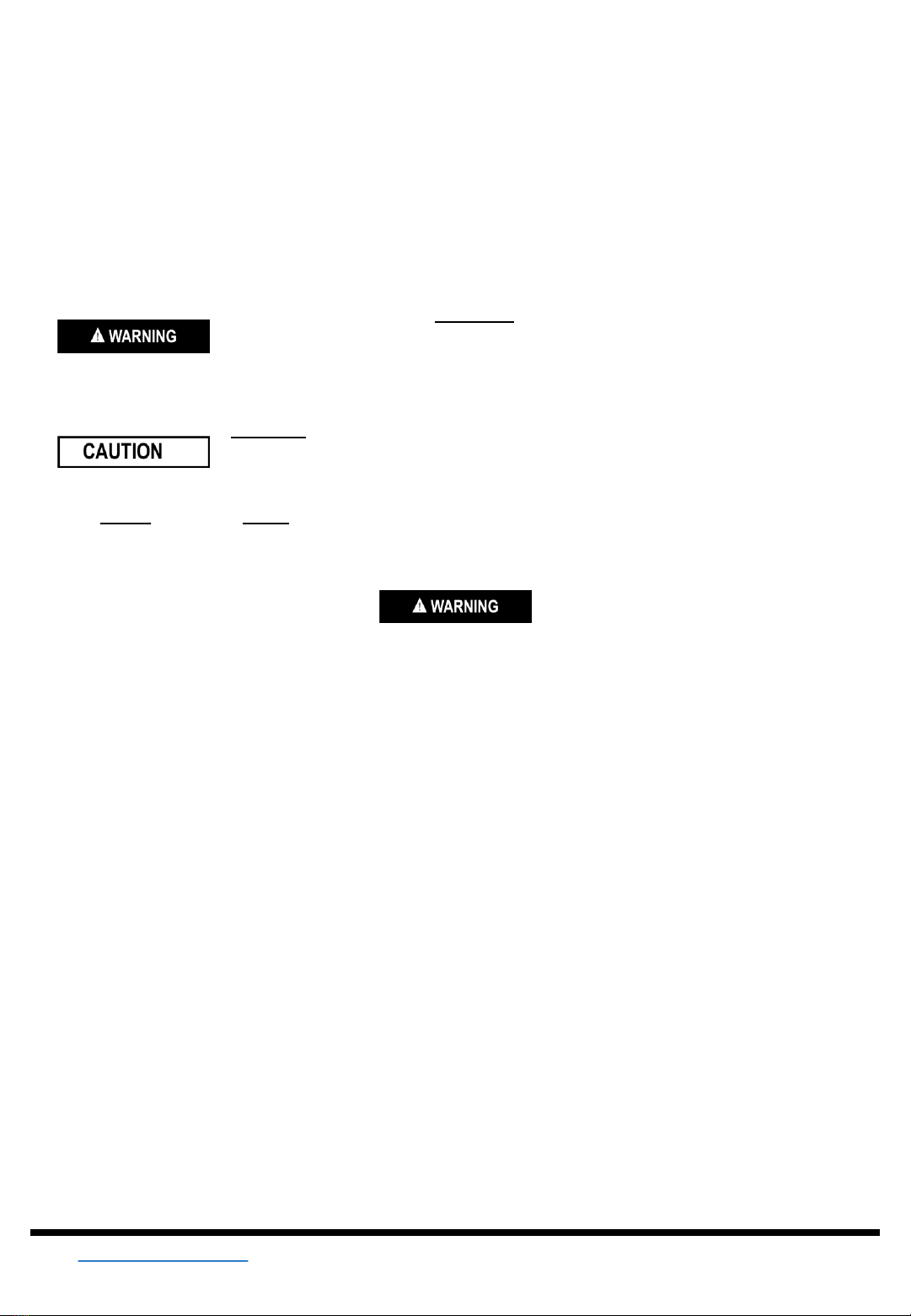
WARNING! Read and understand all instructions before using this device. The operator must follow
basic precautions to reduce the risk of personal injury and/or damage to the equipment.
Keep this manual for safety warnings, precautions, operating or inspection and maintenance instructions.
Information which is particularly important is distinguished in this manual by the following notations:
FAILURE TO FOLLOW WARNING INSTRUCTIONS COULD RESULT IN
SEVERE INJURY OR DEATH TO THE OPERATOR OR PASSENGER, A
BYSTANDER OR A PERSON INSPECTING OR REPAIRING THE PRODUCT.
CAUTION INSTRUCTIONS ARE PROCEDURES TO PREVENT DAMAGE TO
THE VEHICLE OR INJURY TO THE OPERATOR OR PASSENGER, A
BYSTANDER OR A PERSON INSPECTING OR REPAIRING THE PRODUCT.
A NOTE provides key information to make procedures easier or clearer.NOTE:
IMPORTANT RULES FOR SAFE OPERATION
1. This vehicle is not licensable. IT IS NOT TO BE OPERATED ON ANY PUBLIC ROAD, STREET,
HIGHWAY, PARKING LOT, SIDEWALK, OR ALLEY. To do so would be in violation of local law. This vehicle
may be operated only on private property and upon areas approved by local law. Avoid operating this
vehicle in any area with stationary objects that the vehicle could travel under. Do not ride in areas where
other recreational vehicles are being operated. Be respectful of landowners and the environment.
2. This vehicle should NEVER be operated indoors. The exhaust from the engine contains carbon monoxide,
which is a tasteless, odorless, and poisonous gas.
3. Unless otherwise specified in this manual, all screws, nuts, and bolts must be kept tight to ensure that the
vehicle is in safe operating condition. The engine must be kept free of all dirt and other accumulations,
paying particular attention to throttle linkage area.
4. The tire pressure should be checked prior to each use. The recommended inflation pressure is the
maximum tire pressure as printed on the tire’s sidewall. IMPROPER TIRE PRESSURE MAY CAUSE
INSTABILITY AND MAY PREVENT PROPER BRAKING OR STEERING.
5. Modifications of this vehicle or removal of any original equipment or safety decal may render the vehicle
unsafe or illegal. NEVER REMOVE ANY PROTECTIVE GUARDS, BELT GUARDS, OR SEAT BELTS.
These devices are for operator/passenger/service provider’s protection. If any guards are removed for
maintenance or servicing of the vehicle, ensure that they are secured in place prior to operating the
vehicle.
6. THE VEHICLE SHOULD NEVER BE STARTED WITHOUT FIRST CHECKING TO SEE THAT THE
THROTTLE IS IN IDLE POSITION. Do not start engine without verifying proper function of the throttle.
Never attempt to start this vehicle without having the operator seated in the proper position. When starting
with the operator in the seat, the operator should have their left foot on the brake.

V 1.48839615
For technical questions call: 1-800-665-86854
7. This vehicle is not designed or intended for racing, or any other form of competition.
8. The operator’s ability to operate this off-road vehicle safely is largely dependent upon the operator’s ability
to exercise proper judgment. An operator also must not be too small or too large for controlled operation.
The operator must be of sufficient age, understanding, mental capacity, and physical capability to safely
operate this vehicle. This vehicle should only be operated after mature, supervised instruction and sufficient
practice. Safe operation includes responsibility for the safety of a passenger (if any).
9. A DOUBLE SEAT VEHICLE IS DESIGNED FOR ONE OPERATOR AND ONE PASSENGER. No one
should ever attempt to ride on this vehicle without being seated, with the seat belt properly secured. For
double seat vehicles ridden without passenger, the passenger seat belt must be secure to prevent it from
getting caught up in operating components. Passengers must be of sufficient age, understanding, mental
capacity, and physical capability to act to protect himself/herself. ALWAYS FOLLOW THE RECOMMENDED
AGE RESTRICTION OF 16 YEARS FOR OPERATORS AND PASSENGERS.
10. The engine should be stopped when the vehicle is not in use.
11. The operator and passenger (if any) of this vehicle should always wear a helmet approved by agencies such
as Department of Transportation (DOT), Safety Helmet Council of America (SHCA), or Snell Memorial
Foundation (SNELL). Most off-road vehicle accident fatalities are due to head injuries. The operator should
also wear face shields or goggles, boots or closed-toe shoes, gloves, and other appropriate protective
clothing.
12. LOOSE CLOTHING, LONG HAIR, OR ARTICLES WORN BY ANY OPERATOR OR PASSENGER MUST
BE FULLY CONTAINED OR COVERED TO PREVENT THEM FROM POSSIBLY BEING CAUGHT IN
ROTATING PARTS OF THE VEHICLE OR THE SURROUNDING ENVIRONMENT WHILE RIDING.
FAILURE TO OBEY COULD ENDANGER THE PERSONAL SAFETY OF THE OPERATOR OR
PASSENGER.
13. DO NOT PLACE HANDS, FEET, OR ANY OTHER PART OF THE BODY OR ANY CLOTHING NEAR THE
ENGINE, MUFFLER, WHEELS, CHAIN AND OTHER ROTATING PARTS OF THE VEHICLE WHILE
RIDING OR RUNNING THE ENGINE. Caution must be used in performing required maintenance on or near
an operating engine. Special caution should be taken after the engine has been running, since the engine
and other drive components may be extremely hot.
14. Wet, slippery, rough, or steep terrain is potentially dangerous and may result in injury if proper caution in not
observed. Slow speeds are required to safely operate this vehicle under these conditions. The operator
must use mature judgment, skill, and experience to choose a speed suitable for terrain and riding
conditions.
15. The governor settings for this vehicle’s engine must not be tampered with, altered, or changed. The
governor is set by the engine manufacturer and limits the maximum speed of the engine (and vehicle) and
protects the engine from damage. Excessive speeds are potentially dangerous to the operator/ passenger,
and the engine.
16. Each time before using this vehicle, the fuel supply should checked. NEVER REFUEL THE FUEL TANK
WHILE THE ENGINE IS RUNNING OR WHILE THE ENGINE IS HOT. Do not refuel the tank in a closed
area such as a garage, while smoking, or in the vicinity of an open flame. Do not overfill the tank. There
should not be any fuel in the filler neck. Replace cap tightly to prevent spillage of fuel and potential fire
hazard. After filling tank, move the vehicle at least 15 feet away from the spot of filling before starting.

8839615V 1.4
Visit www.princessauto.com for more information 5
17. If the vehicle should start making unusual noise or vibrating abnormally, the engine should be stopped and
the spark plug wire disconnected. The vehicle should then be checked for damage. Excessive noise or
vibration is generally a warning of loose or worn parts.
18. When making repairs or adjustments to the vehicle which do not involve adjustments to the engine, the
spark plug wire must be disconnected and kept away from the spark plug to prevent accidental starting.
When working on or around, or when restarting engine, use extreme caution to avoid contact with the
muffler, cylinder head, or any other potentially hot area on or around the engine.
19. Always perform a pre-ride inspection before starting the engine. See the Pre-Ride Inspection section in this
manual.
20. When storing the vehicle, it must be kept in a place where gasoline fumes will not reach an open flame or
spark. For long period storage, such as for winter, the fuel tank should be drained in an open, cool area. The
engine must be allowed to cool before storage in any enclosure. Read and keep all printed material supplied
with this vehicle. If any printed material is unclear, contact the manufacturer or distributor.
21. NEVER OPERATE OR RIDE IN THIS VEHICLE WHILE UNDER THE INFLUENCE OF ALCOHOL,
DRUGS, OR MEDICATION OF ANY KIND. SUCH OPERATION COULD BE DANGEROUS TO YOURSELF
AND/OR OTHERS.
22. Always slow down when turning. High speed turning may cause loss of control, possible turnover of the
vehicle, and/or possible injury to the operator or passenger.
23. While making a turn, knobby tires may increase the risk of loss of control. ALWAYS SLOW DOWN! A
collision or rollover can occur quickly, even during routine maneuvers such as turning and riding on a hill or
over obstacles.
24. DO NOT RACE, JUMP, PERFORM "STUNT" RIDING, “DONUTS”, OR "SPIN OUTS" WHEN OPERATING
THIS VEHICLE. THIS VEHICLE IS NOT DESIGNED OR INTENDED FOR SUCH OPERATION.
25. This manual, along with the other supplements provided with your vehicle, provide guidelines for the
assembly, maintenance, and operation of this vehicle and is not intended as a service manual.
26. Assembly, maintenance, and/or repair of this vehicle should only be performed by persons of sufficient
mechanical skill, experience, and judgment (such as outdoor equipment dealers, motorcycle dealer/shops,
or small engine dealers) so that no unsafe condition or modification is made.
27. Always use extreme caution when starting the engine. Avoid touching the engine, muffler, or drive
components. These areas could cause burns on contact.
28. The battery contains sulfuric acid and must not come in contact with skin, eyes, or clothing since this will
cause severe burns possibly causing disfigurement. Also, battery may generate explosive gases and must
not be exposed to sparks, flame, cigarettes, or anything flammable or an explosion may result causing
severe injury. Protective gloves and face protection must be worn when servicing the battery.
29. ANY OPERATOR OR PASSENGER UNDER 18 YEARS OF AGE MUST ALWAYS BE APPROPRIATELY
SUPERVISED BY AN ADULT AT ALL TIMES WHILE OPERATING THE VEHICLE.
30. Operating this vehicle requires skills acquired through practice over a period of time. Take the time to learn
the basic techniques well before attempting to operate the vehicle.
31. Operate only on safe and familiar terrain. Avoid loose gravel and rocks. Be careful on wet surfaces and
allow for extra braking distance.

V 1.48839615
For technical questions call: 1-800-665-86856
BASIC FEATURES
9. Spare Tire
1. Engine Cover
2. Rearview Mirror
4. Front Turn Indicator
5. Front Bumper
3. Headlight
7. Front Tire
11. Rear Tire
8. Seat
Fig. 1
6. Front Wheel Hub
10. Shifter
17. Utility
Container
Bracket
16. Utility
Container
Hasp
15. Utility Container
(not for fuel)
18. Spare Tire
Mounting
Bracket
12. Steering Column
19. Rear Turn
Indicator
14. Rear Wheel Hub
13. Brake Indicator
Fig. 2
8839615V 1.4
Visit www.princessauto.com for more information 7
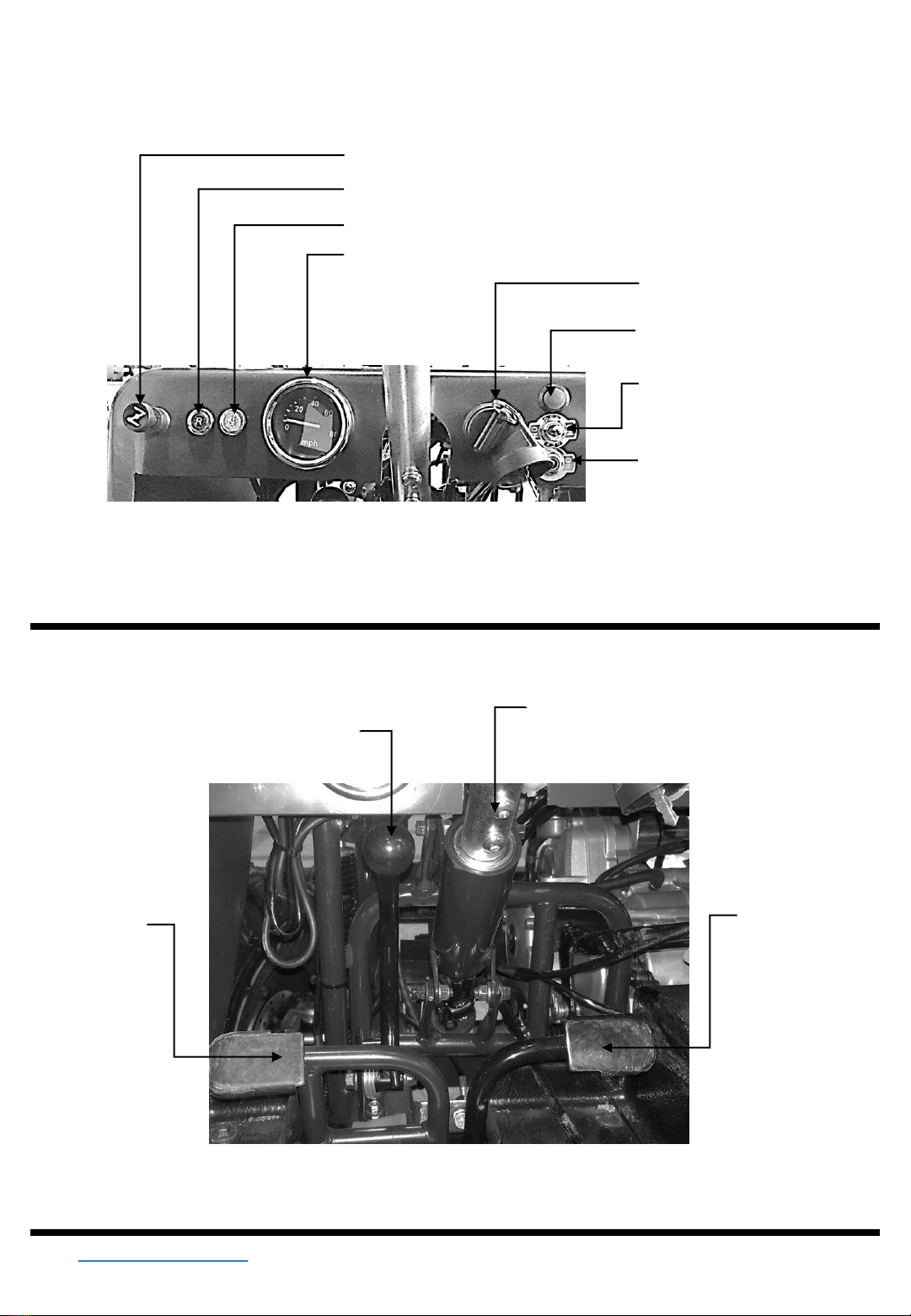
20. Keyed Ignition
Switch
21. Horn Button
22. L/R Turn Signal
Switch
23. Headlight
Switch
24. Choke Lever
25. Reverse Indicator
26. Neutral Indicator
27. Speedometer
Fig. 3
BASIC FEATURES
28. Steering Column
29. Accelerator
Pedal/Throttle
31. Brake
Pedal
Fig. 4
30. Parking Break

V 1.48839615
For technical questions call: 1-800-665-86858
UNPACKING AND ASSEMBLY
Step Description
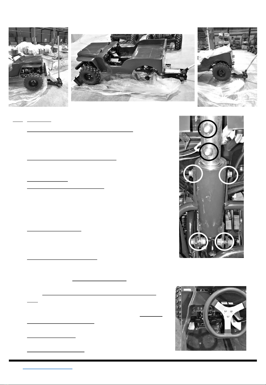
1. Your ATV is shipped on a metal frame and
covered with a cardboard top (Fig. 5).
2. Remove the plastic straps, and cardboard top
(Fig. 6)
3. Remove the bolts that hold the upper
shipping frame to the lower shipping frame,
then remove and discard the upper shipping
frame.
4. Remove the wire that is fastening the wheels
to the frame.
5. Move the wheels aside to a location that is
not in the way.
6. Remove the cardboard that surrounds the
plastic wrap, then remove the first layer of
plastic wrap. (Fig. 7)
7. Remove all of the loose parts that are packed
within the Utility Vehicle and along the sides
of the shipping crate and place them neatly
away from the shipping crate so they are not
in the way.
8. While the frame is still under the Utility
Vehicle, use a jack and jack stands to raise
the front of the vehicle to a height which will
allow the tires to be mounted to the hub. (Fig.
8)
Note: It is possible, but not recommended, for two
people to lift both the back and front of the
vehicle while a third places the wheels on.
9. Mount the front tires onto the wheel hubs,
and using four of the supplied M10 self-
locking nuts for each wheel, tighten the nuts
(Fig. 8) with a 14mm deep well socket
wrench.
Fig. 7
•Unpacking and assembly should be done on a clean, well-lighted, and LEVEL surface.
•Allow sufficient workspace so the packaging and other parts may be easily organized.
•Assembly should only be performed by a competent adult who is familiar with basic safety and tools required
for assembly.
•Review this assembly procedure and familiarize yourself with the BASIC FEATURES section in this manual
before attempting assembly,
•If you have questions, or are missing components, contact us at 1-800-665-8685.
TOOLS NEEDED: ½ Ton Jack, and Jack Stand; 14mm deep-well, 12mm, and 8mm sockets; socket wrench, and
torque wrench; 14mm, 12mm, and 8mm box end wrenches; Phillips #2 screwdriver, 4mm & 5mm Hex Keys;
Fig. 5
Fig. 6
8839615V 1.4
Visit www.princessauto.com for more information 9
UNPACKING AND ASSEMBLY
Step Description
10. Lower the front end and chock the front wheels in the front to
prevent the vehicle from rolling forward. Use a jack and jack
stands to raise the rear of the vehicle to a height which will allow
the tires to be mounted to the hub (Fig. 9).
11. Mount the rear tires onto the wheel hubs, and using four of the
supplied M10 self-locking nuts for each wheel, tighten the nuts
(Fig. 10) with a 14mm deep well socket wrench.
11. Lower the rear end and remove the chocks.
12. Secure the steering column in place If the four nuts and bolts
have not been assembled (Fig. 11, white circles) , use a 12mm
socket wrench and a box end wrench and the supplied four M8
x 20mm bolts and nuts to secure it in place. Otherwise, mount
the adjustable height steering tube using a 5mm hex key using
the screws (Fig. 11, black circles) on the steering column.
13. Mount the steering wheel using a Philips head screwdriver and
the supplied three M6 x 16mm button head screws (Fig. 12). Be
sure that the flat on steering wheel is on the bottom and the
wheels are pointing straight. (Fig. 12)
14. Adjust the steering wheel height using a 5mm hex key to
remove the screws (Fig. 11, black circles) and reinstall at a
comfortable height, be sure both screws are engaged.
15. Put the transmission shift lever into the neutral position (see the
OPERATING - SHIFTER section in this manual).
16. Gently roll the vehicle until it is completely off of the shipping
crate (either forward or reverse) , and remove the shipping crate
for disposal.
17. Using a 14mm deep well socket and torque wrench, tighten the
nuts on each of the wheel hubs to a minimum of 29 N-m (21 ft-
lb). Be sure to cross-tighten the nuts.
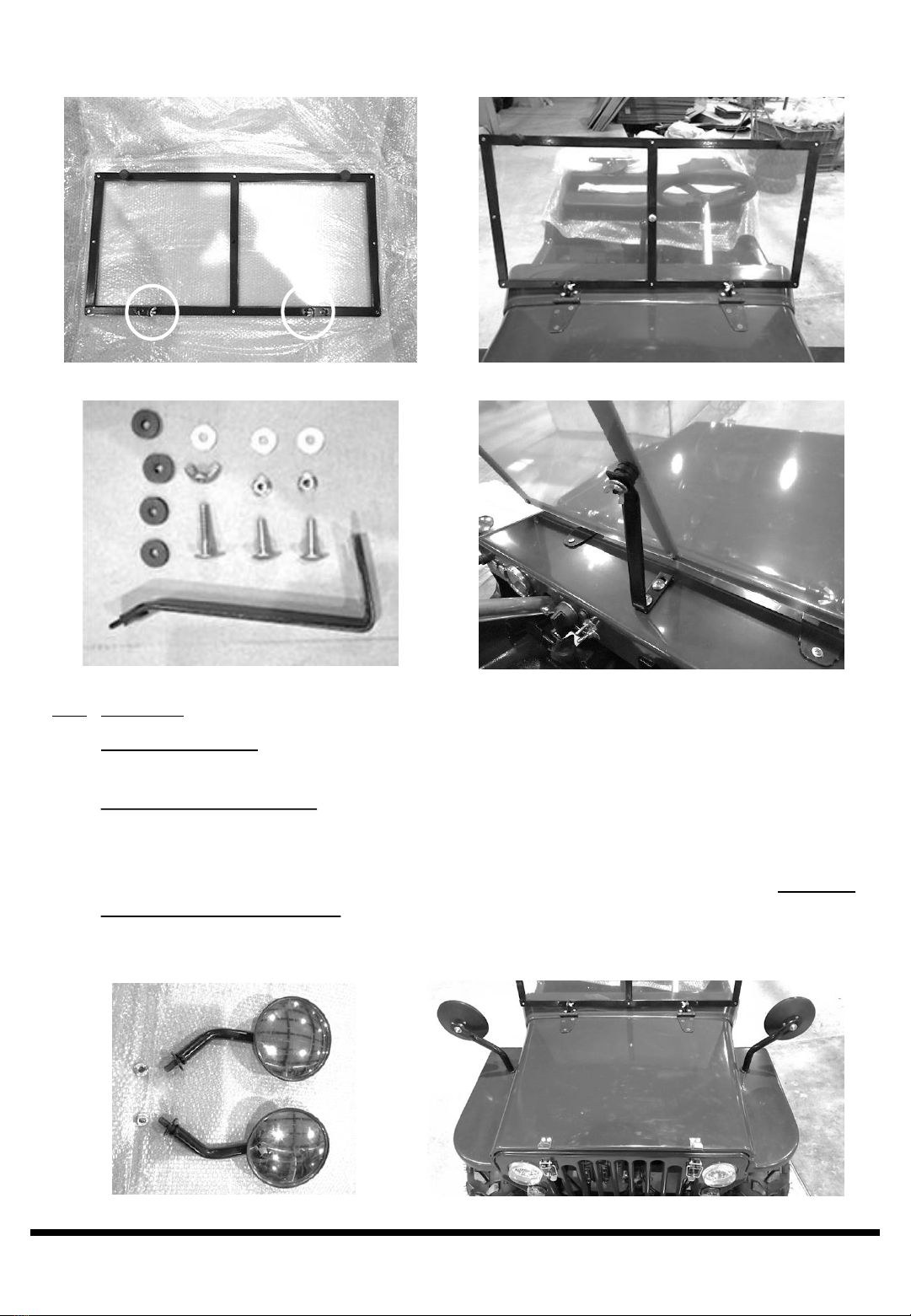
18. Unpack the windshield and remove the two M6 x 25mm button
head screws and M6 wing nuts (Fig. 13, Circled).
19. Remove the protective film from both sides of the windshield.
Fig. 11
Fig. 12
Fig. 8 Fig. 9 Fig. 10
V 1.48839615
For technical questions call: 1-800-665-868510
UNPACKING AND ASSEMBLY
Step Description
19. Attach the windshield by placing it onto the brackets and fasten it with the two M6 x 25mm button head
screws and M6 wing nuts (Fig.14).
20. Attach the windshield bracket (Fig. 15) by using a Philips screwdriver and a 8mm socket and socket
wrench to attach the windshield bracket as shown in Fig. 12 with the two M6 x 25mm Philips button head
screws, flat washers and nuts.
21. Use the M6 x 35mm Philips button head screw, rubber spacers, flat washer, and wing nut to secure the
windshield in the upright position as shown in Fig. 16. Note: The rubber washers should be between the
bracket and the windshield, and the flat washer should be behind the wing nut on the inside of the
vehicle.
Fig. 13 Fig.14
Fig.15 Fig.16
Fig. 17 Fig. 18
8839615V 1.4
Visit www.princessauto.com for more information 11
Step Description
22. Install the rearview mirrors. Locate the rearview mirrors, and remove the M10 nuts (Fig. 17). With the
flat washer on top side of the wheel well, place the driver’s side mirror (Fig. 17, Bottom) into the hole in
the wheel well on the drivers side. Be sure that the bolt on the mirror passes through the Mirror Bracket
underneath, if necessary, align the bracket with the hole. Use the M10 nut to hand tighten the mirror in
place. While holding it in the correct position (Fig 18), and using a 14mm socket and socket wrench,
tighten the M10 nut. Repeat this step for the passenger side mirror (Fig. 18, Top).
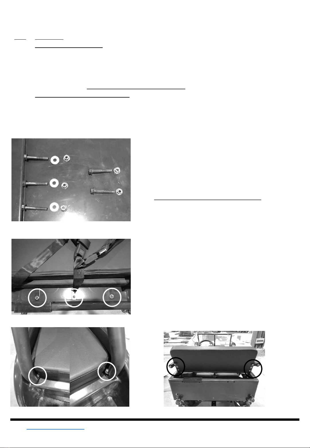
23. Attach the seat cushion and handrails to the vehicle body. Remove the five M8 x 50mm shoulder bolts,
self locking nuts, and three flat washers (Fig. 19) where the seat is to be installed. Place the seat
cushion onto the body and install the three M8 x 50mm shoulder bolts at the back of the seat as shown
in circled areas of Fig. 20 with the flat washer and bolt on the top, nut underneath, DO NOT TIGHTEN.
Next, use the remaining two M8 x 50mm shoulder bolts and nuts (Fig. 19, Right) with the nut
UNPACKING AND ASSEMBLY
underneath, DO NOT TIGHTEN. Next, secure the rear of
the armrest with the uppermost screw on the seat back
using a 4 mm hex key (Fig. 22, circled). Once the rear of
the armrest is tightened, use a 12mm socket, socket
driver, and 12mm box end wrench to secure the front of
the handrails (Fig. 21) and the rear of the seat cushion
as shown in circled areas of Fig. 21.
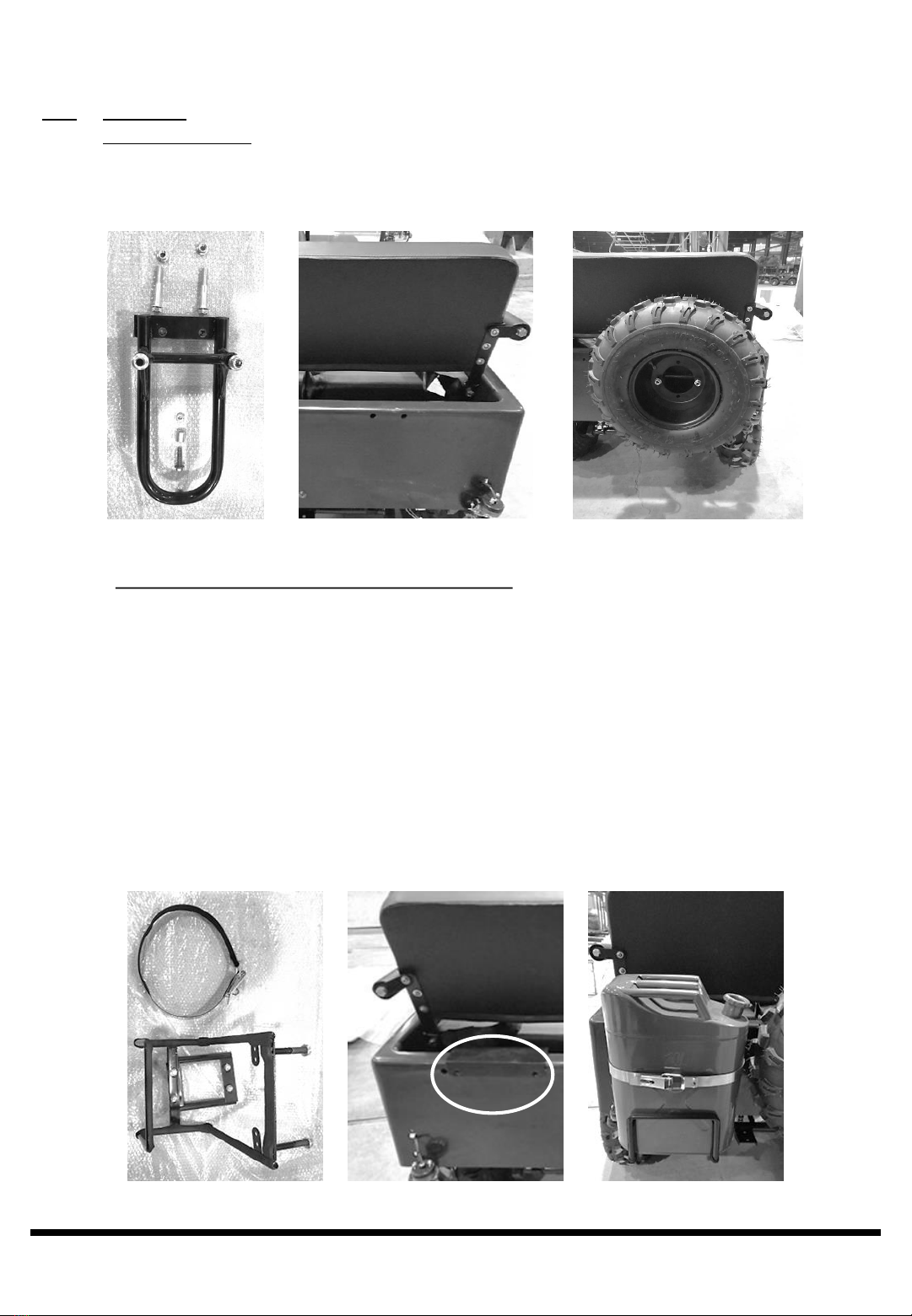
24. Install the spare tire bracket and spare tire. Locate the
spare tire bracket (Fig. 23), the two M8 x 65mm shoulder
bolts and self locking nuts, the one M6 x 30mm bolt and
nut, and the hollow 16mm x 16mm x 8.5mm
stanchion/spacer. Place the bracket on the passenger
side rear of the vehicle body (Fig.24), align the holes and
insert the two M8 x 65mm shoulder bolts and hand
tighten the self locking nuts. Put the stanchion/spacer
between the frame and the body on the bottom of the
bracket, then insert the M6 x 30mm bolt through the
bracket, stanchion/spacer and body. Tighten the M8 x
65mm bolt and nuts using a 12mm socket and socket
wrench and a 12mm box end wrench, then tighten the
M6 x 30mm bolt and nut using a 8mm socket and socket
wrench and 8mm box end wrench.
Fig. 19
Fig. 20
Fig. 21 Fig. 22
V 1.48839615
For technical questions call: 1-800-665-868512
UNPACKING AND ASSEMBLY
Step Description
25. Mount the spare tire onto the spare tire bracket as shown in Fig. 25 by removing the two M10 self
locking nuts, placing the spare tire onto the studs, and tightening the M10 self locking nuts using a
14mm socket and socket wrench.
Fig. 23 Fig. 24 Fig. 25
26. Install the utility container bracket and utility container. Locate the utility container bracket quick release
hasp and band (Fig. 26), and body brace which may already be on the body, (Fig. 27, circled). Attach
the quick release hasp and band to the utility container bracket with the Philips screws and nuts on the
band and tighten using a Philips screwdriver and a box end wrench. Place the body brace on the body
and align the holes on the vehicle body behind the drivers side, as shown in Fig. 27, circled. Remove
the M10 self locking nuts from the studs and remove the four M8 x 20mm panhead screws and self
locking nuts from the lower support bracket. Insert the M10 studs on the utility container bracket through
the body brace and hand tighten the M10 nuts. Place the bottom brace of the utility container bracket
onto the bottom of the bracket and attach to the body using the four M8 x 20mm panhead screws.
Tighten these using a Philips screwdriver and 12mm box end wrench. Tighten the two M10 nuts using a
14mm socket and socket wrench. Place the utility container onto the bracket and secure using the quick
release hasp as shown in Fig. 28.
Fig. 26 Fig. 27 Fig. 28

8839615V 1.4
Visit www.princessauto.com for more information 13
Fig. 29 Fig. 30
UNPACKING AND ASSEMBLY
Step Description
27. Install the brake lights and rear turn indicators to the vehicle as shown in Fig. 30 (Red light on bottom)
by removing the two M6 self locking nuts shown in Fig. 29, inserting the studs through the holes on the
body, and tightening the M6 self locking nuts using an 8mm socket and socket wrench. Remove the
plastic protective film on both the turn and brake indicators. Plug the lights into their respective plugs
and use the included plastic wire ties to secure the wires against the frame and to keep them from
hanging down (Fig 31). Repeat this step for the opposite side brake and turning indicator.
BATTERY INSTALLATION AND CHARGING
Face Shield
Goggles
Rubber Gloves
Vinyl Apron
REQUIRED PERSONAL PROTECTIVE EQUIPMENT
WARNING! The following procedure is VERY DANGEROUS and should be performed with the utmost care and
attention. Always wear protective personal equipment including eye wear, face shield, apron, and rubber gloves.
Have a running water source available should electrolyte come in contact with skin or eyes.
KEEP ALL CHILDREN AWAY FROM THE AREA WHILE THIS PROCEDURE IS BEING PERFORMED.
Fig. 31

V 1.48839615
For technical questions call: 1-800-665-868514
BATTERY INSTALLATION AND CHARGING
POISON -CAUSES SEVERE BURNS
The electrolyte contains sulfuric acid. Avoid contact with skin, eyes, or clothing.
To prevent accidents, neutralize excess acid with baking soda and rinse empty container with water.
In case of:
SKIN CONTACT: rinse with water, remove and wash wetted clothing.
INHALATION OF ACID MIST: inhale fresh air, seek advice of a medical doctor.
CONTACT WITH THE EYES: rinse under running water for several minutes, seek immediate medical
attention.
SWALLOWING or INGESTION: drink large quantities of milk or water, followed by milk of magnesia,
vegetable oil, raw beaten eggs, or swallow activated carbon, do not induce vomiting. Call a poison
control center or doctor immediately.
KEEP OUT OF REACH OF CHILDREN.
Preparing the battery
Note: This battery is 12VDC. The battery model number is YTX9A-BS. For
recommended charging times, see the section labeled CHARGING THE BATTERY in
this manual.
Step Description
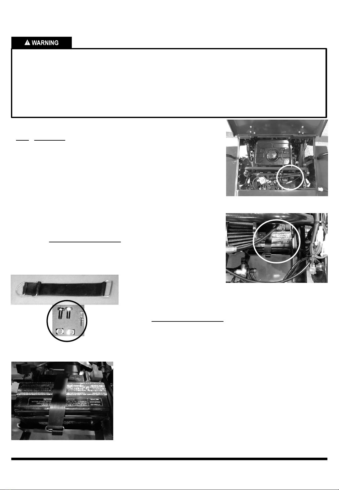
1. Prepare the battery by placing it on a flat surface. Remove the foil sheet that
covers the filler port on the top of the battery. See Fig. 32
2. Wear personal protective equipment including eye protection, face shield,
apron, and rubber gloves for the following steps. Remove the cap strip from
the electrolyte container and put the strip aside – you’ll use this later as the
battery sealing plug (Fig. 33). Place the electrolyte container, sealed top
down, into the filler ports of the battery. Hold the container level and push
down to pierce the six in-line openings of the container. You’ll see air bubbles
as the ports fill. Do not tilt the electrolyte container. Keep the container in
place for 20 minutes or longer until it empties completely (Fig.33) Use the
supplied pushpin (Fig. 39, circled) to poke a hole in the top of each container
to make it drain faster. If no air bubbles are coming up from the filler ports, or
if one or more container cells haven’t emptied completely, tap the container a
few times.
3. When the electrolyte container is completely empty, carefully remove it from
the battery. Neutralize any excess acid with baking soda and rinse the empty
electrolyte container with water before discarding the empty container. Ensure
the discarded container is inaccessible to children and animals.
4. After filling the battery, loosely place the cap strip over the battery cell holes,
(Fig. 34) and let the battery stand for at least 30 minutes BEFORE charging.
This allows the electrolyte to penetrate the plates for optimum performance
while ensuring longer battery life.
5. Seal the battery by pressing down on the cap strip before charging.
Fig. 32
Fig. 33
Fig. 34

8839615V 1.4
•To avoid possibility of an EXPLOSION, always connect battery cable in the order specified: RED first;
BLACK last.
•Charging the battery while it is in the vehicle is NOT RECOMMENDED.
•Do NOT charge a battery if its temperature is below 3°C as the electrolyte may have frozen.
•If battery gets hot to the touch, discontinue charging and allow battery to cool down.
•Batteries contain sulfuric acid which is POISONOUS and can cause SEVERE BURNS. See the additional
warnings at the beginning of BATTERY INSTALLATION AND CHARGING section above.
•Always use PERSONAL PROTECTIVE EQUIPMENT including eye wear, face shield, apron, and rubber
gloves when working around battery acid.
•Lead acid batteries generate oxygen and hydrogen. These gases can be explosive. Charge the battery in a
well ventilated area.
•DO NOT smoke around batteries. Remove any source of ignition such as an open flame or a device like a
heater from the area. Sparks may ignite the gas. An exploding battery can cause SERIOUS INJURY OR
DEATH.
Charging the battery
Step Description
1. Ensure the battery charger is OFF. Connect the red positive (+) cable to the red
positive (+) pole of the battery, as shown in Fig. 35
2. Connect the black negative (-) cable to the black negative (-) pole of the battery,
as shown in Fig. 36
3. Set the battery charger to 12VDC output before switching it on. Normal
Charging time for the battery @ 0.9 Amps for 5 ~ 10 hours. Quick charging the
battery is NOT recommended. The quick charge rate for the battery is 9A for 1/2
hour. Switch the charger on.
4. After charging, turn the battery charger off and unplug it. Disconnect the clamps
from the battery, positive (+) cable first, negative (-) lead last.
5. A normal, fully charged battery will have a reading of >12.4VDC. After the initial
charge, voltage may be up to 13.8VDC
TOOLS NEEDED: Battery charger for lead acid batteries rated 12VDC, 1A (minimum)
•This battery is a permanently sealed type. Once the caps have been used to
seal the battery, DO NOT loosen or remove the caps.
•DO NOT add water or electrolyte to the battery.
•Keep metal tools and jewelry away from batteries (to prevent short circuits).
•When handling and installing the battery, make sure that metal objects do not
fall across the terminals.
•Inspect the battery for any defective cables, corroded cable connectors,
corroded/broken battery terminals, cracked cases or covers, etc. before
installation.
Fig. 35
Fig. 36
Visit www.princessauto.com for more information 15
V 1.48839615
Step Description
1. Open the Engine Cover and locate the battery tray underneath the
air filter and next to the engine transmission on the driver’s side
(Fig. 37 and Fig.38, circled).
2. Gently place the battery into the battery tray, and using the rubber
battery strap (Fig. 39, Top), secure the battery in place (Fig. 40).
3. Connect the red positive (+) cable to the positive (+) pole of the
battery. Use an M6 x 12mm bolt and nut (Fig. 38, circled) which is
supplied with the battery using an M10 box end wrench. ENSURE
THE WRENCH DOES NOT TOUCH THE NEGATIVE TERMINAL
AND DO NOT OVER TIGHTEN.
4. Connect the black negative (-) cable to the negative (-) pole of the
battery. Use an M6 x 12mm bolt and nut (Fig. 39, circled) which is
Installing the battery
•When INSTALLING the battery, always connect the POSITIVE (+) TERMINAL FIRST, and the NEGATIVE (-)
TERMINAL LAST.
•When DISCONNECTING the battery, terminals should be disconnected in the REVERSE ORDER, negative
terminal first, then positive.
•Always use the proper wrench size when tightening cable clamp nuts.
•Do not use excessive force when tightening connections to the battery terminals.
•Never allow both terminals to simultaneously make contact with an item, including yourself.
TOOLS NEEDED: 8mm box end wrench
Fig.37
Fig.38
Fig.40
supplied with the battery using an M10 box end wrench. ENSURE
THE WRENCH DOES NOT TOUCH THE POSITIVE TERMINAL
AND DO NOT OVER TIGHTEN.
5. The use of petroleum-jelly (Vaseline) is not necessary to use on the
battery terminals, but there is no disadvantage in using it. Smear
lightly on the terminals. Do not use grease.
6. Move the terminal covers over each terminal to protect them from
dust, debris, and water.
For technical questions call: 1-800-665-868516
Fig.39
8839615V 1.4
For technical questions call: 1-800-665-868517
FUEL AND OIL
•Gasoline is extremely FLAMMABLE and can be EXPLOSIVE under certain conditions, creating the potential
for serious burns. Always keep gasoline out of the reach of children.
•Turn the ignition switch to “OFF”. The fuel tank should never be filled while the engine is running or while the
engine is hot.
•DO NOT FILL TANK IN A CLOSED AREA such as a garage, while smoking, and away from any source of
flame or sparks; this includes any appliance with a pilot light.
•DO NOT OVERFILL the tank. If the tank is filled completely to the top, heat may cause the fuel to expand
and overflow through the vents in the tank cap. There should not be any fuel in the filler neck.
•Replace cap tightly to prevent spillage of fuel and potential fire hazard.
•After filling the tank, move the vehicle at least 15 feet away from the spot of filling before starting.
Use only regular unleaded gasoline with an octane rating of 90 or higher. Using a lower rated fuel may result in
poor performance and a shorter life-span of the engine.
Fuel can damage paint and some types of plastic. Be careful not to spill fuel when filling your fuel tank.
FUEL SELECTION
The proper fuel is very important for the engine. Use only regular unleaded gasoline with an octane rating of 90
or higher. Ensure that there is no dust, dirt, or water which has mixed in the fuel.
FUEL TANK CAPACITY
The fuel tank capacity is 4 liters (1 US Gallon)
REFUELING
1. Place the engine on a level surface before fueling.
2. Shut off the engine.
3. Both the passenger and driver should exit the vehicle and stand aside prior to filling.
4. Remove the fuel tank cap.
5. Slowly pour fuel into the tank, DO NOT OVERFILL.
6. Close the tank cap securely.
NOTE: The utility container is intended only for storage and transport of feed, attractants, water, fluids and other
outdoor products. It is NOT a portable fuel container and does not comply with ASTM, EPA, ARB, CSA, or other
federal, provincial, state, or local regulations.
New and used oil could be hazardous.
•Children and pets may be harmed by swallowing new or used oil.
•Continuous contact with used oil can cause skin cancer in laboratory animals.
•Brief contact with the used oil may irritate the skin.
•Keep new and used oil away from children and pets. To minimize your exposure to used oil, wear a long-
sleeve shirt and moisture-proof gloves (such as dish washing gloves) when changing oil. If oil contacts your
skin, wash thoroughly with soap and water. Launder any clothing or rags if wet with oil.
•Recycle or properly dispose of used oil.

V 1.48839615
For technical questions call: 1-800-665-868518
Failure to use the correct oil could harm the engine. Be sure to use the oil specified in this section.
•Running the engine without an adequate amount of engine oil could cause engine overheating and severe
engine damage.
•Always check the amount of engine oil before starting the engine, and follow the maintenance schedule.
•Allow the Engine Oil to Circulate Before Riding.
•Allow enough idling time after warm or cold engine starting. This allows the lubricating oil to reach all critical
engine components.
ENGINE OIL
Your 125cc ATV has a four-stroke engine. The engine
has been filled with SAE 15W/40 (mineral based) oil
prior to shipment and is recommended for the best
performance and lubrication of the engine. SAE15W/40
is suitable for use between temperatures of +40°C and
-10°C, however because viscosity varies with regions
and temperatures, if you wish to use another viscosity,
select a suitable oil as described in the chart above.
Initial oil change should be performed after 10 hours of
operation. Thereafter change oil every 30-50 hours.
ENGINE OIL CAPACITY
The engine oil capacity is 0.9 liters (1 US Quart)
CHECKING THE ENGINE OIL
1. Park the vehicle on level ground and turn the
wheels to the left. Turn the engine off and allow it to
sit for a few minutes.
2. Remove the dip stick located behind the passenger
side front wheel on the engine crankcase (Fig. 42).
3. Wipe the dipstick dry with a clean cloth.
4. Reinstall the dipstick completely.
5. Remove the dipstick and check the oil level.
6. Oil level should be in between the lower index line
and upper index line marks on the dipstick (Fig. 41).
7. Add the recommended oil if it is below lower mark
on dipstick. Do Not fill above upper mark.
8. Reinstall the dipstick
Lower index line
(Below this add oil)
Upper index line
(Do not fill above this mark)
Fig. 41 Fig. 42
8839615V 1.4
Visit www.princessauto.com for more information 19
AIR FILTER
NEVER RUN THE ENGINE WITHOUT THE AIR FILTER in place.
•Operating the engine without the air filter in place will allow dust and debris to enter the engine resulting in
severe engine damage.
AVOID getting the air filter wet when in operation or while washing the vehicle.
DO NOT use pressurized air to clean the air filter.
A dirty air cleaner element will cause starting difficulty, power loss, engine malfunctions, and shorten engine life
extremely.
Always keep the air cleaner element clean. Examine carefully the element for tears before and after cleaning it.
Replace the element with a new one if it is torn.
Clean or replace the air cleaner element more often in dusty environments.
Be sure to position the air cleaner element properly when reinstalling the air filter. Unfiltered air will bypass the
air cleaner element if the element is not positioned properly and will result in rapid engine wear.
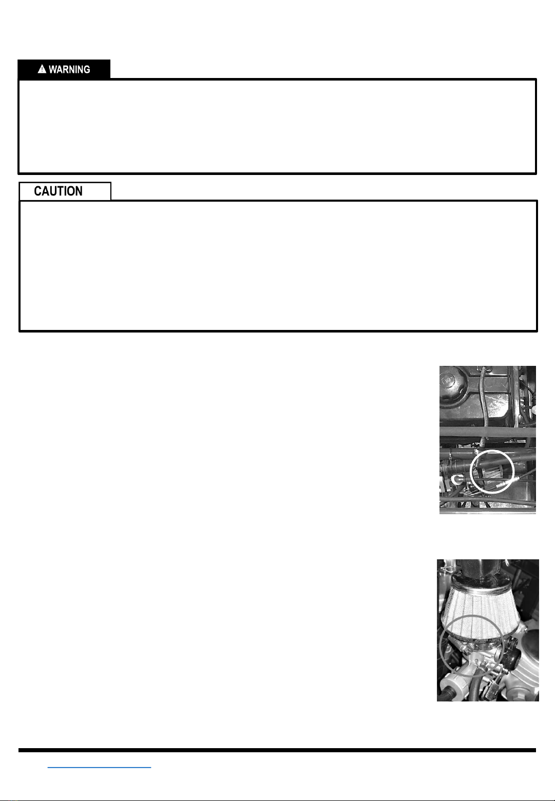
AIR FILTER CLEANING
The air filter should be serviced at least once every 30 days of use. Service the filter
more frequently when using the vehicle in unusually wet, muddy, or dusty
environments. To service the filter:
1. Open the engine cover and locate the air filter (Fig. 43, circled) which is located on
the carburetor, next to the choke mechanism. loosen the clamp (Fig. 44, circled)
using a flathead screwdriver and pull the air filter off of the carburetor.
2. Gently tap the filter against the inside of a trash can to remove the external dirt
particles. Tap it so the dirty side is towards the surface being tapped.
5. Spray the filter with a filter cleaner solution and allow it to soak in for about 10
minutes. Do not let it dry.
6. Rinse the filter with warm water, clean side to dirt side, to flush out the dirt. Do not
use high pressure sprayers or hose nozzles as they can damage the filter. After
rinsing, gently shake off excess water.
7. Allow the filter to dry. Placing it in a warm area or in sunlight will help to speed up
the drying process. Do not use any direct heat source (heat gun, hair dryer, etc.)
as it may damage the filter.
8. Wipe any overspray off of the filter lid, and base and re-install the filter after
inspecting it for any damage.
Fig. 43
Fig. 44
V 1.48839615
For technical questions call: 1-800-665-868520
SPARK PLUG
Improper installation of the spark plug could damage the engine.
•An overly tight or cross threaded spark plug will damage the threads of the cylinder head.
•Carefully turn the spark plug by hand into the threads. If the spark plug is new, tighten it with a wrench about
½ turn past finger tight. If you are reusing the old spark plug, tighten it with a wrench about 1/8 turn past
finger tight.
Do not allow dirt or debris to enter an open spark plug hole.
•Any dirt or debris that enters the spark plug hole will cause severe engine damage.
•Always cover the spark plug hole while the spark plug is out of the hole.
To maintain a proper functioning spark plug, keep the plug clean and free of carbon.
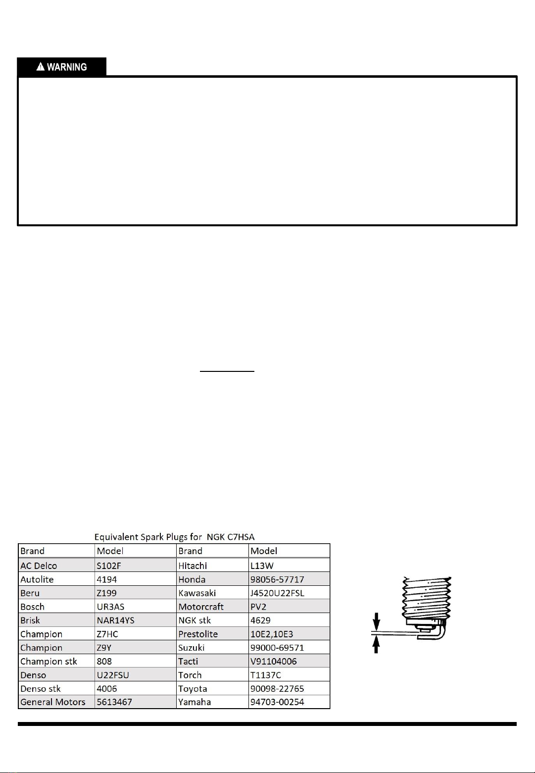
SPARK PLUG REMOVAL,
INSPECTION, REPLACEMENT
This vehicle uses a resistor-type spark plug. Improper
replacement spark plug selection may cause problems
with the ignition system, resulting in poor vehicle
performance. ONLY use the recommended spark plug
or equivalent as shown in the chart below. The spark
plug should be checked every 50 to 100 hours of use.
Recommended replacement spark plug: C7HSANGK
NOTE: ALWAYS thread a spark plug in as far as
possible with your fingers first when installing, then
tighten it with a wrench.
1. Disconnect the spark plug wire cap from the spark
plug.
2. Clean any dirt or debris from around the spark
plug.
3. Remove the spark plug using a plug wrench and
cover the spark plug hole.
4. Inspect the spark plug electrodes and the center
porcelain insulator for deposits, erosion, or carbon
fouling. If there is heavy erosion, replace the spark
plug. Otherwise, remove carbon from the plug
using a plug cleaner or wire brush. Clean the
center electrode by using a nail file to make it flat.
5. Using a feeler gauge, check and adjust if
necessary the electrode gap to ensure proper
ignition. The gap (Fig. 44) should be 0.24 - 0.28
inches (0.6~0.7mm).
6. Check to ensure the plug washer is in good
condition.
7. Thread the spark plug into the spark plug hole by
hand while ensuring it is not cross-threaded. Using
a plug wrench, tighten a NEW plug to ½ turn past
finger tight, or an OLD plug to 1/8 turn past finger
tight.
8. Reconnect the spark plug wire.
Fig. 44
This manual suits for next models
1
Table of contents
Popular Utility Vehicle manuals by other brands


Club Car
Club Car IQ PLUS 2008 Maintenance and service manual supplement

Makita
Makita DCU601 instruction manual

Razor
Razor Ground Force 300001-SL owner's manual

Clam
Clam POLAR TRAILER HD MAX TA 10813 manual

Land Pride
Land Pride 22081 Operator's manual

J&J Amusements
J&J Amusements King Scorpion Service manual

Cushman
Cushman SHUTTLE 2+2 Service & parts manual

E-ride Industries
E-ride Industries 2011 EXV2 owner's manual

Dynapac
Dynapac CA 250 Workshop manual

Ezytrail
Ezytrail STIRLING GT Setup guide

Coleman Powersports
Coleman Powersports SK100 Assembly instructions

STRUC MUTA
STRUC MUTA TRAILER KIP operating manual