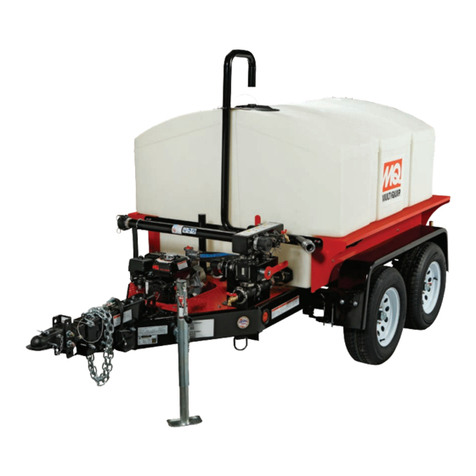
MULTIQUIP WTE5C Reference manual

Product Group: Date Issued: Service Bulletin No.
Bulletin Type
_____ Mandatory
_____ Information Only
_____ Recommended Change
Table 1. WTE5C/WTE5HP Axle Service Kit
Item
No. Part No. Description QTY. Remarks
1 29396-SK Assembly AxleTRLR70
Electric Service Kit 1Includes
items 2-8
2 19761 Splice Terminal 12
3 2540 Wire Butt Conector 16
4 29249 Axle, Hex Nut 9/16"-18
N-2 16
5 29248 Axle, Mount Screw 9/16"-
18 X 3" 16
6 29396
Axle, Electric Brake
Assy. 3,500 lb (1,587 kg)
Capacity
2
7 1662 Cable-Tie 8
8 49498 Instruction Sheet 1
234
7
1
WTE5C/WTE5HP
REPLACEMENT
AXLE INSTRUCTIONS
8
6
5
WTE5C/WTE5HP SERIES WATER TRAILERS — SERVICE BULLETIN WT20180925 — 09/25/18 — PAGE 1
Service Bulletin
WTE5C/WTE5HP Series Water Trailers
Parts Information
Water Trailer Models: WTE5C/WTE5HP
X
SERIAL NUMBER/VIN NUMBER
50022, 50024
50026 - 50028
50077 - 50083
50105 - 50117
50305 - 50308
50401 - 50406
50479 - 50484
50534 - 50539
S/N correspond to the last 5-digits of VIN
located on the trailer frame
10/01/18 WT20180925
Details
Problem:
a. A select number of water trailers were shipped with axle assemblies that do not meet with proper axle load
ratings (GAWR).
Solution:
a. Replace existing axles with proper rated axle assemblies.
Figure 1. Electric Axle Service Kit (TRLR70)

WTE5C/WTE5HP SERIES WATER TRAILERS — SERVICE BULLETIN WT20180925 — 10/01/18 — PAGE 2
NOTES

WTE5C/WTE5HP SERIES WATER TRAILERS — SERVICE BULLETIN WT20180925 — 10/01/18 — PAGE 3
NOTICE
Affected axles (2,470 lbs.) must be returned to the
vendor as follows:
Ship to: Dexter MWR, 1845 South 300 West, Salt Lake
City, UT 841115
Attention: B. Quigley
Use account number: XPO Logistics 640849505
Affected axles must be shipped to vendor within 30
days.

WTE5C/WTE5HP SERIES WATER TRAILERS — SERVICE BULLETIN WT20180925 — 10/01/18 — PAGE 4
SAFETY
PROCEDURE
Axle Removal
1. Place water trailer on firm and level ground (Figure 2). DO
NOT place trailer on soft or uneven ground. Soft or uneven
ground will not allow for secure placement of hydraulic jack
or jack stands.
Figure 2. Trailer Placement
2. Position a hydraulic jack behind the tire, using the frame
(only) as a lift or contact point.The use of a wood block
is acceptable to extend the height of the hydraulic jack.
NOTICE
Only qualified personnel with proper training should
perform this installation. Follow all shop safety rules
when performing this installation.
NOTICE
The following step-by-step procedures are provided to
assist in the removal and replacement of the tandem
electric axle assemblies used on the Multiquip Water
Trailer models: WTE5C and WTE5HP. Both axle
assemblies will be replaced.
NOTICE
Secure trailer in accordance with Job Hazard
Analysis (JHA) 20140618-002, Securing Trailer for
Maintenance/Repairs.
3. Raise the trailer until the tire is no longer contacting
the ground. The tire should be able to freely rotate
while maintaining a minimum clearance between the
ground and tire.
Figure 3. Jacking The Trailer
4. Next, place jack stands underneath the trailer frame.
5. Remove the tires (4) - break the wheel lug nuts (5) loose
with a ratchet (or breaker bar) and socket.
Figure 4. Removing The Tire
6. Save the lug nuts they will be used later.
7. Locate the wiring harnesses along the right and left
side of the trailer rails beneath the trailer frame.
NOTICE
DO NOT attempt to raise the trailer by jacking on
the axles or the suspension. This will cause damage
to the axles or suspension. ALWAYS place the jack
underneath the frame to prevent bending or deformation
of the axles or suspension.
WOOD BLOCK
HYD. JACK
FRAME
WTE5C/WTE5HP SERIES WATER TRAILERS — SERVICE BULLETIN WT20180925 — 10/01/18 — PAGE 5
8. Open the splice terminals (P/N 19761) and remove
the wires coming from the axle brakes as shown in
Figure 5.
Figure 5. Splice Terminals
9. Loosen axle hex nuts (P/N 29249) as shown in
Figure 6.
Figure 6. Loosening Axle Hex Nuts
10. Loosen the axle mounting screws (P/N 29248); it
may be necessary to gently tap the screw (Figure 7)
to advance the splines of the screw.
Figure 7. Removal Of Axle Screws
SPLICE
TERMINAL
11. To stabilize the tandem axle (Figure 8) equalizers
during the axle replacement process, place a 2” X 4”
(or like item) as shown on the opposite axle that is
being replaced.
Figure 8. Stablizing Tandem Axle
12. Carefully remove the axle mounting screws (16)
lower and remove the axle (Figure 9). Discard screws
and hex nuts.
Figure 9. Axle Removal
2X4
EQUALIZER
AXLE MOUNTING
SCREWS
NOTICE
Affected axles (2,470 lbs.) must be returned to the
vendor as follows:
Ship to: Dexter MWR, 1845 South 300 West, Salt Lake
City, UT 841115
Attention: B. Quigley
Use account number: XPO Logistics 640849505
Affected axles must be shipped to vendor within 30
days.

WTE5C/WTE5HP SERIES WATER TRAILERS — SERVICE BULLETIN WT20180925 — 10/01/18 — PAGE 6
New Axle Installation
1. When installing the new axle (3,500 lbs/1,587 kg),
place the axle so that the brake wires (Figure 10) are
oriented towards the rear of the water trailer.
Figure 10. Brake Wire Orientation
2. Align the new axle assembly ((P/N 29396) with the
hanger on the frame and equalizer as shown Figure 11
Figure 11. Mounting Shackle Orientation
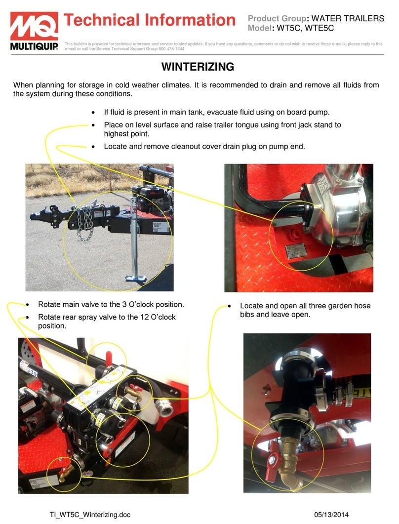
NOTICE
New hardware has been provided and is required for
installation of the new axle assemblies.
BRAKE
WIRES
INCORRECT
CORRECT
HANGER
MOUNTING
SHACKLE
TOP
TOP
3. Use new axle mounting screws (P/N 29248) and hex
axle nuts to secure new electric brake axle assembly.
4. Fasteners should be only be hand-tightened at this
time.
5. Use a ratchet and wrench to tighten axle mounting
screws (P/N 29248) and hex axle nuts (P/N 29249) as
shown in (Figure 12). DO NOT tighten screws all the
way. Leave a 1/16" gap as shown in Figure 13.
Figure 12. Tightening Axle Hex Nuts
Figure 13. Screw Gap
1/16”
GAP

WTE5C/WTE5HP SERIES WATER TRAILERS — SERVICE BULLETIN WT20180925 — 10/01/18 — PAGE 7
6. Using a hammer, gently tap (prevents damage to
screw head) the screws so that they lay flush against
the bracket (Figure 14A~D)
Figure 14. Tapping Axle Mounting Screws
A
B
D
C
Axle Wiring
CURB-SIDE
There are two wires extending from the axle tube as shown
in Figure 15, connect these wires as follows:
1. Using butt connectors (P/N 2540), attach the two wires
coming from the axle tube to the two wires coming
from the hub wire harness (Figure 15).
Figure 15. Curb-Side Wiring
STREET-SIDE
There are two wires extending from the axle tube as shown
in Figure 16, connect these wires as follows:
1. Using splice terminal connectors (P/N 19761), attach
the two wires coming from the axle tube to the two
wires coming from the hub wire harness (Figure 16).
Figure 16. Street-Side Wiring
NOTICE
Wire colors may be different than those shown in
Figure 15.
BUTT
CONNECTORS
AXLE
TUBE
HUB
WIRE
HARNESS
NOTICE
Wire colors may be different than those shown in
Figure 16.
BUTT
CONNECTORS
AXLE
TUBE
HUB
AXLE TUBE
HUB
WIRE
HARNESS
SPLICE
CONNECTORS

WTE5C/WTE5HP SERIES WATER TRAILERS — SERVICE BULLETIN WT20180925 — 10/01/18 — PAGE 8
HARNESS WIRING
1. Use splice terminals (P/N 19761) to attach one wire
to the RED wire and connect the other wire to the
WHITE wire.
2. Use cable-ties to secure the wire bundles to the wire
harness and axle tube as necessary.
Figure 17. Wire Harness Connections
A
B
C
WHITE WIRE
RED WIRE
WIRE HARNESS
WHEEL MOUNTING
Lug Nut Torque Requirements
It is extremely important to apply and maintain proper wheel
mounting torque on the trailer. Be sure to use only the
fasteners matched to the cone angle of the wheel. Proper
procedure for attachment of the wheels is as follows:
3. Start all wheel lug nuts by hand.
4. Torque all lug nuts in sequence. See Figure 18. DO
NOT torque the wheel lug nuts all the way down.
Tighten each lug nut in 3 separate passes as defined
by Table 2.
5. Check to see if the lug nuts are tight after the first 10, 25
and 50 miles of driving and before each tow thereafter.
Figure 18. Wheel Lug Nuts Tightening
Sequence
NOTICE
NEVER use an pneumatic air gun to tighten wheel
lug nuts.
Over-tightening lug nuts will result in breaking the studs
or permanently deforming the mounting stud holes in
the wheels.
WARNING
Lug nuts are prone to loosen after initial installation,
which can lead to death or serious injury. Check all
wheel lug nuts periodically.
1
2
3
4
5
5-LUG NUTS
LUG NUT
TORQUE WRENCH
STAR PATTERN
PNEUMATIC
AIRGUN
TORQUE
WRENCH
Table 2. Tire Torque Requirements
Wheel Size First Pass
FT-LBS
Second Pass
FT-LBS
Third Pass
FT-LBS
14" 20-25 50-60 90-120

WTE5C/WTE5HP SERIES WATER TRAILERS — SERVICE BULLETIN WT20180925 — 10/01/18 — PAGE 9
NOTICE
Affected axles (2,470 lbs.) must be returned to the
vendor as follows:
Ship to: Dexter MWR, 1845 South 300 West, Salt Lake
City, UT 841115
Attention: B. Quigley
Use account number: XPO Logistics 640849505
Affected axles must be shipped to vendor within 30
days.

Your Local Dealer is:
HERE’S HOW TO GET HELP
PLEASE HAVE THE MODEL AND SERIAL
NUMBER ON-HAND WHEN CALLING
© COPYRIGHT 2018, MULTIQUIP INC.
Multiquip Inc
,
the MQ logo are registered trademarks of Multiquip Inc. and may not be used, reproduced, or altered without written permission. All other trademarks are the property
of their respective owners and used with permission.
This manual
MUST accompany the equipment at all times. This manual is considered a permanent part of the equipment and should remain with the unit if resold.
The information and specifications included in this publication were in effect at the time of approval for printing. Illustrations, descriptions, references and technical data contained in
this manual are for guidance only and may not be considered as binding. Multiquip Inc. reserves the right to discontinue or change specifications, design or the information published
in this publication at any time without notice and without incurring any obligations.
UNITED STATES
Multiquip Corporate Office MQ Parts Department
18910 Wilmington Ave.
Carson, CA 90746
Contact: mq@multiquip.com
Tel. (800) 421-1244
Fax (310) 537-3927
(800) 427-1244
(310) 537-3700
Fax: (800) 672-7877
Service Department Warranty Department
(800) 421-1244
(310) 537-3700
(800) 421-1244
(310) 537-3700
Fax: (310) 943-2249
Technical Assistance
(800) 478-1244 Fax: (310) 943-2238
CANADA UNITED KINGDOM
Multiquip Multiquip (UK) Limited Head Office
4110 Industriel Boul.
Laval, Quebec, Canada H7L 6V3
Contact: infocanada@multiquip.com
Tel: (450) 625-2244
Tel: (877) 963-4411
Fax: (450) 625-8664
Unit 2, Northpoint Industrial Estate,
Globe Lane,
Dukinfield, Cheshire SK16 4UJ
Contact: sales@multiquip.co.uk
Tel: 0161 339 2223
Fax: 0161 339 3226
Service Bulletin
WTE5C/WTE5HP Series Water Trailers
This manual suits for next models
1
Table of contents
Other MULTIQUIP Utility Vehicle manuals

MULTIQUIP
MULTIQUIP WBH-21EF Guide

MULTIQUIP
MULTIQUIP WT5HPSG User manual

MULTIQUIP
MULTIQUIP WT5C User manual

MULTIQUIP
MULTIQUIP WT5HP User manual

MULTIQUIP
MULTIQUIP Whiteman series Guide

MULTIQUIP
MULTIQUIP WT5C Manual

MULTIQUIP
MULTIQUIP Whiteman series Guide

MULTIQUIP
MULTIQUIP Whiteman WBH-16EAWD Guide

MULTIQUIP
MULTIQUIP WTE5CSG User manual

MULTIQUIP
MULTIQUIP Whiteman WBH16 User manual