Star Cool SC-MCI40 Service manual

w
Operating and service manual
Star Cool refrigeration unit Model SC – MCI40 and SC – MCI40 – WC
Version 810900B
24-hour hotline support
Our service department is available 24 hours a day, 7 days a week -
providing easy access to the answers you need.
For further troubleshooting help, go to our website URL: m.starcool.com
or simply scan the QR code with Your smartphone
Bjerndrupvej 47,
6360 Tinglev, Denmark
Phone: +45 73 64 34 00
Fax.: +45 73 64 35 69
www.starcool.com
© Copyright Maersk Container Industry AS
Operating and service manual Version 810900B

1 of 222 pages
Operating and service manual
Preface
This version of the manual is edited by Maersk Container Industry AS.
All rights reserved.
This user’s manual is valid for software version 0240 or newer versions.
The information herein is subject to change without notice and does not represent a commitment
on any part of Maersk Container Industry AS.
While the information herein is assumed to be accurate, Maersk Container Industry AS assumes
no responsibility for any errors or omissions that may appear in this documentation.
This manual is valid for:
Model SC - MCI40 and SC - MCI40 - WC
Part number 810210A and 810200B.
Software version: 0240 - 02xx
Warnings
Do not operate or maintain this refrigeration unit until you have familiarized
yourself completely with the equipment and operating of this unit by reading the
instruction in this manual.
Do not perform any welding on the unit before disconnecting the power plug.
Disconnect main power supply to unit before inspecting the interior of the con-
troller box.
The unit is charged with R134a and ester oil BSE 55. Do not use any other refrig-
erant or oil.
Do not use contaminated refrigerant or oil.
Do not release R134a into the atmosphere. Use recovery equipment according to
present legislation.
During maintenance please observe that R134a is operating with high and low
temperatures in combination with high pressures, which may cause personal
injuries if not handled properly.
During recovery and maintenance of R134a unit personal protection equipment
has to be worn.
Do not trap any liquid refrigerant inside pipes during soldering work. This may
lead to explosion of pipe.

Operating and service manual
2 of 222 pages
Contents
Preface............................................................................................................................................................ 1
Warnings......................................................................................................................................................... 1
Legend ............................................................................................................................................................ 6
General description......................................................................................................................................... 8
Function description ....................................................................................................................................... 9
Start-up procedure..................................................................................................................................... 9
Climate Control Function ........................................................................................................................... 10
Temperature Control ................................................................................................................................ 10
Capacity Control and Limiter ..................................................................................................................... 10
Expansion Valve....................................................................................................................................... 11
Economizer Valve ..................................................................................................................................... 12
Dehumidication ...................................................................................................................................... 12
Condenser Fan......................................................................................................................................... 13
Evaporator Fan ........................................................................................................................................ 13
Defrost Function ...................................................................................................................................... 13
QUEST (optional)...................................................................................................................................... 15
Test s ...................................................................................................................................................... 15
Function test ........................................................................................................................................... 16
Full PTI ................................................................................................................................................... 16
Short PTI ................................................................................................................................................ 16
Data Log ................................................................................................................................................. 16
Alarm Action System (AAS) ....................................................................................................................... 18
Temperature control ................................................................................................................................. 18
Expansion valve control ............................................................................................................................ 18
Condenser fan control............................................................................................................................... 18
Dehumidication control ........................................................................................................................... 19
Defrost control......................................................................................................................................... 19
Electrical control ...................................................................................................................................... 19
Refrigeration system data............................................................................................................................. 20
Refrigerant charge, R134a......................................................................................................................... 20
General specication ................................................................................................................................ 20
Compressor – motor assembly................................................................................................................... 21
Frequency converter (FC).......................................................................................................................... 21
High Pressure cut – out switch................................................................................................................... 21
Fusible plug, receiver................................................................................................................................ 21
Economizer.............................................................................................................................................. 21
Evaporator coil......................................................................................................................................... 21
Condenser coil ......................................................................................................................................... 21
Evaporator fan ......................................................................................................................................... 22
Condenser fan ......................................................................................................................................... 22
Water cooled condenser (optional) ............................................................................................................. 22
Defrosting ............................................................................................................................................... 22
Fresh air exchange ................................................................................................................................... 23
Refrigeration controls ............................................................................................................................... 23
Electrical data.......................................................................................................................................... 23
Circuit Breaker......................................................................................................................................... 23
Contactors .............................................................................................................................................. 23
Fuses...................................................................................................................................................... 23
Power plug .............................................................................................................................................. 23
Power Cable ............................................................................................................................................ 24
USDA socket requirements ........................................................................................................................ 24
Evaporator fan motor................................................................................................................................ 24
Condenser fan motor ................................................................................................................................ 24

3 of 222 pages
Operating and service manual
Evaporator coil heaters ............................................................................................................................. 25
Temperature sensors, including USDA ........................................................................................................ 25
Pressure transmitters ............................................................................................................................... 25
Miscellaneous .......................................................................................................................................... 25
User Interface............................................................................................................................................... 26
Indicator lights......................................................................................................................................... 26
Display.................................................................................................................................................... 26
Key pad .................................................................................................................................................. 27
Menu overview.............................................................................................................................................. 28
General Page layout.................................................................................................................................. 29
Changing a parameter value ...................................................................................................................... 29
Activating a function................................................................................................................................. 29
Air exchange page.................................................................................................................................... 30
Operation...................................................................................................................................................... 31
Menu Structure ........................................................................................................................................ 31
General Operation.................................................................................................................................... 32
Temperature Setting................................................................................................................................. 32
Wake-up Mode ................................................................................................................................. 32
Contrast adjustment of the display ............................................................................................................. 32
PTI or Function Test execution ........................................................................................................... 33
Info Menu Viewing ................................................................................................................................... 36
Operation Parameter Setting ............................................................................................................. 40
Programs: ............................................................................................................................................... 41
Multiple Temperature Set points program, MTS............................................................................................ 41
Cold Treatment program, CT ..................................................................................................................... 42
Alarms ................................................................................................................................................... 43
Service Function Setting/Viewing ....................................................................................................... 44
Manual operations:................................................................................................................................... 45
Datalog view: .......................................................................................................................................... 46
Time adjust: ............................................................................................................................................ 46
Run time counters:................................................................................................................................... 47
Conguration:.......................................................................................................................................... 48
Serial Numbers ........................................................................................................................................ 49
°C and °F Temperature Scale Showing, Alternately ................................................................................ 49
Viewing graph of Supply and Return Temperature ................................................................................ 49
Manual Defrost Initiation ..................................................................................................................... 49
Water-cooling Activation/Deactivation ................................................................................................ 49
Emergency Operation ................................................................................................................................... 50
External interfaces ....................................................................................................................................... 51
General requirements ............................................................................................................................... 51
List of terms used for external interfaces .................................................................................................... 51
Functions overview................................................................................................................................... 52
Location of valves ......................................................................................................................................... 53
Location of motors, temperature sensors, humidity sensor and air exchange potentiometer ...................... 54
Location of pressure transmitters, high pressure switch and oil outlet port ................................................ 55
General trouble shooting .............................................................................................................................. 55
Trouble shooting for Star Cool main controller ............................................................................................. 56

Operating and service manual
4 of 222 pages
Detailed alarm description............................................................................................................................ 56
Alarm list ................................................................................................................................................ 57
Temperature Sensor Alarms (AL 1XX)......................................................................................................... 61
Pressure transmitter Alarms (AL 2XX) ....................................................................................................... 90
Other Sensor Alarms (AL 3XX) ................................................................................................................... 97
Power Alarms (AL 4XX) ........................................................................................................................... 104
Frequency Converter (FC) Alarms (AL 5XX) ............................................................................................... 116
Operation Alarms (AL 6XX)...................................................................................................................... 132
Alarms not used..................................................................................................................................... 144
Test Alarms (AL 8XX).............................................................................................................................. 145
Controller Alarms (AL 9XX)...................................................................................................................... 160
Calibration of air exchange sensor.............................................................................................................. 186
Replacing of unit ......................................................................................................................................... 187
Replacement Evaporator motor and fan...................................................................................................... 188
Replacement Condenser motor and fan ...................................................................................................... 189
Replacement of evaporator......................................................................................................................... 190
Old model ............................................................................................................................................. 190
New model ............................................................................................................................................ 191
Replacement of heating elements............................................................................................................... 192
Replacement of FC ...................................................................................................................................... 193
Replacement of compressor........................................................................................................................ 194
Replacement of compressor valve plate / cylinder head gasket ................................................................. 195
Service and maintenance ............................................................................................................................ 196
Evacuation of refrigerant......................................................................................................................... 196
Compressor pump down, operation .......................................................................................................... 197
Compressor pump down, replaced............................................................................................................ 197
Pump down of unit.................................................................................................................................. 198
Pressure Test......................................................................................................................................... 198
Charging of refrigerant ........................................................................................................................... 199
Charging of an empty unit....................................................................................................................... 199
Charging of unit low on charge................................................................................................................. 199
Leakage detection .................................................................................................................................. 200
Fan motors............................................................................................................................................ 200
Drying lter........................................................................................................................................... 201
Replacing of drying lter ......................................................................................................................... 201
Compressor........................................................................................................................................... 201
Check of oil level .................................................................................................................................... 201
Charging of oil ....................................................................................................................................... 202
Draining of oil from compressor ............................................................................................................... 202
Soldering .............................................................................................................................................. 203
Tables ......................................................................................................................................................... 203
Datalog description ................................................................................................................................ 203
Temperature Sensor [°C] - Resistance Table.............................................................................................. 207
Temperature Sensor [°F] - Resistance Table .............................................................................................. 208
Temperature [°C] - Pressure [BarE] Table - R134a ..................................................................................... 209
Temperature [°F] - Pressure [Psi] Table - R134a ........................................................................................ 210
Air exchange Sensor table Voltage - m3/h................................................................................................. 211
Relative Humidity Sensor table %RH - Voltage........................................................................................... 211

5 of 222 pages
Operating and service manual
Voltage – Pressure Table, Low pressure transmitter (AKS) .......................................................................... 212
Voltage – Pressure Table, Low pressure transmitter (NSK) .......................................................................... 213
Voltage – Pressure Table, High pressure transmitter (AKS) ......................................................................... 214
Voltage – Pressure Table, High pressure transmitter (NSK) ......................................................................... 215
Temperature Sensor - Voltage Table ......................................................................................................... 216
Tightening torques ................................................................................................................................. 217
P & I diagram .............................................................................................................................................. 218
Controller Unit Illustration ......................................................................................................................... 219
Star Cool Unit, installation dimensions ....................................................................................................... 220
Overall Wiring Schematic............................................................................................................................ 222
Operating and service manual
6 of 222 pages
Legend
Short name Name
AirEx Air Exchange
Alarm Alarm
AKS Danfoss pressure transmitter
Bat Battery
CalAex Calibration value AirEx
CalUs1 Calibration USDA sensor 1
CalUs2 Calibration USDA sensor 2
CalUs3 Calibration USDA sensor 3
CalCar Calibration Cargo sensor
CapAct Actual capacity
CapReq Requested capacity
Com Communication
ComQ Communication Quality FC
Cpr Compressor
CT Cold Treatment
FC Frequency Converter
Fcpr Compressor Frequency
FcprAct Compressor Frequency actual
FcprReq Compressor Frequency requested
Flower Compressor Frequency min.
Fpower Power supply Frequency converter
Fref Compressor Frequency requested
Fupper Compressor Frequency max.
Gear Gear
Gnd Ground
Hevap Evaporator Heater
I1 Current Phase 1
I2 Current Phase 2
I3 Current Phase 3
Idc Current in DC Frequency Converter
Ifc Current in AC Compressor Motor
IceMas Theoretical Ice mass in Evaporator
LED Light Emitting Diode
MaxInt Max. internal temp. controller
Mcpr Compressor Motor
McOH Condenser Motor Over Heat
Mcond Condenser Motor
Mevap Evaporator Motor
Mevap1 Evaporator Motor 1
Mevap2 Evaporator Motor 2
Mevap1OH Evaporator Motor 1 overheat
Mevap2OH Evaporator Motor 2 overheat
MTS Multi Temperature Settings
NSK SAGInoMIYA pressure transmitter
OprMod Operation Mode
PCB Printed Circuit Board
Pdis Discharge Pressure
Short name Name
Pfc Power used by Frequency Converter
PhDir Phase Direction
Psuc Suction Pressure
Ptot Power Total
PTI Pre Trip Inspection
PTI Short Pre Trip Inspection Short
Pwr Power
RH Relative Humidity
RHset Humidity Set point
RMM Remote Monitoring Modem
(power line communication)
SHTV Superheat Thermo Valve
Shp High pressure switch
SHReq Superheat Requested
T0 Calculated Evaporator
Temperature
Tact Actual Temperature
Tamb Ambient Temperature
TC Calculated condenser
Temperature
Tcargo Cargo Temperature
Tdis Discharge Temperature
Tevap Evaporator Temperature
Tfc Frequency converter Temperature
Tint Tinternal (controller board)
Tret Return Air Temperature
Tset Temperature Setpoint
Tsuc Suction Temperature
Tsup Supply Air Temperature
Tsup1 Supply Air Temperature 1
Tsup2 Supply Air Temperature 2
Tusda1 USDA 1 Temperature
Tusda2 USDA 2 Temperature
Tusda3 USDA 3 Temperature
U12 Voltage Phase 1-2
U13 Voltage Phase 1-3
U23 Voltage Phase 2-3
U/f Voltage/frequency ratio
Ubat Battery voltage
Udc DC voltage in Frequency Converter
Umean Mean Voltage = L1+L2+L3/3
Umotor Mean Voltage Compressor Motor
Veco Economizer Valve
Vexp Expansion Valve
Vhg Hot gas Valve
Warn Warning
7 of 222 pages
Operating and service manual
Prex Description
FFrequency
HHeater
I Current
MMotor
PPressure
QPower
RH Relative humidity
S Switch / contact / key
SH Super heat
TTemperature
T0 Saturated suction tem-
perature
UVoltage
VValve
Contraction Full name
Amb Ambient
Bat Battery
Cond Condenser
Cpr Compressor
Dis Discharge
Eco Economizer
Evap Evaporator
Fc Frequency converter
Motor Compressor motor
Pwr Power
Ret Return
Suc Suction
Sup Supply
Sufx Specication
Act Actual
In Input
OH Overheat
Out Output
Req Requested
Set Setpoint

Operating and service manual
8 of 222 pages
General description
The units, models SCU-40 and SCI-40 are electric powered picture frames, cooling and
heating units operating on refrigerant R134a.
The unit is designed to maintain cargo temperatures in a range from –30°C (-22°F) to +30°C (86°F).
The unit is designed to operate in ambient temperatures from –30°C (-22°F) to +50°C (122°F).
The outer front frame is constructed of marine grade aluminium, 5000 and 6000 series, designed to
serve adequately as the container end wall.
The rear bulkhead is made of food-approved material.
The unit is designed to operate with satisfaction under sea going and environmental conditions as
specied below:
• Salt – laden air, sea spray and high humidity.
• Rolling: Amplitude of 30° each side, period of 13 seconds.
• Pitching: Amplitude of 6° each side, period of 8 seconds.
• Permanent list: 15° on each side.
• Shock: 2g horizontal and 5g vertical.
• Vibrations: Of the types encountered on ships, trucks and rail.
The unit consists of the following modules.
• Frame module
• Condenser / compressor module
• Evaporator module
• Evaporator fan module
The cooling system of the unit is equipped with a two – stage compressor, electrically driven through
a FC.
The cooling system is also equipped with an economizer, which performs the task of sub-cooling the
liquid from receiver to evaporator, thereby increasing the cooling capacity of the cooling unit.
The evaporator and economizer are controlled by electronic expansion valves.
The equipment is designed to operate on a nominal 410/450 V AC, 3 phase, 50/60 Hz, primary power
source, according to ISO 1496-2.
An integrated dual winding transformer supplies the control circuit voltage. One winding for 24 V AC
(for RMM modem supply) and another for 26 V AC converted to DC-Voltage in the controller (for
controller and contactor supply). The output voltage is dependent on supply voltage.
An automatic system, power supply sensing and correction, is provided to ensure the correct
direction of rotation for the fan motors. This is done regardless of the incoming phase sequence
from the primary power supply, provided that all fan motors are wired correctly.
An optional water-cooled condenser is mounted in series with the air-cooled condenser. This
water-cooled condenser allows operation of unit below deck, where no air ventilation is possible,
provided that water connections are present.
The unit is controlled by an electronic controller manufactured by Lodam Electronics, controlling the
supply temperature probe in chilled mode (temperature setting above or equal to –5°C (23°F)) and
the return temperature in the frozen mode (temperature setting below –5°C (23°F)).
Controller accuracy is ±0.25°C (±0.45°F).
The unit can operate the evaporator fans in low speed and high speed. From the controller display,
Normal or Economy mode can be selected under operation menu.
In economy mode the fans always run on low speed. In normal mode the fan speed can run in high
or low speed depending on running conditions.
The air from the unit is delivered to the bottom of the container, with return air through the top of
the evaporator coil section (bottom air delivery).
The unit is equipped with a de-humidication function controlled by the electronic controller of the
unit. The humidity setpoint can be set in the range from 95 – 65% (or 50 % with closed ventilation)
RH. The unit can control to the lowest level. The de-humidication function is active as long as the

9 of 222 pages
Operating and service manual
temperature control is in set point range. The unit is equipped with heating elements, mounted
under the evaporator coil, for the de-humidication.
The de-humidication system is also active in economy mode.
The unit is equipped with a dual system for defrosting. There is installed a hot gas valve, in the
refrigeration system, for hot gas defrosting of the evaporator coil. Furthermore the heating ele-
ments, mounted under the evaporator coil, are energized during defrost.
This dual system for defrosting ensures a fast defrost sequence and thereby only a very small
input of heat to the container. This results in very small temperature variations for the transported
cargo, after a defrost sequence.
The dual system for defrost also ensures an even distribution of heat to the evaporator coil. The
result of this is that there is no building up of ice in corners or other places of the evaporator coil.
The two defrost systems, hot gas and heating elements, are independent. This ensures a defrost
sequence to be carried out, even with one system failing.
A demand defrost system is integrated in the software ensuring that the evaporator coil will not ice
up.
The unit is equipped with a datalogger incorporated in the controller.
The logging interval is in predened intervals, 15, 30, 60, 120 or 240 minutes.
The logging of the USDA – sensors (3 pieces) and Cargo - sensor is done with an interval of one
hour according to USDA requirements. With a logging interval of one hour, there is storage capacity
for 365 days of temperature loggings.
Datalogger accuracy is ±0.25°C (±0.45°F).
The data – log can be retrieved with a PC – system Starview and Psion Logman, via high-speed
serial communication port.
The controller has a battery back (not rechargeable) – up system for the datalogger, which after
power switch off of the unit continues logging in battery mode 120 times and then stops.
The controller is prepared for communication with Remote Monitoring Modem (RMM), according to
ISO standard 10368, for monitoring at the ship bridge or control room.
Events + Alarms and Short Log can be retrieved by Refcon, Logman, StarView and can be viewed by
Refcon, LogView and StarView.
Extended Log can only be retrieved by Logman and StarView and shown in LogView and StarView.
Function description
Start-up procedure
The start-up procedure ensures that the system is started safely after the following events:
• Unit has been out of use
• Main failures
• Defrosting
• PTI test
• Service mode
• Alarm mode
The start-up procedure has 5 modes:
1. Initialize: Self check controller.
2. Stabilize: The evaporator fan operates at high speed to ensure that temperature sensors are at
current temperature.
3. Crank case heating: If Tamb is lower than 2°C (36°F) heat is applied until Tfc is above 12°C
(54°F).
4. Ramp up
5. Terminate: Switching to normal temperature and valve regulation.

Operating and service manual
10 of 222 pages
Climate Control Function
Temperature Control
This function incorporates the container temperature controller.
The function has 2 modes: Chill and Frozen.
• Chill
If Tset more than (>) -5°C (23°F) the chill mode is activated and Tact = Tsup.
• Frozen
If Tset is less than or equal to (≤) -5°C (23°F) the frozen mode is activated and Tact = Tret.
The value the Tset limit is dependent on software version.
This function has four modes: Pull down, Pull up, Cool, and Heat.
Pull Down / Pull Up mode:
In Pull Up and Pull Down mode no in-range alarm is given.
Upon start-up, defrost or another mode deactivating temperature control (e.g. manual, set-point
alternation, PTI) the temperature control is set to Pull Down or Pull Up mode depending on Tact
being above or below Tset.
As long as temperature is not within Tset +/- ranges, the function remains in CoolPullDown or
HeatPullUp mode. If temperature is within range, the green “IN-RANGE” indicator light starts
ashing. When the temperature has been within Tset +/- ranges for 30 min. the green “IN-RANGE”
indicator light is constant on.
Cool / Heat mode:
Temperature is within Tset +/- ranges and the green “IN-RANGE” indicator light is constant on.
If temperature is in out-of-range condition for more than 2 hours, the IN-RANGE indicator lights
start ashing. After 4 hours out-of-range condition, an in-range alarm is set.
On the basis of Tact and Tset the function calculates the requested capacity (CapReq) value by
means of a PID controller. CapReq is the desired chilling / heating capacity. CapReq value can
range from –100% to +100%. –100% being maximum cooling and +100% being maximum heat-
ing.
Capacity Control and Limiter
On the basis of requested capacity this function determines operation mode and actions of the in-
dividual system components (compressor, valves, heating elements) and ensures that compressor
minimum off time is observed.
This function has 5 gears (modes). On the basis of requested capacity, the gear is determined.
Compressor frequency is directly dependent upon current mode. Evaporator heater, on the other
hand, is gear independent.
There is overlap over the modes to maintain slow mode shifting.
Gear Function
Off Everything is turned off.
Start up If cooling is required, the FC is starting at default frequency before shifting to
correct cooling mode.
PWM On/Off regulation of compressor.
CoolEco Maximum cooling capacity with use of economizer.
Heat Only the heaters are used.
Defrost Heaters are always used and hot gas valve is used if ambient temperature is
above 5˚C (41˚F).
The capacity of the unit is controlled between maximum cooling capacity (-100% capacity) and
maximum heating capacity (+100% capacity). This is done by regulation of the compressor speed
by means of the FC or on/off regulation. In maximum capacity (+100% capacity) the unit uses the
heating elements, by means of pulse width modulation, to control the capacity.
11 of 222 pages
Operating and service manual
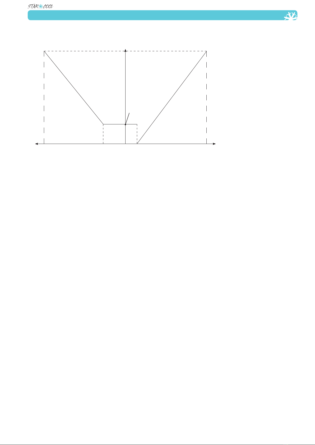
Below gure indicates the ranges for the capacity and compressor speed (frequency).
20 Hz (600 rpm)
line 2
line 3line 1
Set point Set point
110 Hz (3300 rpm)
-100%
cooling
100%
heating
-20% +10%
Compressor frequency, Hz
Capacity
Line 1: The area where cooling is requested, controlled by the frequency converter.
Line 2: The area where the compressor is on/off regulated.
Line 3: The area where heating is requested, controlled by pulsing of heating elements.
The limiter function secures that the controller operates with valid settings to protect the unit in
order to maintain the conditions for the cargo. To maintain the set point temperature, capacity
control constantly monitors and adjusts the capacity. The limiter acts as a brake to the capacity
change requests from capacity control and thereby controlling how fast the capacity can change,
so that safe operation of the unit constantly is ensured.
The limiter monitors the following parameters from the unit and generates a limiter factor for each:
• IFC, to limit the maximum current draw from the FC.
• TFC, to limit the maximum internal FC temperature.
• Tc, to limit the maximum condenser pressure (and temperature).
• T0, to ensure a minimum evaporator pressure.
• Teco, to ensure a minimum middle pressure in the compressor.
The largest of the factors is used as the active limiter. If the limiter factor is higher than the re-
quested capacity change, the capacity is actually reduced instead of increased.
If for example the ambient temperature is very high, the requested capacity may increase the FC
temperature over its limits and so the limiter will reduce the capacity until a safe and stable opera-
tion condition for the FC has been reached.
Expansion Valve
This function ensures optimum evaporator superheat (SH) and calculates the percentage of open-
ing (SHVod) and controls the valve. This function is active during compressor operation. Valve is
closed during compressor turn off.
Expansion valve function includes the following sub-functions:
• MSS (Minimum Stable Superheat search).
• Superheat control.
• MOP (Maximum Operating Pressure).
MSS
This function searches for minimum stable superheat within the ranges SHmin and SHmax. With a
stable T0, SHset is reduced and with an unstable T0, SHset is raised.
SHact: = Tsuc – T0
Superheating
Function output is the expansion valve opening rate (Vexp).

Operating and service manual
12 of 222 pages
At start-up the opening rate is 0%.
The electronic expansion valve is an on/off valve controlled on the basis of opening rate with a
constant cycle time.
MOP function
The MOP function prevents the suction pressure from getting too high.
Economizer Valve
This function ensures optimum sub cooling of liquid to the evaporator and cooling of the FC.
In addition, the cooling capacity is increased, COP is enhanced and compressed gas temperature is
reduced.
Function output is the economizer valve opening rate (Veco).
The economizer control has two modes:
• Superheat control
• FC cooler.
Superheat control
Valve opening rate control is based on calculations.
FC cooler
This function is active during compressor operation.
Dehumidication
The dehumidication function dehumidies air in the container by means of a heater.
This function is can only be activated if the temperature control function is active.
Dehumidication is achieved by decreasing evaporator surface temperature.
This is done through activation of the heater and letting the temperature control increase cooling
capacity resulting in an evaporator temperature descending.
This function has 3 modes:
Off
Active
Override
Dehumidication: Off
The dehumidication function is in the OFF position.
Dehumidication: Active
The heater (Hevap) is activated when RH is more than (>) RHSet and deactivated when RH is less
than (<) RHSet – 3%
The humidity set point can be set in the range 50% to 95% relative humidity. The range 50% to
64% is only possible with no fresh air - evap. ventilation in low speed. The range 65% - 95% is
possible to run with fresh air - evap. ventilation in high speed.
Dehumidication: Override
Accessing override mode if:
- Cooling demand exceeds 80% capacity.
- Large demand for heating.
- PTI
- A fatal alarm is active.
- When operating without FC.
- Manual operation is active.
- Defrosting
Other comments
The dehumidication icon is shown in the display even if override is active.
The heat icon follows the current state of the heater.

13 of 222 pages
Operating and service manual
Condenser Fan
Condenser fan control will reduce condenser pressure through condenser ventilation.
The condenser pressure control also monitors the compressor outlet pressure in case of water-
cooling.
This function is activated when control is being in the automatic mode.
Condenser pressure control has two primary modes:
Air-cooled
Water-cooled
Air-cooled
In the air-cooled mode ventilation takes place in the following way:
Depending on the compressor outlet pressure, the fan is Off or runs in 2 different speeds:
High and Low.
The fan runs in 4 modes: Off, low-speed, high-speed and a cycle shifting between high and low-
speed in two minutes intervals.
If Tamb is more than (>) 48°C (118°F) or the compressor outlet pressure remains constantly high,
the condenser fan constantly runs at high speed.
Water-cooled
If the condenser fan is constantly on for more than 1 hour, an alarm will be given.
The fan runs in 4 modes: Off, low-speed, high-speed and a cycles shifting between high and low-
speed in two minutes intervals.
Evaporator Fan
The evaporator fan function ensures correct fan speed (high or low).
The function is active in the automatic mode.
This function has 2 modes:
Normal
Economy
Normal
Low speed in the frozen mode or if the following three conditions are set
• Tset is more than or equal to (>) 0°C (32°F)
• No fresh air exchange
• Dehumidication is turned off
Otherwise high speed
Economy
The fans run at a constant low speed.
Economy mode is switched on by the operator.
Defrost Function
Defrost function ensures regular evaporator defrosting. The function is active in automatic mode.
The defrost function has 4 modes:
Wait
Initialize
Execute
Terminate
Wait
In the wait mode the time is refreshed for the next defrost provided that the following conditions are
satised:
• Compressor is running
• T0 is less than (<) T0min.

Operating and service manual
14 of 222 pages
Wait mode termination can be due to:
• Calculated ice amount in the evaporator is above critical level (Demand defrost)
• Defrosting action initiated manually (Manual defrost initiation)
Initialize
Wait until condenser temperature is above 50°C (122°F), however no more than 300 sec.
Execute
In this mode the actual evaporator defrosting takes place:
A Defrost start event is made in the trip log.
Cooling system termination results in compressor initiation, only ramp up mode is executed.
Evaporator fan is stopped.
Evaporator heating elements are turned on.
Compressor runs at a constant frequency at 83% of full speed.
Expansion valve control is deactivated.
Hot gas valve is used to heat the evaporator from the inside with the hot gas from the compres-
sor.
Evaporator defrosting terminates when evaporator temperature, Tevap, is above defrost termina-
tion temperature for 2 min. or upon elapse of max. defrost time.
A defrost stop event is made in the data log with the current interval and Tevap temperature.
Terminate
Terminate mode is dividable into two parts:
• Evaporator re freezing preventing remaining water drops on evaporator from blowing into con-
tainer upon evaporator fan initiation.
• Termination ensuring low evaporator fan speed to prevent shock boiling and to ensure that the
temperature controller takes over in a controlled way.
After termination, the unit continues normal operation again with the same setpoint temperature as
before defrost start.
General information
If the Tevap sensor is not OK, adaptive defrosting uses a reduced defrost interval compared to
normal calculated defrost intervals.
Set-point alteration leads to a new calculated defrost interval, and defrost starts when the defrost
criteria is reached.
With manual defrost initiation the current defrost interval is set to default defrost interval.
Manual defrost termination
Upon manual defrost termination, termination state is entered. No adaptive adjustment takes
place when defrosting is manually initiated.
Regarding user interface
Defrost icon is displayed during defrost function execution.
Other comments
If service mode or PTI mode is selected during a defrost, the defrost mode is terminated and the
time for the next defrosting is set to the preset value as if a normal defrost end had occurred.
If the unit is shut off for some reason during a defrost and the power disappears for less than (<)
12 hours, the unit will start and try to nish the defrost again when the power returns.
If the unit is shut off for more than 12 hours, the active defrost is terminated and the defrost
function enters the wait state.

15 of 222 pages
Operating and service manual
QUEST (optional)
QUEST is a program based on a xed protocol designed to reduce the energy consumption of the
unit, when operating in the interval -1°C to +30°C (30°F to 86°F). This energy saving is mainly
obtained by regulating the compressors on/off time and the evaporator fan speed.
Please note that when Tsup is in the range -1°C to +15°C (30°F to 59°F) its value can vary -2°C -
+1°C (28 °F to 34°F) from setpoint.
Please note that when Tsup is in the range +15°C to +30°C (30°F to 86°F) its value can vary -4°C
- +1°C (25°F to 34°F) from setpoint.
QUEST is, as default, set to either AUTO or OFF depending on customer requirements.
To deactivate QUEST:
1. Press
2. Use or to select O03 QUEST and press
3. Select “OFF” by using or and press
To activate QUEST:
1. Press
2. Use or to select O03 QUEST and press
3. Select “AUTO” by using or and press
If O03 is empty, QUEST is not installed.
Star Cool is responsible for that the QUEST function is operating within the parameters and the
running pattern dened by the protocol. Star Cool is however not liable for any consequent dam-
ages caused by the QUEST functionality.
Tests
The unit has 2 (3) test functions:
• Function test.
• PTI (Pre-Trip Inspection) test.
• PTI short (optional)
The PTI test is a function test followed by a capacity test where the requested temperature must
be reached within the time limit.
At test initiation an event is generated in the log.
During function and PTI test the normal alarm system remains active. If an alarm is triggered dur-
ing test operation, it appears in the display and will be written in the log as it is the case during
normal operation.
In case of a fatal alarm during testing the test is terminated and the unit remains off.
Function or PTI sub-test failure causes an alarm ”PTI FAILURE” to be generated.
In case of Function or PTI sub-test pass an event, ”Test status” is displayed.
For more information, please see event list.
Clear the alarm list before starting a test. If there should be any active alarms in the alarm list
when a function or a PTI test is started, the test will always fail even if all the individual test steps
PASS without failures.
PTI menu has a primary status and a status for each sub-test with own indexes.
Only the primary status for a PTI test is memorized when supply voltage is removed.
When PTI is initiated a Trip start is set in the data log.

Operating and service manual
16 of 222 pages
Function test
Function test is a unit component test. (Non destructive)
Test is based on a GO/NO GO procedure. All tests must be executed without failure one by one for
the function test result to be PASS.
Note: The tests can also be performed individually.
Function test includes the following items:
1. PTI – init
2. Controller test
3. Power check
4. Evaporator fan (Mevap)
5. Condenser fan (Mcond)
6. Heating element (Hevap and Htray)
7. Probe check (not implemented in ver. 240)
8. Compressor/FC/valve test (Vexpansion, Vhotgas and Veconomizer)
9. Test completion / status
NOTE: At ambient temperature above 40°C (104°F) and below –20°C (-4°F) the unit has
to be running in normal operating mode at setpoint of 0°C (32°F) for of 10 minutes with
compressor running before executing a function test or PTI test.
The reason for this is to ensure correct function of unit during PTI test or function test.
PTI Test:
The purpose of the PTI test is to verify the presence of cooling performance.
The test is based on a GO/NO GO procedure. All tests must be executed without failure one by one
for the PTI test results to be PASS.
PTI test includes the following test items:
Full PTI
1. Function test
2. 5°C (41°F) test
3. 0°C (32°F) test
4. -18°C (-0.4°F) test
5. Defrosting
6. Test completion / status
Short PTI
Short PTI includes the following test items:
1. Function test
2. 5°C (41°F) test
3. 0°C (32°F) test
4. Defrosting
5. Test completion / status
Data Log
The controller has a data log to record operation of the unit. The data log includes 4 items:
• Data.
• Extended data.
• Alarms.
• Event data.
The logged data in the data log can be seen:
• On the display menu L01, the viewable temperatures are listed.
• On the display menu L03, the logged temperatures can be viewed graphically.
• Retrieved via the program RefCon and the RMM modem and the power line.
• Retrieved via a program, LogMan, on a PSION pda using the retriever socket.
• Retrieved via the StarView program using the retriever socket.

17 of 222 pages
Operating and service manual
When an alarm is activated it triggers a complete log, however max. one per 15 min.
The datalogger can hold approximately 10.000 logs or more than 1 year of loggings with default
logging interval of one log per hour.
The following tables show retrievables with Starview and Psion Logman software:
File Download Info
F1 Signature
Header
F2 Container ID
F3 Controller ID
F4 Controller Software
F5 Retriever Software
F6 Extraction date
F7 Comments
Data log
D1 DT Date
Stamp
D2 Time
D3 Log Type [Event, Data, Log]
D4 Event ID
Events + Alarms
D5 Param. 1
D6 Param. 2
D7 Param. 3
D8 Param. 4
D9 Param. 5
D10 Tsup Supply Air Temperature [°C]
Short Log
D11 Tret Return Air Temperature [°C]
D12 Tusda1 USDA 1 Temperature [°C]
D13 Tusda2 USDA 2 Temperature [°C]
D14 Tusda3 USDA 3 Temperature [°C]
D15 Tcargo Cargo Temperature [°C]
D16 Tset Temperature Set Point [°C]
D17 Humidity Relative Humidity [%]
D18 AirEx Air Exchange [m3/h]
D19 Psuc Suction Pressure [BarE]
Extended Log Type 1
D20 Pdis Discharge Pressure [BarE]
D21 Fpower Net frequency [Hz]
D22 Upower Highest power voltage of U1, U2, U3
D23 I1 Current, Ph. 1 [A]
D24 I2 Current, Ph. 2 [A]
D25 I3 Current, Ph. 3 [A]
D26 Ifc FC current [A]
D27 Fcpr Compressor Frequency [Hz]
D28 Heater Heating element [%]
D29 Mevap Evaporator motor status
D30 Mcond Condenser motor status
D31 Tfc Frequency module Temperature [°C]
D32 Tamb Ambient Temperature [°C]
Operating and service manual
18 of 222 pages
D33
Extended Log Type 2
Extended Log Type 2
D34
D35
D36
D37
D38
D39
D40
D41
D42
D43
Header can be retrieved by Refcon, Logman, StarView and can be viewed in Refcon, LogView and
StarView.
Extended Log Type 1 can only be retrieved by Logman and StarView and shown in LogView and
StarView.
Extended Log Type 2 can only be retrieved by StarView and viewed in StarView.
StarView is the unique program designed for communication with a Star cool unit through a serial
connection to a PC.
Alarm Action System (AAS)
This function denes what to do if a sensor is defect. The strategy is to substitute the missing
sensors reading with the value from another sensor + a constant so that the unit can maintain its
functionality with reduced precision.
Temperature control
Chill mode
Defect sensor(s) Substitution sensor / Action Alarm
Tsup1 (2) Tact = Tsup2 (1)
Tsup1 and Tsup2 Tact = Tret + constant 611, Too many sensor err
Tsup1, Tsup2 and Tret Tact = Tevap + constant
Tsup1, Tsup2, Tret and Tevap ** 600, No control sensor
Freeze mode
Defective sensor(s) Substitution sensor / Action Alarm
Tret Tact = Tevap + constant
Tret and Tevap Tact = Tsup1 + constant 611, Too many sensor err
Tret, Tevap and Tsup1 Tact = Tsup2 + constant
Tret, Tevap, Tsup1 and Tsup2 ** 600, No control sensor
** = No more available sensors for substitution.
Expansion valve control
Defective sensor(s) Substitution sensor / Action Alarm
Psuc Emergency injection 611, Too many sensor err
Tsuc Emergency injection 611, Too many sensor err
Condenser fan control
Defective sensor(s) Substitution sensor / Action Alarm
19 of 222 pages
Operating and service manual
Pdis Start up:
Condenser fan speed = slow
Chill/Freeze mode: Condenser
fan speed depends on ambient
temperature.
Tamb Tamb = Tinternal
Tret, Tevap and Tsup1 Tact = Tsup2 + constant
Tamb and Tinternal Tcmin
Dehumidication control
If dehumidication is active:
Defective sensor(s) Substitution sensor / Action Alarm
RH Stop dehumidication 614, Humidity deactivated
Defrost control
Defective sensor(s) Substitution sensor / Action Alarm
Tevap Tsuc
Tc Tc = constant
Psuc(T0) T0 = Tevap
Psuc (T0) and Tevap Only electrical defrosting.
T0 = constant
Tsuc Only electrical defrosting
T0 = constant
Tamb Tinternal + constant
Tamb and Tinternal Always electrical defrosting
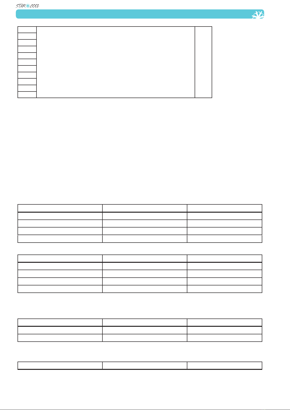
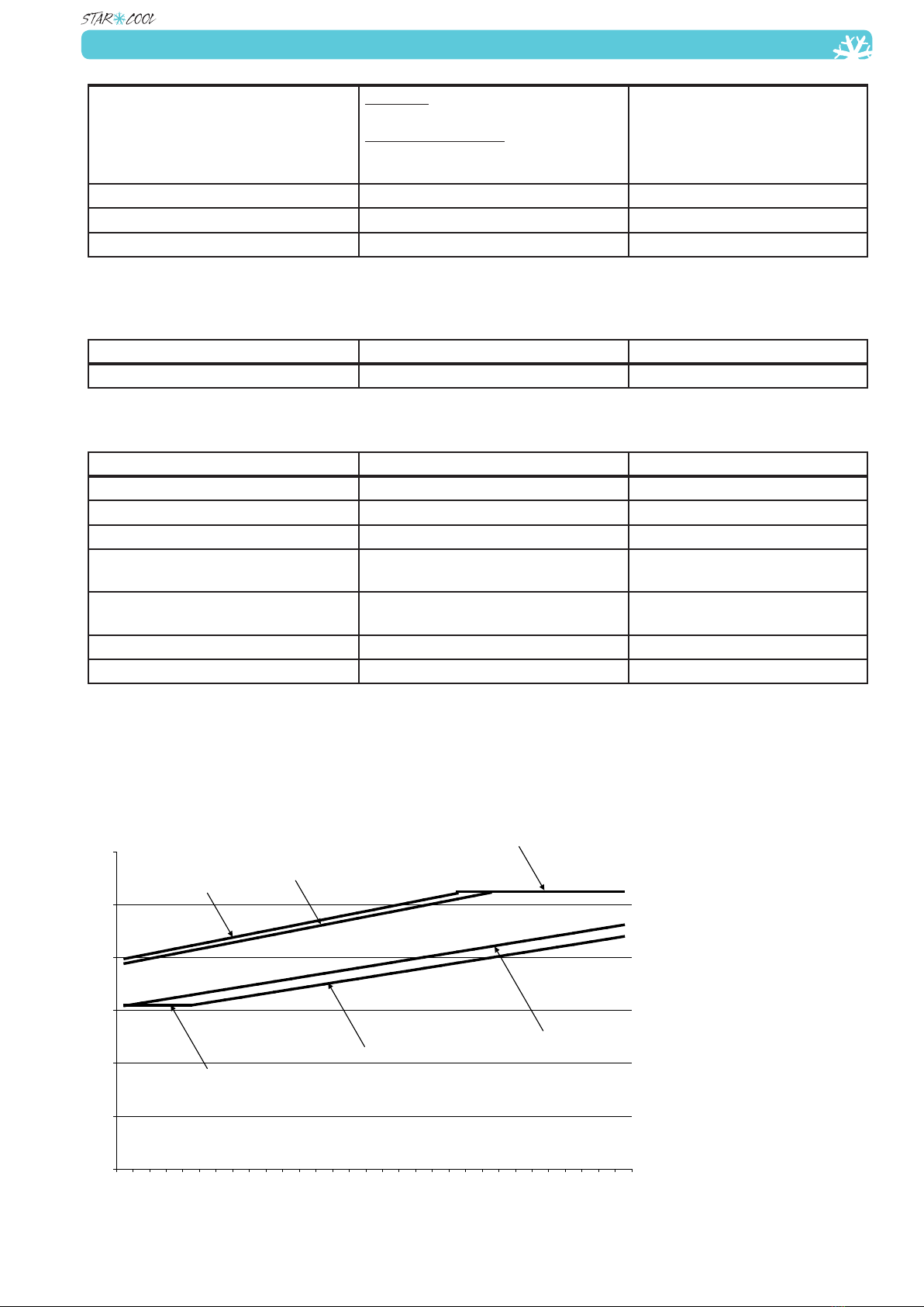
Electrical control
Following graphical illustration shows the accepted volt/Hz range and the set off values for the
alarms AL 414 (Fatal Alarm), AL 415 (Fatal Alarm), AL 416 (Fatal Alarm), AL 417, AL 418, AL
419, AL 427, AL 428 and AL 429 (Fatal Alarm), based on the table below.
0
100
200
300
400
500
600
40 41 42 43 44 45 46 47 48 49 50 51 52 53 54 55 56 57 58 59 60 61 62 63 64 65 66 67 68 69 70
Hz
Volt
min. U/f - AL429
min. voltage - AL417, AL418, AL419
alarm U/f - AL427
max. U/f - AL429
alarm U/f - AL428
max. voltage - AL414, AL415, AL416
This manual suits for next models
3
Table of contents
Popular Portable Generator manuals by other brands

BNC
BNC 725 user guide

Excel Power
Excel Power XL1400i owner's manual

Generac Portable Products
Generac Portable Products 9719-3 owner's manual

FRONIUS
FRONIUS TransPocket 150 operating instructions

Generac Power Systems
Generac Power Systems GP3000i owner's manual

SIGNALCORE
SIGNALCORE SC5507A Hardware manual


