YSONIC YS4000i User manual

WARNING: SAVE THIS MANUAL FOR FUTURE REFERENCE
INVERTER GENERATOR
USER'S MANUAL
YSONIC GENERATOR
YS4000i
This manual contains important information regarding safety. Operation,
maintenance and storage of this product. Before use, read carefully and
understand all cautions, warnings, instructions and product labels. Failure to
do so could result in serious personal injury and/or property damage.
Portable Inverter Generator
3000 Running Watts | 3300 Peak Watts

1
UNPACKING
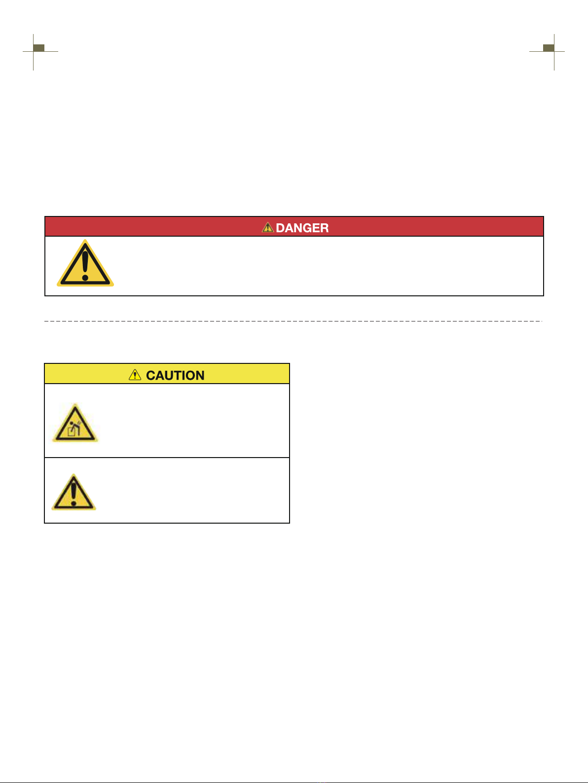
Always have assistance when lifting
the generator. The generator is heavy;
lifting it could cause bodily harm.
Avoid cutting on or near staples to
prevent personal injury.
Tools required - box cutter or similar device.
1. Carefully cut the packing tape on top of the carton.
2. Remove socket wrench, and oil funnel and save for
later.
3. Carefully cut two sides of the carton to remove the
generator.
WHAT COMES IN THE BOX
Spark Plug Socket Wrench (1)
Dual-Purpose Screwdriver (1)
User Manual (1)
Funnel (1)
DISCLAIMERS:
All information, illustrations and specifications in this manual are based on the latest information available at the
time of publishing. The illustrations used in this manual are intended as representative reference views only.
Moreover, because of our continuous product improvement policy, we may modify information, illustrations and/or
specifications to explain and/or exemplify a product, service or maintenance improvement. We reserve the right to
make any change at any time without notice. Some images may vary depending upon which model is shown.
ALL RIGHTS RESERVED:
No part of this publication may be reproduced or used in any form by any means - graphic, electronic or
mechanical, including photocopying, recording, taping or information storage and retrieval systems - without the
written permission of CHONGQING DINKING POWER MACHINERY CO., LTD
This manual contains important instructions for operating this inverter generator. For your
safety and the safety of others, be sure to read this manual thoroughly before operating the
generator. Failure to properly follow all instructions and precautions can cause you and others
to be seriously hurt or killed.

2
TABLE OF CONTENTS
SAFETY WARNING 3
SAFETY INSTRUCTIONS 4
NAMES OF COMPONENTS 6
CONTROL FUNCTIONS 7
PREPARATIONS 9
1.Fuel............................................................................................................................................9
2.Oil................................................................................................................................................9
3.Pre-operation inspection............................................................................................................10
STARTING UP THE GENERATOR 11
SHUTTING DOWN THE GENERATOR 12
USING THE GENERATOR 13
1.Service environment of the generator.......................................................................................13
2.Generator wiring........................................................................................................................13
3.Generator grounding.................................................................................................................14
SERVICE AND MAINTENANCE 15
1.Spark plug inspection...............................................................................................................16
2.Adjustment of the carburetor.....................................................................................................17
3.Replacement of oil....................................................................................................................17
4.Air filter......................................................................................................................................18
5.Fuel filter screen........................................................................................................................19
STORAGE AND TRANSPORT 20
1.Generator storage.....................................................................................................................20
2.Generator transport...................................................................................................................21
TROUBLESHOOTING 22
TECHNICAL PARAMETERS 23
CIRCUIT DIAGRAM 24
CHOOSING A GENERATOR 26

3
SAFETY WARNING
Personal and property safeties of you and others are very vital. Please read the Safety
Warning in the User's Manual and the decals of the generator set carefully.The Safety
Warning can alert you to those potential hazards that could harm you and others. In front
of each Safety Warning, there is one of four words "DANGER" "WARNING",
"ATTENTION", and "CAREFUL". Details are as follows:
Failure to follow the instruction will result in
being in peril of your life or extremely serious
injury.
Failure to follow the instruction will result in
being in peril of your life or very serious injury.
Failure to follow the instruction will result in
minor injury.
Failure to follow the instruction will result in the
damage to your generator set and other properties.
For portable generators where the neutral is floating, the operator's manual shall include the following wording
or equivalent:
The portable generator stator winding is isolated from the frame and from the AC receptacle ground pin; and
Electrical devices that require a connection between one conductor pin and the grounded receptacle pin may not
function properly.
NEUTRAL FLOATING

4
SAFETY INSTRUCTIONS
Before operating the generator, it will help you avoid accidents to read and understand the Manual
and familiarize yourself with the safe operation procedures of the generator.
Please do not use indoors Please do not use in humid
environment
Please do not connect it to
household appliances directly Please do not smoke when refueling
Please do not spill when refueling
Please shut down the generator
before refueling

5
SAFETY INSTRUCTIONS
SAFETY LABELS AND DECALS

6
NAMES OF COMPONENTS
Lifting handle
Fuel tank cap
Control panel
Startup handle
Left enclosure
Spark plug cover
plate
Muffler
Remove right
cover bolt
Right enclosure
Remove left
cover bolt
Knob

7
CONTROL FUNCTIONS
①Low Idle Switch: When turned to the ON position,
the engine will sense the load needed and run at a
slower RPM to save fuel.
②Engine Control Switch: Turn position to CHOKE to
start the engine, and turn to RUN position once the
engine is running. Switch to OFF to stop inverter.
③ Reset: If the inverter is overloaded, the reset
breaker will trip. The engine will continue to run, but
there will be no output from the inverter. Unplug the
devices and reduce the load. Push in the reset breaker
to reset it.
④Ground Terminal: The ground terminal is used to
externally ground the inverter.
⑤ arallel Connectors: To increase AC power output,
the connector sockets are used to connect the two
same type generator with special paralleling cords. The
connector sockets is only used to the communication
between the inverters, they can not used for AC power
output. The special paralleling cords shall be purchase
separately, and they shall be approved by certification
body.
⑥ AC Breaker: If the inverter is overloaded, the reset
breaker will trip to block current.
⑦ DC Cigarette lighter outlet: 12V DC 8.3A.
⑧ USB Duplex: 5V DC that come in 1 amps and2.1
amps.
⑨230-volt, 16-amp Outlet: The outlet is capable of
carrying a maximum of 16 amps.
CONTROL PANEL FEATURES YS4000i

8
CONTROL FUNCTIONS
① OVERLOAD: Red light means the machine
overload.
② POWER: Indicates the inverter is ready to be used.
③ LOW OIL: Yellow light means the amount of oil is
too low.
④ POWER OUTPUT: Output power percentage
display.
⑤ GASOLINE FUEL METER: Gasoline fuel level
display.
⑥ VOLTAGE: Voltage display.
⑦ FREQUENCY: Frequency display.
⑧ TIME: Represents total operation time of the
generator.
AUTOMATIC ROTATING DIGITAL DISPLAY(scroll once every 3 s)
DIGITAL DISPLAY CENTER

9
PREPARATIONS
Fuel
1
DANGER
• Fuel is flammable and toxic, please read the Safety Instruction carefully before refueling;
• Do not fuel too full, otherwise fuel will spill after fuel tank is warmed;
• After refueling, confirm that the fuel tank cap has been tightened.
ATTENTION
• After refueling, dry gasoline residue with a clean and soft cloth in time to avoid damaging plastic
enclosure;
• Unleaded gasoline must be used, as leaded gasoline can seriously damage internal parts of the
generator;
Remove fuel tank cap, and add gasoline to red horizontal indicating line oil
level.
Fuel tank capacity: 3.6L
Oil
2
No oil is filled into this generator when being delivered. Do not start up the generator without filling sufficient
oil.
Please place the generator onto a horizontal plane surface;
1.
Loosen the bolt on the right cover counterclockwise and
remove the right cover;
2.
Unscrew oil dipstick, Fill in 0.45L oil (SAE
10W/30 oil is recommended, of which the
grade is API standard Type SE or higher);
3.
Don't go over the scale
Reassemble the right cover and tighten the bolts.
4.

10
PREPARATIONS
Pre-use Inspection
3
WARNING
Even if the generator is not in service, its important component may suddenly fails. Before the
generator is started up, if any of following components is unable to work properly, please inspect
and repair carefully.
Tip: The condition of the generator shall be inspected before using every time.
Pre-operation inspection
Fuel
•Check fuel level in fuel tank of the generator, and fuel it if necessary.
Oil
•Check oil level of the generator, and fill oil if necessary;
•Check whether there is oil leaking.
Abnormal conditions during operation
• Check operating condition of the generator;
• If there is any need, please do not hesitate to consult your dealer.

11
STARTING UP THE GENERATOR
Remove the load from all output ends;
1.
Switch low idle switch to "OFF";
2.
3.
Turn multi-switch control to "START" position;
Tip: When hot engine is started up, it is unnecessary to close the choke
valve, but turn the combination switch to "RUN".
4.
First gently pull startup handle, until guy cable is hooked tight, and then pull
it with effort.
Tip: When pulling the hand starter, hold generator carrying handle firm, to
prevent the generator from overturning.
5.
After the generator starts, turn the multi-switch to "RUN".
6.
Plug in after started.
7 .

12
SHUTTING DOWN THE GENERATOR
Turn the multi-switch to "OFF" position;
2.
3.
Unplug the power cord;
1.

13
USING THE GENERATOR
Service environment of the generator
1
•Applicable temperature: -5°C ~ 40°C;
•Applicable humidity: below 95%;
•Applicable altitude: regions below 1,500 m (It shall be used by reducing power in regions above 1,000 m).
Standard atmospheric condition
•Ambient temperature Tr: 298k (25°C)
•Relative air humidity Фr: 30%
•Absolute atmospheric pressure Pr: 100kPa
When actual environmental condition is inconsistent with the condition of output power of the generator
set:
•Every 5°C of increase in ambient temperature will reduce the power of generator by about 2%.
•Every 30% of increase in relative humidity of air will reduce the power of generator by about 1.5%.
•Every 300 m rising of ASL will reduce the power the generator by about 4.5%.
Generator wiring
2
•When the generator is connected to household power source as a backup power supply, the connection shall be
carried out by a professional electrician or a person familiar with electricity.
•After connecting the load to the generator, check carefully whether electrical connection is safe and reliable.
Improper electrical connection may cause generator damage, burning or fire.
•Avoid connecting this generator to commercial power outlet.
•When extending the cable, be sure not to exceed its length.
①60m cross-section area is 1.5mm²
②100m cross-section area is 2.5mm²
• The appearance of extension cable shall be protected by a layer of tough and elastic rubber cover (IEC25) or
other substitutes.
OK
OK

14
USING THE GENERATOR
Connection of AC power
WARNING
All electrical equipment shall be disconnected before inserting the plug.
ATTENTION
•Make sure that all electrical equipment, including wires and plugs, are in good condition before
connecting to the generator;
•Make sure that all loads driven by the generator are within rated load range;
•Make sure that load current is within rated current range of rated socket.
Tip: Make sure that the generator set is grounded, and if electrical equipment requires
grounding, the generator set must be grounded.
①Start up the engine;
②Turn energy-saving switch to "ON";
③Insert the plug into AC outlet;
④Make sure that AC indicator is lit up;
⑤Switch on electrical equipment.
Tip: Before increasing engine speed, energy-
saving switch must be switched to "OFF". If the
generator set supplies power to multi loads or
electrical equipment, start from large to small
according to the size of each electrical
equipment.
Generator grounding
3
①Please use grounding wire with sufficient electrical energy capacity;
②Connect one end of grounding wire reliable to grounding bolt on control panel
of the generator set;
③Insert grounding body (iron rod with a diameter of 5 ~ 10mm) 200mm below
into the earth and lead it out with conductor;
④Connect the other end of the grounding wire reliable to the led wire of
grounding body.
In order to prevent any damage to the generator caused by electric shock or improper electrical application, it
is recommended that the generator is grounded with good conductor with insulating sheath.

15
SERVICE AND MAINTENANCE
Good maintenance and service is the best guarantee for safe, economical and zero-failure operation. It also
contributes to environmental protection.
In order to keep the generator in good condition, you must inspect and maintain it regularly. The maintenance
schedule is as follows:
Maintenance cycle
Item
Each First in 1 month
or 20 hours
Then every three
months or every
50 hours
100 hours per
year or use
Engine oil
Gearbox gear
Oil (if any)
Air cleaner
element
Settling cup (if any)
Spark plug
Spark eliminator
Idle speed
(if any)**
Valve clearance**
Fuel tank and
fuel filter***
Fuel line
Cylinder head,
piston
Displacement < 225cc, every 125 hours; displacement
capacity ≥ 225cc, every 250 hours.
Check-fill
Replace
Replace
Check oil
Inspection
Clean
Replace
Clean
Clean-adjust
Clean
Check-adjust
Check-adjust
Clean
Inspection
Remove
carbon
deposit**
Every two yeara (Please replace if ecessary)
√
√ √
√
√ √
√
√
√
√
√*
√
√
√
√
* heseT items shall be replaced if necessary;
** heT se items shall be maintained by the dealer authorized by the Company, unless the
user has proper tools and maintenance ability.
ATTENTION
• If it often works under high temperature or high load, oil shall be changed every 25 hours;
• If it often works in dusty or harsh environment, air cleaner element shall be cleaned every 10 hours. If
necessary, the air cleaner element shall be replaced every 25 hours;
• It shall be maintained on spot-inspection cycle and time, whichever is earlier;
• If maintenance cycle time has elapsed, perform the maintenance as soon as possible as per the table
above.

16
SERVICE AND MAINTENANCE
WARNING
Please shut down the engine first before performing any maintenance. The engine shall be placed in a
horizontal position. In order to prevent the engine from starting up, separate spark plug cap shall be
separated from spark plug.
Do not use it indoors or use it in a tunnel, cave or other places ventilated poorly. Make sure that work
area is well ventilated. Exhaust gas from the engine contains toxic gases, carbon oxides, and the inhalation
can cause shock, loss of consciousness, and even death.
Spark plug inspection
1
Spark plug is an important part of the generator, which must be inspected regularly.
Remove decorative cover and spark plug cap of
the generator;
1.
Insert the screwdriver into the sleeve, to screw it
counterclockwise, and then remove the spark
plug;
2.
Check whether there is discoloration, and remove carbon deposits.Check
whether there is little pale to moderate brown on ceramic cores around
center electrode of the spark plug;
3.
Check the model of spark plug and clearance.
Spark plug gap: 0.7-0.8mm
Standard spark:
4.
0.7~0.8mm
Tip: The spark plug clearance is required to be measured by line thickness gauge, which shall be adjusted if
necessary.
BRANDBRAND MODEL
NGK C7HSA
CR6HSA
TORCH A5RTC

17
SERVICE AND MAINTENANCE
Install the spark plugs in reverse order of removal.
Spark cold torque: 14±1N.m(123.9±8.8in-lb)
5.
Tip: If there is no torque wrench when installing the spark plug, a better estimation method is to screw it 1/4-1/2
turns by force after screwing it in place, but the spark plug shall be screwed to specified torque as soon as possible.
Adjustment of the carburetor
2
The carburetor is an important components of the engine. The adjustment shall be carried out by a dealer
with professional knowledge, professional data and equipment, to ensure that the adjustment is proper.
Replacement of oil
3
WARNING
Do not drain the oil immediately after turning off the generator. Oil temperature is very high, when
operating, take care to avoid scalding.
Put the generator on a horizontal plane, start the generator, run it for a few minutes to make it warm, then
turn off the engine;
1.
Loosen the bolt on the right cover counterclockwise and remove the right
cover;
2.
Unscrew oil dipstick;
3.

18
SERVICE AND MAINTENANCE
Place an oil pan under the engine, tilt the generator to quickly pour out oil;
After discharging the oil, put the generator back on level ground;
4.
Fill the oil to the appropriate level, tighten the
dipstick, cover the outer cover, and tighten the
bolts.
5.
Don't go over the scale
Recommended oil: SAE S10W/30
Oil grade: API standard Model SJ or higher
Volume: 0.45L
Air filter
4
Dirty air cleaner may prevent air from flowing into the carburetor. In order to prevent failure of the carburetor,
please maintain air cleaner regularly. If being used in a dusty environment, it shall be maintained frequently.
Loosen the bolt on the right cover counterclockwise and remove the right
cover;
1.
Remove screws , to remove cover plate of air
cleaner ;
2.
Clean foam cleaner element with cleaning solvent and blow it dry, Put a few
drops of oil on the filter element.
3.
ATTENTION
Be sure not to twist the foam cleaner element forcibly to avoid
damage.
Put foam cleaner element into air cleaner;
Tip: Make sure that the surface of foam cleaner element is in close contact
with air cleaner, and there shall be no gap leaking air. Be sure not to start the
engine before air cleaner is assembled, because it will generate excessive
toxic gas and wear the cylinder;
4.

19
SERVICE AND MAINTENANCE
5.
Fuel filter screen
5
WARNING
Be sure not to open fuel tank of the generator in a place where smoking or with flame.
1. Remove fuel tank cap and fuel tank filter screen.
2. Clean fuel tank filter screen with gasoline.
3. Wipe filter screen dry, and put it back into fuel
tank.
4. Reassemble fuel tank cap.
Be sure to screw fuel tank cap tight.
ATTENTION
1. Reassemble empty air cleaner cap back to
original position, and tighten screws;
2. Assemble the right outer cover and tighten the
bolts.
Table of contents
Popular Portable Generator manuals by other brands

PowerPro Technology
PowerPro Technology 4050 owner's manual

Doosan
Doosan G60-SIIIA Service Letter

Peak Scientific
Peak Scientific Genius N118LA user manual

Lifan
Lifan ESI3600iER Operating instructions and owner's manual

SDMO
SDMO R 340 U User and maintenance manual

American Rescue Technology
American Rescue Technology ART-10K258 instruction manual

Schulz
Schulz S950MG instruction manual

YOKOGAWA
YOKOGAWA PG400 user manual

Rosenbauer
Rosenbauer RS 14 EFI SUPER SILENT EFI Operation manual

Westinghouse
Westinghouse iGen2550c quick start guide

Peak Scientific
Peak Scientific NM20ZA user manual

Generac Power Systems
Generac Power Systems QT06030GNSN owner's manual