Star Headlight & Lantern TD93-NYDOT Quick guide

INSTALLATION AND INSTRUCTION MANUAL
PLIT398 REV. B 8/31/12
NOTICE
Due to continuous product improvements, we must reserve the right to change any
specifications and information, contained in this manual at any time without notice.
Star Headlight & Lantern Co., Inc. makes no warranty of any kind with regard to this
manual, including, ut not limited to, the implied warranties of merchanta ility and
fitness for a particular purpose. Star Headlight & Lantern Co., Inc. shall not e lia le
for errors contained herein or for incidental or consequential damages in connection
with the furnishing, performance, or use of this manual.
TD93-NYDOT
Important
: This product is used to direct traffic. Improper use may
result in vehicular collision, personal injury and/or death. Star
Headlight & Lantern o., Inc., and its subsidiaries shall not be held
responsible for damages directly or indirectly caused by improper use
of this product. Always carefully consider the effect on traffic that the
selected light pattern will have before engaging the lights.
-i-
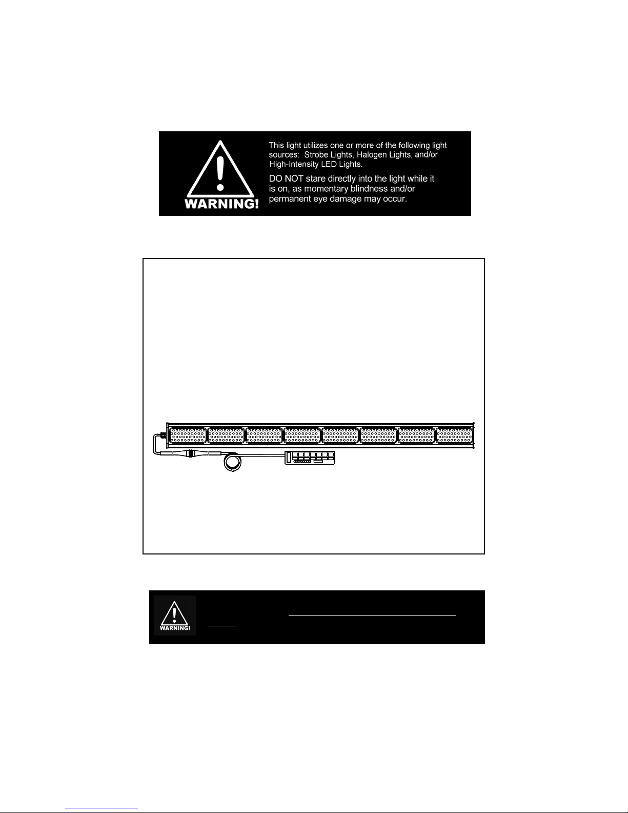
It is the sole responsibility of the owner to ensure the lightbar is
mounted securely. Check your light every time you enter the
vehicle to ensure that it is mounted securely. The manufacturer
assumes no responsibility for the secure mounting of this light.
Before beginning the installation:
- Determine where the Traffic Director is to be mounted (on your lightbar, on
your roof, in your rear window, etc.
- heck to see that there are no obstructions hindering the visibility of your
traffic director.
- Then select a location to mount your controller. The controller must be
located in a dry location out of direct sunlight, free of dirt and dust. Under the
vehicle's instrument panel is usually the best choice.
- Once you have selected these locations, determine the path your cable,
which connects the controller to the Traffic Director, will take. The cable
should exit the left side of the Traffic Director when you are facing both the
stick and the controller.
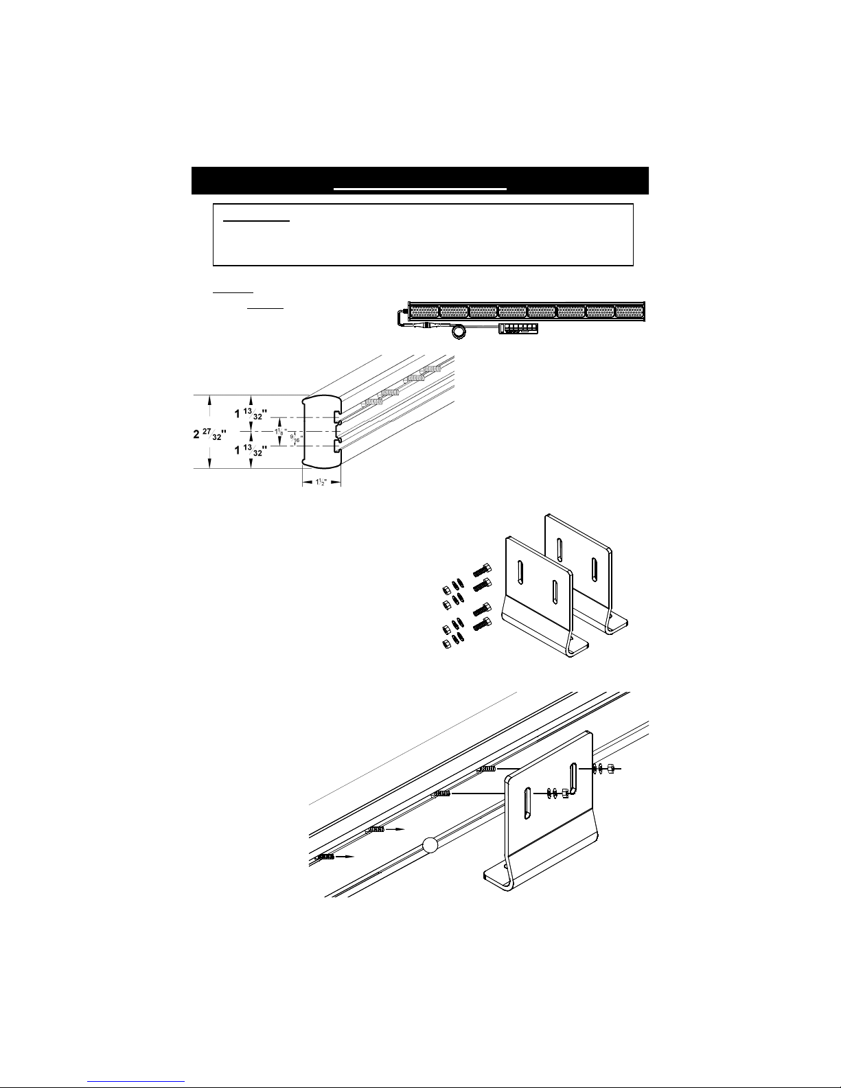
These traffic directors come with a short pigtail out of the side of the light that
attaches to the main harness. The available lengths for the harnesses are 15',
30', 45', and 60'. Be sure the harness you ordered is long enough for proper
installation. Star does not recommend “splicing in” additional cable when
the supplied cable is too short. If it is too short, you will need to order a
harness of the correct length.
-1-
Mount directly
to mounting
surface
OR Mount to
enclosed
L-Brackets
5. Slide the mounting bolts to their desired location (usually two bolts towards each end)
and mount the bolts through pre-drilled holes in your vehicle (for direct mounting)
or through the slots in the L-Brackets. Use a flat washer,
split washer, and nut on the bolt. You can mount
the L-Bracket with the base bending towards the
bar (as pictured below) or bending away
from the bar.
6. If you are using the L-brackets
provided, use the four
enclosed bolts or
other locally
obtained fasteners
to attach the L-
Brackets to your
mounting surface.
CAUTION: Be ure to carefully in pect and te t the integrity of your mount.
Plea e Note: These instructions are provided as a general guideline only. Some
vehicles may require special mounting wiring and/or weather-sealing. This is the
sole responsibility of the installer. Star Headlight & Lantern o., Inc. assumes no
responsibility for the integrity of the installation for this or any of its products.
1. Caution: There are two vapor vent holes drilled in the bottom of each endcap.
These are not visible, so be sure that
the cable exits the left side of the
Traffic Director when you are facing
both the stick and the controller.
Mounting Instructions
274-LLBK
2. Each Traffic Director assembly
comes equipped with two slots
that run along the entire length of
the rear of the extrusion.
The top slot will contain four
¼” x 20 x ¾” hex head bolts
pre-installed.
3. Two “L”-Brackets (274-LLBK) are included
with each traffic director to assist in
mounting.
4. Also included are four flat washers, four split
washers, and four nuts to attach the
L-Brackets to your traffic director.
In addition, there are four ¼” x 20 x ¾” hex
head bolts enclosed that can be optionally
used to mount the L-Brackets to your
mounting surface.
-2-
Electrical Connections
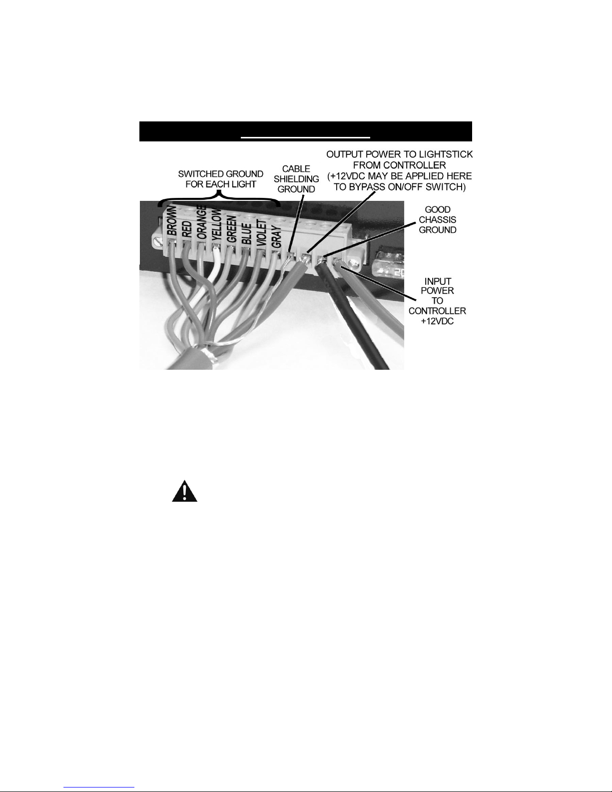
1. The cable attached to your Traffic Director should have a green connector (part # PSS-153)
attached to it. Eight colored 18 AWG wires, one bare drain wire, and a large red 12AWG wire
should already be connected from the cable to the connector.
2. onnect a ground wire to the interior empty terminal on the green connector. (See diagram
above) The corresponding terminal plugs into the outlet on the back of the controller and is
marked BAT-.
It is imperative that you supply a ground wire to the terminal marked
" AT -" on the controller. You must not let the controller's case supply
ground. Use 12 AWG wire for all power and ground connections
3. Supply power for the unit from a fused, +12 VD source capable of delivering at least 15
amps of current (use a 20 amp fuse). Star recommends the use of an ignition switched
supply to avoid the possibility of draining the vehicle's battery should the unit be
accidentally left on.
4. onnect your power supply to the terminal on the green connector that corresponds to
the outlet on the back of the controller marked BAT+.
5. The lamp brightness will be somewhat diminished if a large voltage drop exists between
the vehicle's battery and the controller. If voltage drop is a problem, use a relay to
control a direct battery feed. A generic relay designed for automotive lamp service
should be available from most automotive stores for this purpose. If using a relay, don't
forget to fu e the feed and ignal wire at their source, with appropriate values. It is
imperative that you supply a ground wire to the terminal marked "BAT -" on the
controller; you must not let the controller's case supply ground. Use 12 AWG wire for all
power and ground connections.
6. Your Traffic Director should now be ready to operate.
Please note: If you are connecting a TD93DLXT24 (which operates only on 24VDC) the
Input Power (and bypass power) would be 24VDC in the diagram above.
-3-
(Wiring CONT’D)
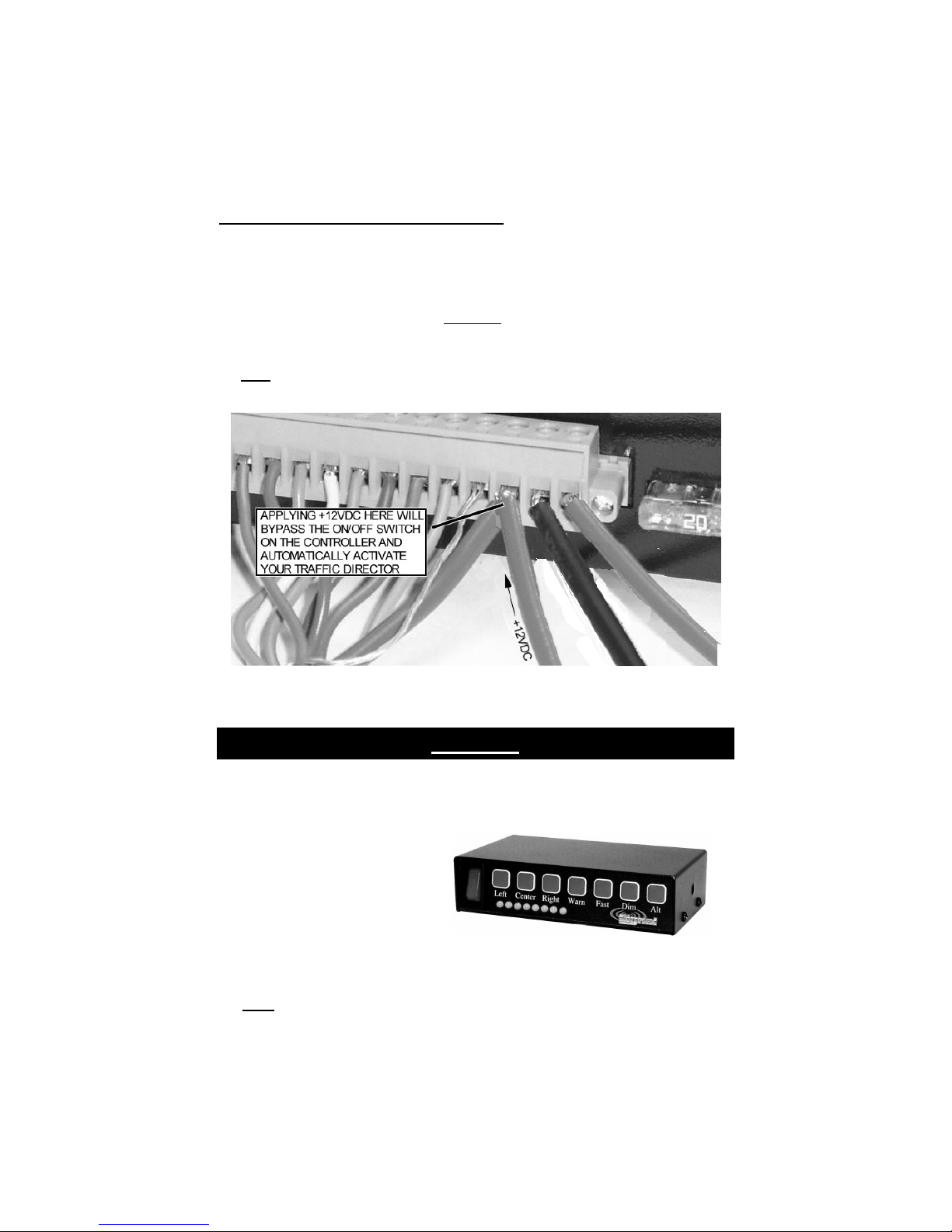
Wiring for Optional Automatic Activation
1. The Traffic Director may also be wired to automatically bypass the On/Off switch on the TD77-
NYDOT-2 controller and turn on through the use of an alternate power source (i.e. lightbar
switch, siren switch, reverse switch, etc.).
2. When you apply +12VD to the 12AWG wire supplying the stick with power, you will bypass
the On/Off switch and activate the Traffic Director. When activated, the Traffic Director will
automatically enter the "Warn" pattern. CAUTION: If any other lights are also connected to
this “bypass” circuit they will activate any time the traffic director is powered up unless
they are isolated in some way (e.g. diode or relay).
Note: If the “Alt” button was active when the unit was turned off it will be active when the unit
is turned back on.
TD77-NYDOT-2 Controller
Operation
1. Your new traffic director is a powerful tool that can aid you in traffic control; or if used
improperly, it could direct traffic into a dangerous situation.
USE CAUTION!!!
2. Operation of your Traffic Director is
straightforward. The controls
include an On/Off switch, four
Pattern Select buttons, and three
additional "option" buttons.
3. Turn the vehicle's ignition switch to the on or accessories position to supply power to the
controller (if necessary) and press the On/Off switch on the control box. The LED
display should begin to show the "Warn" pattern and the "Warn" label should glow red.
Note: If the “Alt” button was active when the unit was turned off it will be active when
the unit is turned back on.

-4-
(Operation CONT’D)
4. Select the desired pattern (if different from
the current pattern) by using any of the
Pattern Select buttons. The Pattern Select
buttons include Left Center Right Warn
and Alt (patterns shown to the right). The
selected pattern label should change to red
and the light output should mimic exactly the
display on the controller.
5. The TD77-NYDOT2 controllers also have two
"option" buttons: Fast and Dim.
Fast utton
(Left / Center Out / Right Patterns Only)
The "Fast" button provides the user with the option to
display the Left, enter Out, or Right patterns in a
"faster" mode. Pressing the "Fast" button once
should change the "Fast" label to red and speed up
the pattern. Pressing the button again will change
the "Fast" label back to green and revert the pattern
to the standard speed.
Dim utton
This button allows the user the option to dim the light
for nighttime operation. When the "Dim" button is
pressed once the "Dim" label will change from green
to red and the Traffic Director will dim slightly (50%).
Pressing it a second time will change the button back
to Green and return the Traffic Director to full
brightness.
6. To avoid possible damage, the controller should be
turned off prior to engine starting. It is possible,
though not likely, to confuse the controller if the
vehicle's battery is low and the engine is started with
the controller running. If you notice that the
controller's display shows something out of the
ordinary, simply push the power switch to the off
position and back on again. This should clear any
fault caused by improper voltage being supplied to
the unit.
7. Once your Traffic Director is installed, please test all
the patterns, options, and alternate versions to
familiarize yourself with the various patterns and the
operation of the controller.
LEFT
ENTER OUT
RIGHT
WARN
ALT
=OFF = ON
When using the Traffic Director, always be sure
that the pattern selected is appropriate for the
present hazard condition. The potential
danger in di playing an inappropriate
pattern cannot be over tated.

-5-
Service
The TD93-NYDOT uses state-of-the-art light Emitting Diode (LED)
technology. These lightsticks are comprised of eight segments of Ultra-Bright
LEDs that are operated in a multiplexed mode to efficiently produce light
output with lifetimes up to 100,000 hours. Under normal circumstances, you
will not need to replace any lights in these lightsticks.
Head Replacement
If there is a failure in one of the arrays, the array
can easily be replaced without removing the
lightstick from the vehicle. The replacement head
is a part #TD93DLXTRH-* (*=color).
TD77-NYDOT-2 Controller
The TD77-NYDOT-2 controller contains two ATO "blade-type" fuses located in the back of
the controller. The fuses are accessible from the rear of the controller. The 20 amp fuse
controls power to the bar light assembly, while the 5 amp fuse powers the controller. If the
20-amp fuse blows the controller will continue to function normally, however, the roof
lamps will not. It is important to note that under normal circumstances the only reason a
fuse will blow is because there is a fault in the system. If a fu e blow repeatedly it i a
ignal that omething i wrong. Do not replace a blown fuse with anything other than
the same amperage rating as marked on the rear panel of the controller; doing so may
damage the unit, or worse yet start a fire. Likely causes of blown fuses are improper
wiring, harness damage, and/or improper bulb type.
If you have any questions concerning this or any other product, please contact our
Cu tomer Service Department at (585) 226-9787.
If a product must be returned for any reason, please contact our ustomer Service
Department to obtain a Returned Materials Authorization number (RMA #) before you ship
the product back. Please write the RMA # clearly on the package near the mailing label.
LED FIVE YEAR LIMITED WARRANTY
The manufacturer warrants this LED light against factory defects in material and
workmanship for five years after the date of purchase. The owner will be responsible for
returning to the Service Center any defective item(s with the transportation costs
prepaid. The manufacturer will, without charge, repair or replace at its option,
products, or part(s , which its inspection determines to be defective. Repaired or
replacement item(s will be returned to the purchaser with transportation costs prepaid
from the service point. A copy of the purchaser's receipt must be returned with the
defective item(s in order to qualify for the warranty coverage. Exclusions from this
warranty include, but are not limited to, domes, and/or the finish. This warranty shall not
apply to any light, which has been altered, such that in the manufacturer's judgment,
the performance or reliability has been affected, or if any damage has resulted from
abnormal use or service.
There are no warranties expressed or implied (including any warranty of merchantability
or fitness , which extend this warranty period. The loss of use of the product, loss of time,
inconvenience, commercial loss or consequential damages, including costs of any
labor, are not covered. The manufacturer reserves the right to change the design of
the product without assuming any obligation to modify any product previously
manufactured.
This warranty gives you specific legal rights. You might also have additional rights that
may vary from state to state. Some states do not allow limitations on how long an
implied warranty lasts. Some states do not allow the exclusion or limitation of incidental
or consequential damages. Therefore, the above limitation(s or exclusion(s may not
apply to you.

Table of contents


