Star Headlight & Lantern DLQSMC-4 User manual

PLIT594-4 REV. REV. B 2/27/20
DLQSMC-4 Quick Stick
MULTICOLORED WARNING STICK
Please Note: These instructions are provided as a general guideline only. Specific
mounting and/or wiring, may be necessary and are the sole responsibility of the
installer. Star Headlight & Lantern Co., nc. assumes no responsibility for the
integrity of the installation for this or any of its products.
-1-
Before beginning the installation:
Decide where you are going to mount the warning stick (on your roof, in your
rear window, on the back of the vehicle, etc.).
Check to see that there are no obstructions hindering the visibility of your
warning stick.
Decide how you will be controlling the warning stick (using independent
switches, a siren controller, etc.).
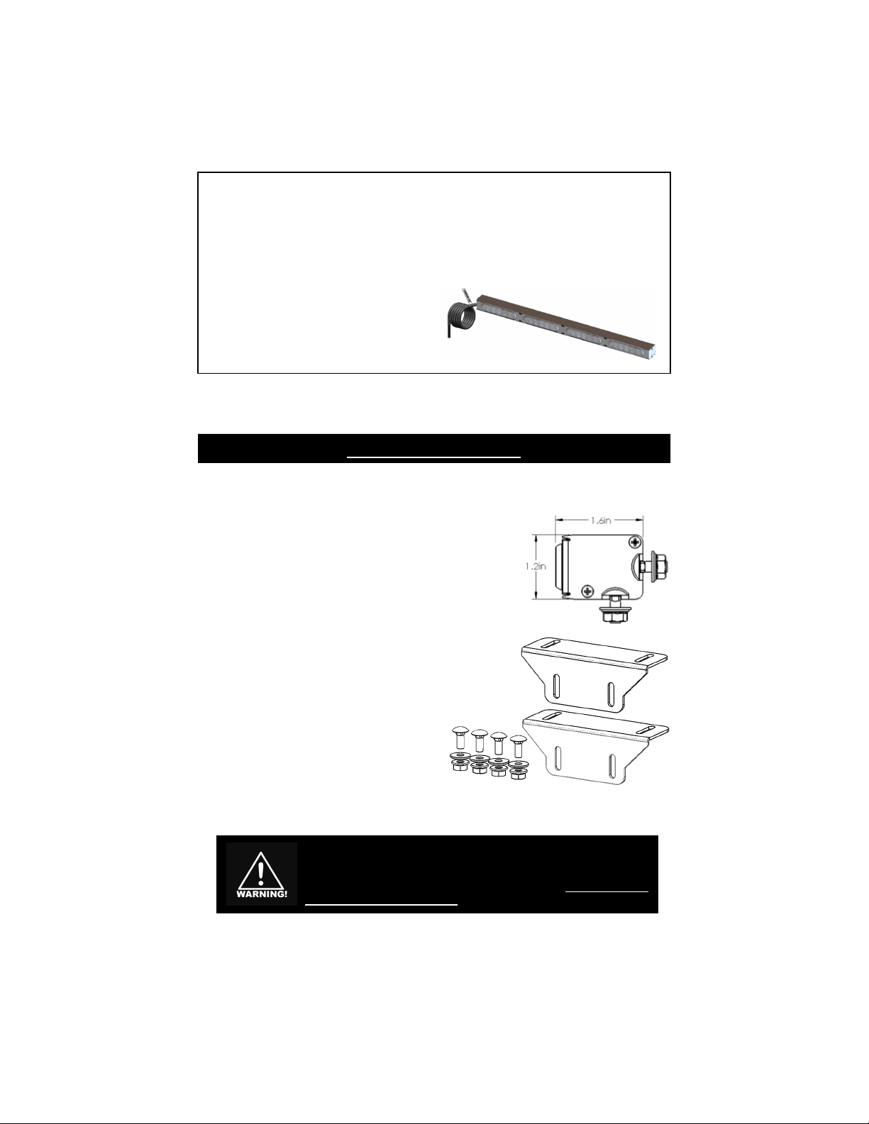
Choose a path your cable will
take. he cable should exit the
left side of the raffic Director
when you are facing the lights on
the stick.
Because of the wide variety of mounting applications, Star Headlight
& Lantern Co., Inc. assumes no responsibility for the secure
mounting of this light. It is the responsibility of the installer and or
owner to ensure the lightbar is mounted securely. Check your light
every time you use the vehicle to ensure that it is mounted securely.
1. here are two slots along the length of the
lightstick that can be used to facilitate mounting.
Depending upon your application, slide the two
enclosed #10 carriage bolts into the appropriate
slot (rear or bottom).
2. Slide them along the channel to the desired
location and mark the locations for your mounting
holes on the mounting surface.
3. Drill your holes and mount the light using the
enclosed washers and nuts.
We also include two L-Brackets to facilitate
mounting. hese are optional and do not need to
be used.
Mounting Instructions
-2-
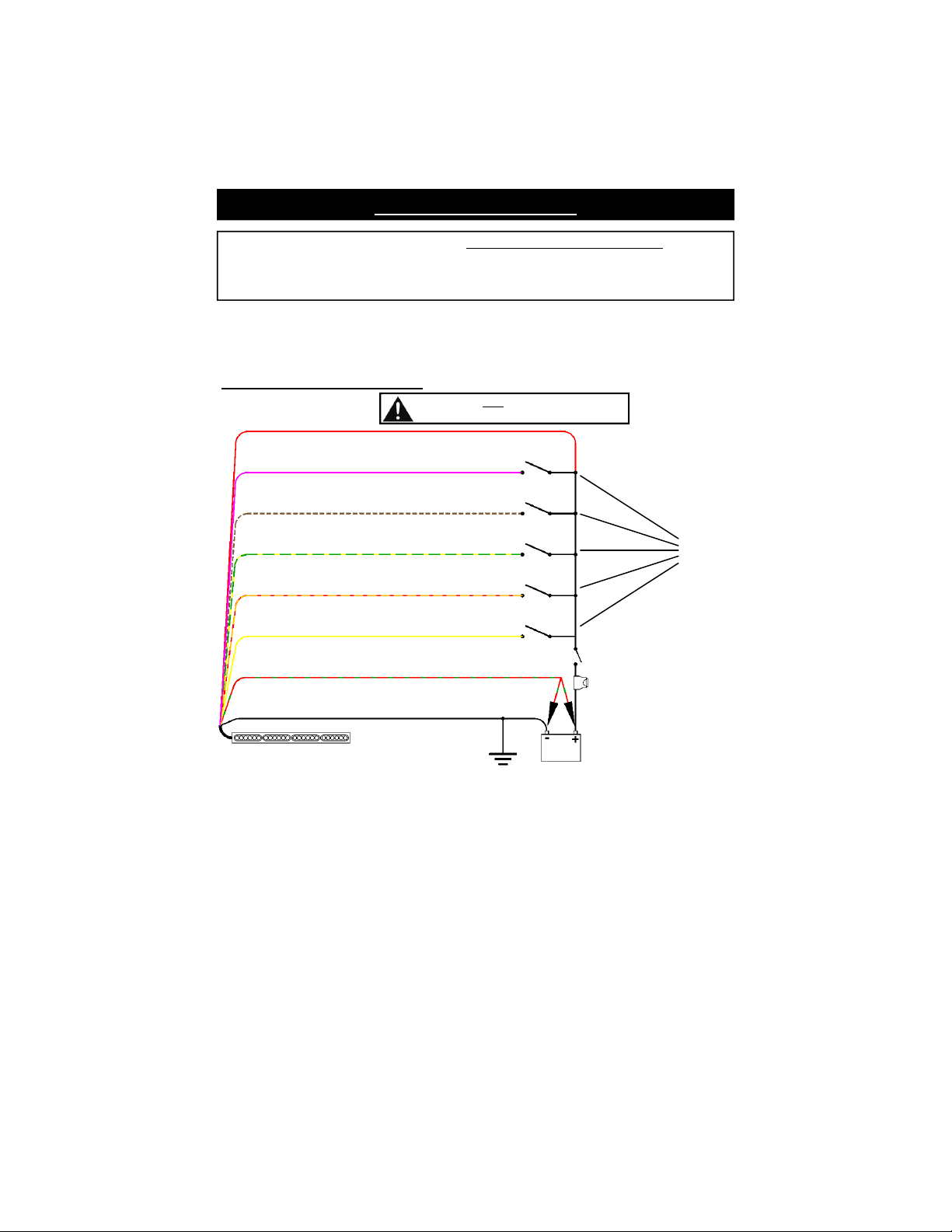
Electrical Connections
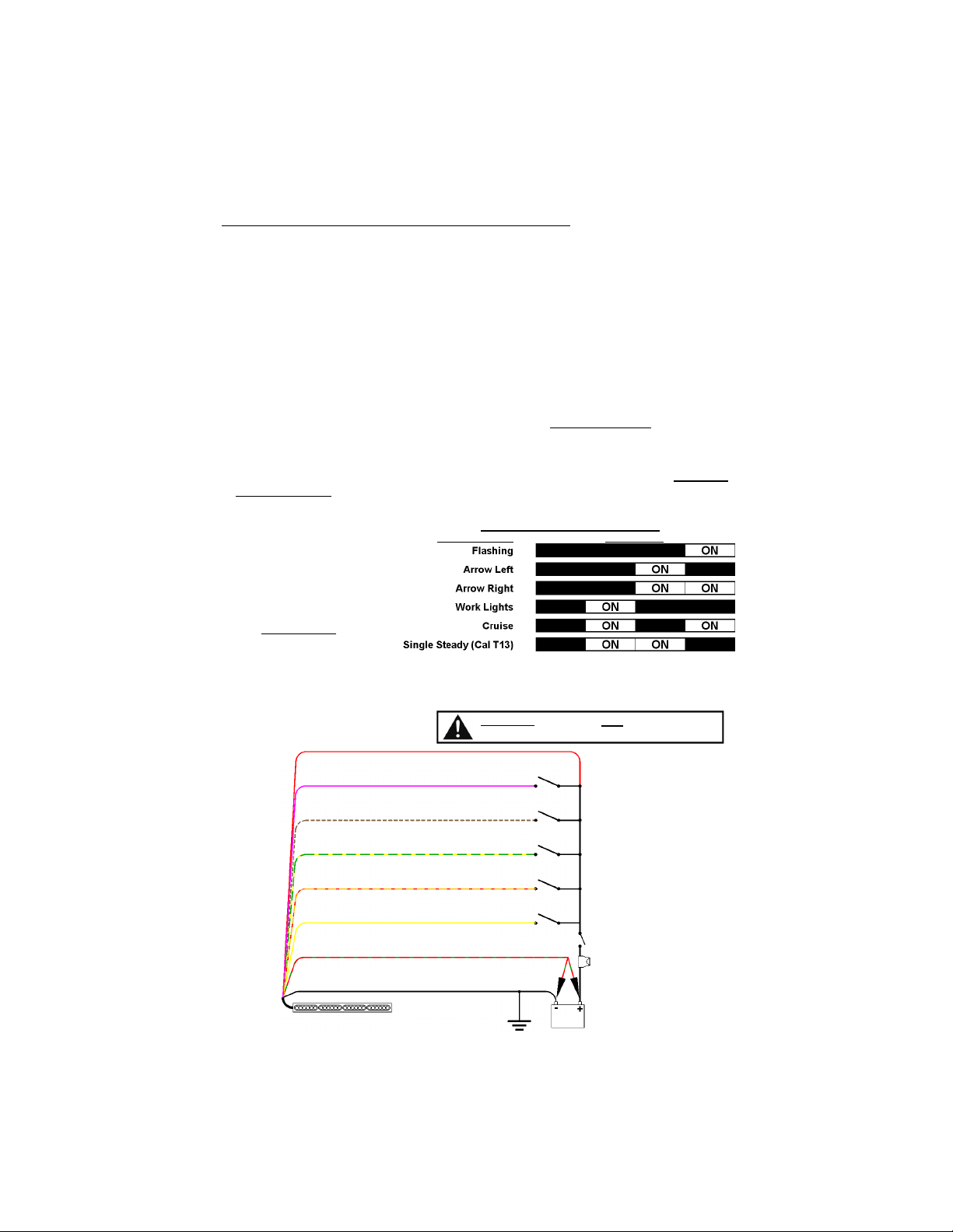
his wiring diagram below applies to the default programming of this light. here
are several additional advanced features that, if used, will affect the wire functions
shown below. Most applications will not require this reprogramming, but you can
find these options described in detail under the Advanced Programming section.
Note: The wires are shown above in order of Priority. igher priority wires will
override the patterns on any lower priority wires for the heads that are
enabled.
IG EST PRIORITY LOWEST PRIORITY
Pink > White w/Brown > Green w/Yellow > Orange w/Red > Yellow
Use standard On/Off switches rated for 5 amps and make your connections
according to the wiring diagram below.
Default Wiring Setup
(Wire Setup 3)
**Standby current < 0.001A
The RED wire must be connected to +12VDC
for any of the functions to work.
RED - Power
ORANGE w/RED - Dual Color Flashing / Warn
(PATTERN 18)
WHITE w/BROWN - Flashing / Warn Color 1
(typically amber -
PATTERN 1
)
GREEN w/YELLOW - Flashing / Warn Color 2
(PATTERN 1)
RED w/GREEN - Pattern or Phase Select
(See Pattern Programming)
BLACK - Ground
10 AMP use
Ignition-Switched Relay
12VDC BATTERY
YELLOW - Cruise
(Dim steady burn Color 1)
Default Wiring Setup
(Wire Setup 3)
PINK - Takedowns
(Bright steady burn Color 2)
unction
Wires

-3-
Standard Programming
Standard Programming Options
Flash Patterns for each Function
wire
Resetting the Factory defaults
his light has been designed for maximum versatility and has many different options
that can be programmed. his manual has divided the Programming into two
sections. Most users will not need to change any of the Advanced Programming
options.
Flash Pattern Programming
(Applies to Pink, White w/Brown, Green w/Yellow, Orange w/Red, and Yellow wires)
If you have any of your Function wires set for Flashing Mode, and you would like to
change the flash pattern, proceed below:
1. Connect the Red wire to power and the Black wire to Ground.
2. Connect one of the Function wires to +12VDC.
3. ouch and release the Pattern Select wire to +12VDC to scroll through the
patterns shown below.
Note: At any ti e you can shortcut to the pattern with the asterisk by holding the
pattern select wire to +12VDC for the indicated ti e.
4. Repeat the steps above to reprogram the pattern for the any of the other
Function wires.
Flash Patterns
1 Flicker * †
(factory default)
2 Slow Singleflash †
3 Fast Singleflash
Slow Doubleflash †
5 Medium Doubleflash †
6 Slow Tripleflash †
7 Fast Tripleflash †
8 Quadflash †
9 Quintflash †
10 Tripleflash w/Post Pop †
11 Quadflash w/Post Pop †
12 Quintflash w/Pre Pop †
13 Fast Doubleflash
1 Fast Quadflash
15 Singleflash Flicker
16 Doubleflash Flicker
17 Single, Quad w/Post Pop, Flicker
18 Dual-Color Single, Quad, Flicker
19 Dual-Color Quad w/Post Pop, Quint
20 Dual-Color Flicker
21 Delta-Omega
22 Random 1
23 Random 2
2 Random 3
25 Flashing Bounce
26 Full Bounce
27 Split Bounce
28 Half Bounce
29 Bounce w/End Pop
30 Search Lights
31 Eyeballz
32 Fade Invert
33 Moving Out
3 Triple In/Triple Out
35 Two Speed
(Pursuit default)
36 Random
* Shortcut Pattern #1 (3 sec/1 flash)
†
SAE Approved Pattern
Advanced Programming Options
Alternate Wire Setups
Custom Wire Programming
Priority Modification
Head Enable (which heads activate)
Single Steady Head Programming
Phase Selection (which heads
alternate from one another)

-4-
Operation
Using your user supplied switches, supply +12VDC to the wires indicated in the wiring
diagram on page 2 to activate the desired function.
Please note the following:
he Red wire MUS have +12VDC applied to it for any of the patterns to
work.
Higher priority wires will override the patterns on any lower priority wires for
the heads that are enabled.
IG EST PRIORITY LOWEST PRIORITY
Pink > White w/Brown > Green w/Yellow > Orange w/Red > Yellow
If two or more function wires that are set for flashing patterns 1-21 are
activated at the same time, the highest priority wire sets the pattern and
phase and enabled colors of the lower priority wire are added. For
patterns 22-36 or for steady burn functions, only the color on the higher
priority wire activates.
Service
Please be aware that the Quick Stick is designed with two internal connectors on
the harness that can be accessed by removing the two screws securing the
endcap and harness. his allows a Quick Stick that needs service to be removed
from the vehicle without needing to remove the entire harness.
If you do use this feature, it is imperative that the zip tie securing the connection be
replaced upon reinstallation to ensure that a good connection is maintained.
Because the connectors are inside the light stick, extra care must be taken so that
they are reinstalled properly. he installer is fully responsible for any issues that may
occur as a result of using the disconnect feature. his includes loose connections
and pinched wires.
Removing the Quick Stick From the arness
(Standard Programming CONT’D)
Resetting To Factory Defaults
If you ever need to reset the entire light to the Factory Default Settings, follow the
steps below:
1. Connect only the Red wire to power and the Black wire to Ground.
2. Hold the Pattern Select wire (RED w/GREEN) to +12VDC until the unit flashes three
times (~9 seconds - It will flash once, twice, then three times).
-5-
Advanced Programming
This section is OPTIONAL. Most applications will not require
any Advanced Programming. You should only need to
reference this section if you require specialized programming.
STOP !!
Advanced Programming Options
Alternate Default Wire Setups
Custom Wire Programming / Priority Modification
Includes Work Lights (bright steady burn), Cruise Mode (di steady
burn), and California Title 13 (single head steady burn)
Head Enable (which heads activate)
Phase Selection (which heads alternate from one another)
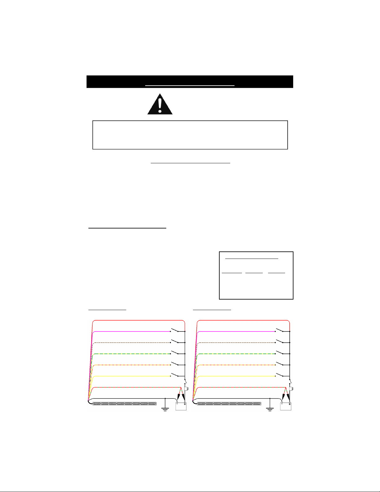
Alternate Default Wire Setups
he default wire setup is shown on page 2
(Wiring Setup 3)
. For ease of programming,
this light has been designed with three additional default setups. Follow the
instructions below and on the next page to reprogram the wires for Setup 1, 2, or 4.
1. Connect the Red wire to power and the Black
wire to Ground.
2. Hold the Pattern Select wire (RED w/GREEN) to
+12VDC then release it after the time indicated
in the chart to the right.
Wiring unction Setup
Hold # Wiring
Patt. Sel. Flashes Setup #
3 sec 1 Setup 1
6 sec 2 Setup 2
9 sec 3 Setup 3
12 sec Setup
Wiring Setup 1
ORANGE w/RED - Flashing/Warn
(Color 1 - PATTERN 8)
RED w/GREEN - Pattern Select
BLACK - Ground
YELLOW - Flashing/Warn
(Color 2 - PATTERN 8)
PINK - Cruise
RED - Power
WHITE w/BROWN - Left Arrow
(TD PATTERN STYLE 8)
GREEN w/YELLOW– Right Arrow
(TD PATTERN STYLE 8)
Wiring Setup 2
ORANGE w/RED - Dual Color
Flash
(Patt 1)
WHITE w/BROWN - Left Arrow
(TD PATTERN STYLE 1)
GREEN w/YELLOW - Right Arrow
(TD PATTERN STYLE 1)
RED w/GREEN - Pattern Select
BLACK - Ground
YELLOW - Cruise
PINK - Takedowns
RED - Power
-6-
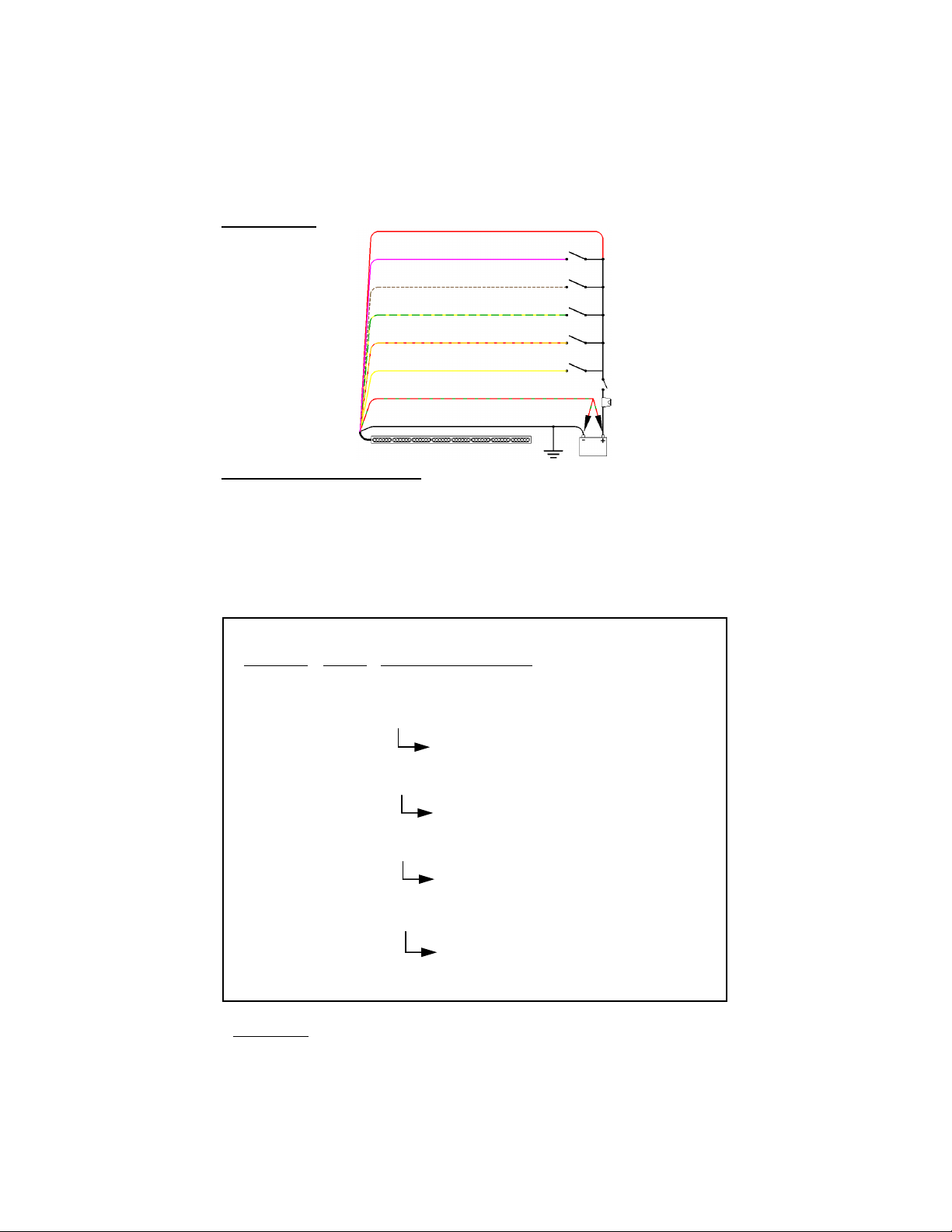
Programming Summary Chart
he chart below gives a quick overview of many of the programming options.
Pattern Incrementing and the Pattern 1 shortcut are discussed earlier in this manual.
he additional modes are described in further detail on the following pages.
1. Connect the Red wire to power and the Black wire to Ground.
2. Connect the function wire that you want to reprogram to +12VDC.
3. Select the option you wish to program and review the corresponding pages.
old
Red wGreen #
to +12VDC Flashes Programming Description
1 sec 0 Increments Pattern
(see pages 3-4)
3 sec 1 Shortcut to Pattern 1
(see pages 3-4)
6 sec 2 Custom Wire Programming Mode
ouch and release Red w/Green to Ground to
advance to desired options
(see page 8)
9 sec 3 Color 1 Head Enable Programming Mode
ouch and release Red w/Green to Ground to
scroll through Head Enable options
(see page 9)
12 sec 4 Color 2 Head Enable Programming Mode
ouch and release Red w/Green to Ground to
scroll through Head Enable options
(see page 9)
15 sec 5 Phase Programming Mode (see page 9)
ouch and release Red w/Green to Ground to
scroll through Phase options
(see page 10)
18 sec 6 oggles between Flashing Mode and Work Lights
(Ad anced Programming CONT’D)
Wiring Setup 4
PINK - Left Arrow
(TD PATTERN STYLE 8)
ORANGE w/RED - Flashing
(Color 2 - PATT 8)
WHITE w/BROWN - Right Arrow
(TD PATTERN STYLE 8)
GREEN w/YELLOW - Flashing
(Color 1 - PATT 8)
RED w/GREEN - Pattern Select
BLACK - Ground
YELLOW - Cruise
RED - Power
4. Save your programming by holding the Pattern Select wire to +12VDC until the unit
flashes once (~3 seconds), then releasing it.
-7-
Custom Wiring Setup
Use the diagram below to record the custom functions that you have programmed.
Please Note: The RED wire must be connected to
+12VDC for any of the functions to work.
ORANGE w/RED -___________________
WHITE w/BROWN - __________________
GREEN w/YELLOW - ________________
RED w/GREEN - Pattern or Phase Select
(See Pattern Programming)
BLACK - Ground
YELLOW - _________________________
RED - Power
PINK - ____________________________
Wiring unction Programming
Desired Function Stick Display
(Ad anced Programming CONT’D)
Custom Wire Programming and Priority Modification
Higher priority wires will override the patterns on any lower priority wires for the
heads that are enabled.
IG EST PRIORITY LOWEST PRIORITY
Pink > White w/Brown > Green w/Yellow > Orange w/Red > Yellow
If none of the 4 Wiring setups fits your needs (functions or priority of functions), you
can custom program each of the five input wires (Pink, White w/Brown, Green w/
Yellow, Orange w/Red, or Yellow) for any function (* Note: The Pink wire cannot be
reprogra ed for Flashing). Refer to the chart below and proceed as follows:
1. Connect the Red wire to power and the Black wire to Ground.
2. Connect the function wire that you want to reprogram to +12VDC.
3. Hold the Pattern Select wire to +12VDC until the unit flashes two times (it will flash
once, then twice - ~6 seconds), then release it, placing the light into Custo Wire
Progra ing Mode.
4. Reviewing the chart below, touch and release the Pattern Select wire to GROUND
(or Battery Neg) to scroll through the various options for each head. Use the
display of the heads of the lightstick to identify which function that function wire is
programmed for.
5. Repeat steps 2-4 for any other
function wires desired.
6. Save your programming by
holding the Pattern Select
wire to +12VDC until the
unit flashes once (~3
seconds), then releasing it.
-8-
ead Enable
his warning stick also has the ability to allow the installer to select which heads are
active for any given function. Some examples of this might include options such as
these:
urning one of the colors On or Off for a particular function
De-activating several heads for one of the functions to indicate less urgency
Changing the number of active heads in Worklight or Cruise modes
Changing the single steady head for the Single Steady Head mode
his option is programmed independently for each function and each color.
1. Connect the Red wire to power and the Black wire to Ground.
2. Activate the function you wish to program by connecting the corresponding wire
to +12VDC.
3. Place the light in ead Enable Programming Mode by holding the Pattern Select
wire to +12VDC for the corresponding amount of time depending upon which
color you would like to program: Color 1 - hree flashes (~9 seconds)
Color 2 - Four flashes (~12 seconds).
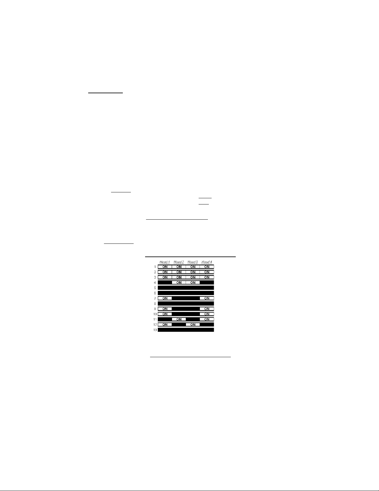
4. Scroll through the 13 optional variations below by touching and releasing the
Pattern Select wire to GROUND (or Battery Neg).
5. Repeat steps 2-4 for each function you wish to program.
6. Save your programming by holding the Pattern Select wire to +12VDC until the
unit flashes once (~3 seconds), then releasing it.
Flashing or Steady Head Enable Chart
(Ad anced Programming CONT’D)
Single Steady Head Programming
If you have programmed one of your function wires for the Single Steady Head
option (typically used for California itle 13 compliance) as described on the
previous page, you can change which head is steady by following the Head Enable
instructions above for either color and the corresponding function wire. Each time
you scroll the head will advance one position to the right, then cycle back around.

-9-
Phase Selection
(Programmable for Patterns 1-21 only)
Each head has two Phases, an “On” phase and an “Off” phase (or a “Color 1”
Phase and a “Color 2” phase). All of the heads/colors set for Phase 1 will illuminate
at the same time and flash opposite from all of the heads/colors set for Phase 2.
Prior to changing the Phase for any functions, please note the following limitations:
here are 10 different Phase options (shown in the chart below), allowing you to
customize which heads flash On together and which are Off together.
he Phase option is only compatible with Patterns 1-21. You cannot alter the
Phases for patterns 22-36 (the pre-set phase is crucial to the pattern).
1. Connect the Red wire to power and the Black wire to Ground.
2. Connect one of the Function wires to +12VDC, to activate that function.
3. Place the light in Phase Programming Mode by holding the Pattern Select wire to
+12VDC and releasing it after the unit flashes five times (~15 seconds - it will flash
once, twice, three times, four times, then five times).
4. Scroll through the 10 optional Phase variations (see chart below) by touching and
releasing the Pattern Select wire to GROUND. he stick will display each
corresponding Phase pattern as you scroll to it.
Holding the Pattern Select wire to Ground for 3 seconds (until it flashes once ) will
reset the Phase to the default setting.
Note: You are progra ing Phase 1 of Color 2. Color 1 (if enabled) will always
flash in Phase 2.
5. If applicable, repeat Steps 2-4 to program the Phase setting for the other Function
wires.
6. Save your programming by holding the Pattern Select wire to +12VDC until the
unit flashes once (~3 seconds), then releasing it.
(Ad anced Programming - Head Enable CONT’D)
(Factory Default)
-10-
NOTICE
Due to continuous product improvements, we must reserve the right to change an specifications and information,
contained in this manual at an time without notice. Star Headlight & Lantern Co., Inc. makes no warrant of
an kind with regard to this manual, including, but not limited to, the implied warranties of merchantabilit and
fitness for a particular purpose. Star Headlight & Lantern Co., Inc. shall not be liable for errors contained herein
or for incidental or consequential damages in connection with the furnishing, performance, or use of this manual.
If you have any questions concerning this or any other product, please contact
our Customer Service Department at (585) 226-9787.
If a product must be returned for any reason, please contact our
Customer Service Department to obtain a Returned Materials Authorization
number (RMA #) before you ship the product back.
Please write the RMA # clearly on the package near the mailing label.
LED IVE YEAR LIMITED WARRANTY
he manufacturer warrants this LED light against factory defects in material and workmanship for five
years after the date of purchase. he owner will be responsible for returning to the Service Center any
defective item(s) with the transportation costs prepaid. he manufacturer will, without charge, repair
or replace at its option, products, or part(s), which its inspection determines to be defective. Repaired
or replacement item(s) will be returned to the purchaser with transportation costs prepaid from the
service point. A copy of the purchaser's receipt must be returned with the defective item(s) in order to
qualify for the warranty coverage. Exclusions from this warranty include, but are not limited to, domes,
and/or the finish. his warranty shall not apply to any light, which has been altered, such that in the
manufacturer's judgment, the performance or reliability has been affected, or if any damage has
resulted from abnormal use or service.
here are no warranties expressed or implied (including any warranty of merchantability or fitness),
which extend this warranty period. The loss of use of the product, loss of time, inconvenience,
commercial loss or consequential damages, including costs of any labor, are not covered. he
manufacturer reserves the right to change the design of the product without assuming any obligation
to modify any product previously manufactured.
his warranty gives you specific legal rights. You might also have additional rights that may vary from
state to state. Some states do not allow limitations on how long an implied warranty lasts. Some states
do not allow the exclusion or limitation of incidental or consequential damages. herefore, the above
limitation(s) or exclusion(s) may not apply to you.

-11-
Other manuals for DLQSMC-4
1
Table of contents
Other Star Headlight & Lantern Work Light manuals

Popular Work Light manuals by other brands


Clark-Reliance
Clark-Reliance Jerguson LumaStar EPL-100 Installation, operation & maintenance instructions

General Manufacturing
General Manufacturing SAF-T-LITE 15 Watt Warranty & instruction manual

Philips
Philips GreenPower LED series Quick installation guide

Clarke
Clarke HLC400/110 Assembly & user instructions

Makita
Makita NLADML810 instruction manual

Eurotops
Eurotops FOCUS & WIDE instruction manual


