StarLogixs LiveTester LT-US User manual

Tester
Live
MODEL: LT-US (URD)
OPERATION MANUAL
COPYRIGHT © 2005
VOLTAGE DETECTOR

Content
1. Location of Control 3
2. Battery Fitting 3
3. Switching the Live Te ter On 3
4. Auto Power Off 4
5. Low Battery 4
6. Range Selection 4
7. Te t Key Selection 4
8. Static Di crimination 4
9. Multi Function Attachment 4
10. LiveTe ter URD Setting 4
11. Training & Safety 5
12. Operation 5
13. Application & Limitation 6
14. Intellectual Property 7
15. Specification 7
16. Warranty 8

•
E n u re b a tte rie a re fitted c o rre c t w a y a ro u nd
a h o w n a b ov e .
•
E n u re ba tte ry p ring i fitte d in b a tte ry ho ld e r.
•
P u h a n d ro ta te a h o w n to a tta c h .
3 . S w itc h ing the L ive T e te r O n
P re in g th e O N /O F F P o w e r K e y o n c e w ill w itc h th e u n it o n .
T h e L iv e T e te r w ill a lw a y w itc h o
n in th e 2 40 V ra n g e a nd
illu m in a tio n of th i L ED w ill ind ic a te th e p o w e r i o n .
P re in g the O N /O FF P o w e r Ke y a g a in w ill w itc h
th e u n it
o ff. T h i i in d ica te d b y a b rie f a u dib le b ee p a n d a fla h o f
th e w a rnin g lig h t.
2 . B a tte ry Fitting
1. L o ca tio n o f C o n tro l
3.

4. Auto Power Off
To provide maximum battery life the LiveTe ter will automatically witch it
elf off after a period of 30 minute . During thi 30-minute period a pre of
the keypad or alarm condition will re et the auto—power off timer, and the
30-minute period will recommence.
5. Low Battery
When the LiveTe ter i witched on and a low battery condition i detected
the Low Battery Indicator LED will illuminate. Before replacing the batterie
en ure that the problem i not being cau ed by a poor battery connection.
To do thi remove and replace the battery holder.
6. Range Selection
The LT-US(URD) LiveTe ter ha a wide voltage range acro which it can
operate. After the unit i witched on elect the correct range by pre ing the
Range Selector Key. Each time the Range Selector Key i pre ed the voltage
range increa e a indicated by the 11 Range Indicator LED’ . Pre ing the
Range Selector Key when the range i URD 25kV cau e the range to roll
back around to 240V.
7. Te t Key Function
Pre ing and holding the Te t Key will cau e the Beeper to ound
continuou ly and the Warning Light to be olidly on in any elected range, if
the unit i operating correctly.
8. Static Di crimination
The LiveTe ter ha unique circuitry that allow it to ignore electric field that
are not generated by a main ource (powerline ). Thi greatly reduce fal e
alarm and make the device uitable for patrolmen and re cue application
when et on the 240V range.
9. Multi Function Attachment
The unique multi-function attachment on the handle allow connection to
either a univer al fitting or a hotgun fitting with no loo e part .
10 LiveTe ter URD Setting
The URD etting are de igned to indicate the pre ence of voltage on a
capacitive te t point of a URD elbow. It will not provide reliable re ult on
hielded cable, buried cable or cable with concentric neutral . When
verifying URD te t point the indication di tance are typically 0.5 to 2
inche .
4.

11. Training & Safety
•
En ure you have carefully read thi manual and under tood all a pect
of the Live Te ter function.
•
Alway follow afety procedure and directive a publi hed by your
employer or local authority.
•
Alway wear rubber glove approved to ASTM D-120 pecification
rubber glove or/and ASTM F-711 hot tick .
•
Alway te t the LiveTe ter by pre ing and holding the Te t Key before
AND after the mea urement on the powerline i performed.
•
Never a ume a powerline will remain de-energized.
•
Alway fit earth jumper to the appropriate ASTM tandard.
12. Operation
Switch on the LiveTe ter and elect the correct range. Pre the Te t Key to
check for correct function of the unit.
Approach the conductor to be te ted with Detection Face. If the unit alarm
then the conductor i till live and no further te ting i required. If the unit
doe not alarm reduce the range voltage etting and repeat the te t.
Finally, recheck the function of the LiveTe ter by pre ing the Te t Key.
NOTES
1. If the LiveTe ter alarm indicating a conductor i live do not move the Detection Face clo er to the
conductor.
2. DO NOT touch high voltage tran mi ion line with the LiveTe ter, becau e an arc maybe
drawn from the line to the Te ter. Thi may cau e internal damage of the LiveTe ter circuit .
3. If Live/Dead indication of a low voltage line i being attempted in clo e proximity
to high voltage conductor , the detector may re pond to the high voltage line even though
the low voltage line i dead. Fixing the LiveTe ter at right angle to the hot tick and approaching the
low voltage line from the ide will help. The LiveTe ter i more en itive to electric field entering through
the Detection Face, and in thi configuration the electric field from the high voltage conductor will enter
through the ide of the unit to which it i le en itive.
CAUTION:
LiveTe ter i de igned ONLY to detect energi ed conductor in front of the
detection face. DO NOT u e ide contact to determine if a conductor i
energi ed.
5.

13. LiveTe ter Application and Limitation
Application :
LiveTe ter incorporate unique technology that allow it to make repeatable,
reliable mea urement in ituation where preexi ting non-contact detector
failed. Thi make the unit uitable for detecting:
•
Voltage leakage down the pole due to damaged in ulator .
•
Voltage leakage down earth wire from tran former ca ing , due to
failing tran former in ulation.
•
Patrolman work where energi ed high voltage conductor maybe
hazardou to per onnel.
•
Ground tep potential .
Limitation :
LiveTe ter i a non-contact detector and a uch depend on en ing an
electric field generated by an energized conductor. Electric field are ea ily
modified, and in ome ca e completely eliminated, in certain ituation by
the pre ence of conductor other then the energi ed conductor under te t.
The e other conductor can be either earthed or energi ed by another pha e
in the y tem . Operator hould be aware of the e effect , and take tep to
en ure the conductor to be te ted i approached in a part of the line where
no other conductor are clo e by. A good rule of thumb i to en ure all
other metal object are at lea t twice the di tance from the LiveTe ter, a the
di tance from the LiveTe ter to the conductor to be te ted. Al o it hould be
noted that an energi ed conductor laying on wet or dew covered or
ubmerged ground may till be energi ed, but po ibly will not be detected
by a non-contact detector. The moi ture di ipate the electric field.
LiveTe ter i not uitable for detecting armoured or hielded conductor ,
becau e the hielding prevent any electric field from e caping.
LiveTe ter i not uitable for detecting conductor energi ed with D.C. voltage
or at frequencie other than 50 or 60 Hz. That i it would not be uitable for
400Hz aircraft y tem , or D.C. railway y tem .
LiveTe ter i not recommended for detecting buried conductor .
6.

14. Intellectual Property
The content of thi document, LiveTe ter front panel artwork, printed circuit
board artwork, and firmware (program contained in integrated circuit ) are
ubject to copyright and can not be reproduced, tran mitted in any language
or computer language, in any form or any mean , electronic, mechanical,
optical, chemical, manual, or otherwi e, without prior written con ent from
StarLogix Pty. Ltd.
The Electric Field Detection Sy tem in the LiveTe ter i protected by
international patent . The Static Di criminator Sy tem i al o protected by
patent application .
The ymbol :
Tester
Live
are ubject to international trademark regi tration and their u e i
expre ly prohibited without written con ent from StarLogix Pty. Ltd.
15. Specification
Weight (no batterie ) 8.5oz (240g)
Dimen ion 11.3”L x 3.35”W x 3.35” H
(287mmL x 85mmW x 85mmH)
Environmental ealing IP65
Warning Light Inten ity 10,000 mCd
Warning Beeper Inten ity 80dB @ 3 Feet ( 1 Meter)
Power Supply 3 x C Cell Batterie
Battery Life
Standby (unit off) 10 year
(1)
On ( no alarm) 69 day
(1)
On (alarm condition) 18 day
(1)
Note:
(1) Battery life calculated u ing Eveready C Cell Energi er batterie with a
7,000mAh capacity down to 1.0V cell output.

W ARRANTY
Your StarLog ix LiveTe ter i g ua ranteed again t faulty
w orkma n hip or component for a p eriod of twelve month
after the p urcha e date. For warra nty conta ct your loca l
ale agent with proof of purcha e d a te.
Thi warra nty doe not cover damag e or fa ilure ca u ed by
or attributable to Act of God , ab u e, m i u e, improper
maintenance a nd tora ge, fla hover from high voltage
conductor to the LiveTe ter or any rep a ir other than tho e
provid ed b y a n authori ed StarLogix ervice facility, or
tra n porta tion co t .
Sta rLog ix i not re pon ib le or liable for indirect, pecial,
or con equential da m age ari ing out of or in conne ction
w ith the u e or p erform ance of the LiveTe te r or other
damag e with re pect to a ny econom ic lo , lo of
prop erty, lo of revenue or p rofit.
· Thi w a rra nty give you p ecific leg al right and you
may have other legal right w hich vary from tate
to tate.
8.
15.
16.
Table of contents
Popular Security Sensor manuals by other brands

Rielta
Rielta PYRONE-8B-RK installation guide
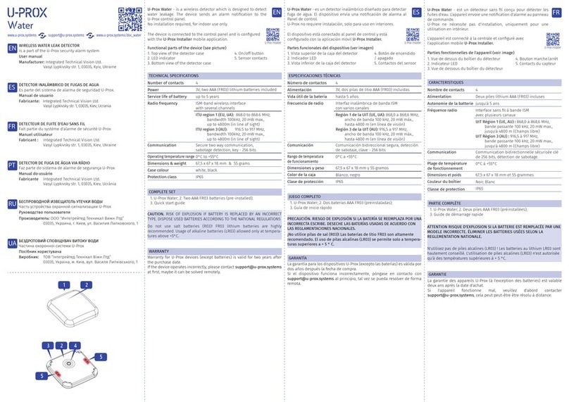
U-Prox
U-Prox Water user manual
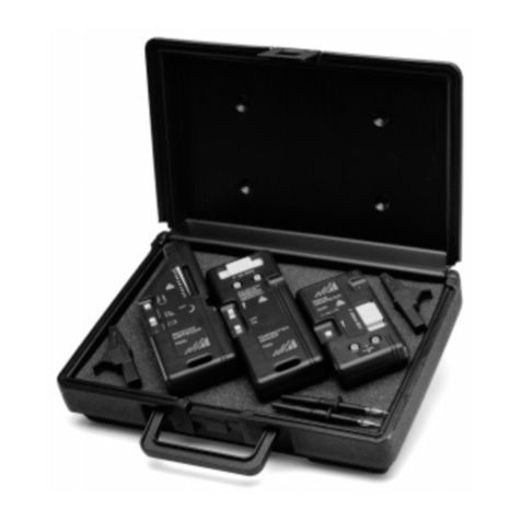
Gossen MetraWatt
Gossen MetraWatt Camille Bauer CableCop 300 operating instructions
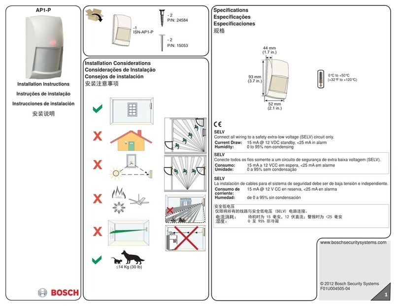
Bosch
Bosch AP1-P installation instructions
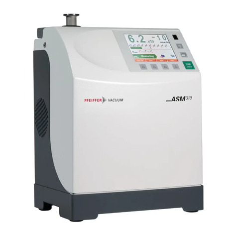
Pfeiffer Vacuum
Pfeiffer Vacuum ASM 310 operating instructions
Nobile
Nobile Smartmatic 9108011012 Mounting Operation Instruction
DualLite
DualLite SEWL Series Installation, Operation and Maintainance Instructions
STEINEL
STEINEL HF 3360 Information
Lince
Lince 1630DT/JOLLY Installation, Programming and Operating Instructions
Mastech
Mastech MS5905RTB manual
Satel
Satel AVD-100 manual

Markes International
Markes International C-HLD Instructions for use
