Gossen MetraWatt Camille Bauer CableCop 300 User manual

3.348.736.02
1/2.96
CableCop 300
Cable detection system
Operating Instructions
GOSSEN
METRAWATT
CAMILLE BAUER
GOSSEN
METRAWATT
CAMILLE BAUER

2GOSSEN-METRAWATT
Safety notes
Caution!
!Before you use the cable detection system CableCop 300, carefully read these op-
erating instructions and follow the generally relevant safety specifications according
to DIN VDE while operating the system.
When properly used, the safety of both the unit and the user is ensured.Their safety
is not ensured, however, if the unit is misused or carelessly handled
➭Before you use an electrical device, always make a performance test to verify that the de-
vice is operating properly.
➭Preferrably connect the signal generator S330 between phase and neutral. Before you
connect the signal generator between phase and neutral, absolutely check the ground re-
sistance according to DIN VDE 0100. With incorrect grounding, all parts connected to
ground could carry voltage should there be a fault.
➭Prior to connectingthe signal generator S330to current or voltage circuits, check that the
maximum permissible voltage for the signal generator is not exceeded.
➭Prior to connecting the transmitter T320, verify that the circuits or lines to be tested do
not carry current or voltage.
➭Avoid direct contact with non-insulated live lines. Eventually wear suitable insulating
gloves as well as goggles.
➭Disconnect the transmitter T320 from the measuring circuit before you replace the bat-
tery.

GOSSEN-METRAWATT 3
Contents Page
1 Applications, function principle . . . . . . . . . . . . . . . . . . . . . . . . . . . . . . . . . . . . . . . . . . 4
2 Description of the units . . . . . . . . . . . . . . . . . . . . . . . . . . . . . . . . . . . . . . . . . . . . . . . . 5
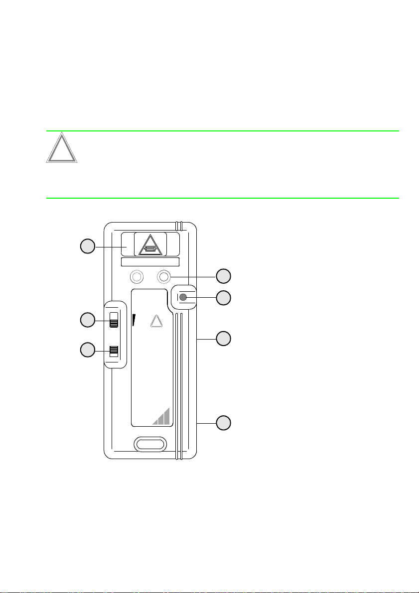
2.1 Receiver R300 . . . . . . . . . . . . . . . . . . . . . . . . . . . . . . . . . . . . . . .. . . . . . . . . . . . . . . . . . . . . . . . 5
2.2 Signal generator S330 for live lines . . . . . . . . . . . . . . . . . . . . . . . . . . . . . . . . . . . . . . . . . . . . .. . . 6
2.3 Transmitter T320 for electricallydead circuits . . . . . . . . . . . . . . . . . . . . . . . . . . . . . . . . . . . . . .. . . 7
3 Measurements on live lines with the signal generator S330 . . . . . . . . . . . . . . . . . . . . 8
3.1 Closed circuit mode . . . . . . . . . . . . . . . . . . . . . . . . . . . . . . . . . . . .. . . . . . . . . . . . . . . . . . . . . . . . 8
3.2 General procedures for live lines . . . . . . . . . . . . . . . . . . . . . . . . . . .. . . . . . . . . . . . . . . . . . . . . . . . 9
3.3 Locating switches, e.g. in building installations . . . . . . . . . . . . . . . . . . . . . . . . . . . . . . . . . . . . .. . 10
3.4 Locating lines in ceilings, walls and floors . . . . . . . . . . . . . . . . . . . . . . . . . . . . . . . . . . . . . . . . . . . 10
3.5 Locating short circuits between phase and protective conductor starting from a switchboard . . . . . . 11
3.6 Locating ground faults in three-phase systems . . . . . . . . . . . . . . . .. . . . . . . . . . . . . . . . . . . . . . . 12
3.7 Locating buried lines or underground cables up to a depth of approx. 3 m . . . . . . . . . . . . . . . . .. . 13
3.8 Tracing lines in conduits . . . . . . . . . . . . . . . . . . . . . . . . . . . . . . . . . . . . . . . . . . . . . . . . . . . . .. . 14
3.9 Tracing coaxial cables . . . . . . . . . . . . . . . . . . . . . . . . . . . . . . . . . . . . . . . . . . . . . . . . . . . . . . . . . 15
4 Measurements on electrically dead lines with the transmitter T320 . . . . . . . . . . . . . 16
4.1 Open circuit mode . . . . . . . . . . . . . . . . .. . . . . . . . . . . . . . . . . . . . . . . . . . . . . . . . . . . . . . . . .. . 16
4.2 General procedures for electricallydead lines . . . . . . . . . . . . . . . . . . . . . . . . . . . . . . . . . . . . . .. . 16
4.3 Locating lines and line interruptions in ceilings, walls and floors . . . .. . . . . . . . . . . . . . . . . . . . . . . 17
4.4 Tracing the entire building installation . . . . . . . . . . . . . . . . . . . . . . .. . . . . . . . . . . . . . . . . . . . . . . 18
4.5 Tracing water and heating pipe lines and conduits . . . . . . . . . . . . . . . . . . . . . . . . . . . . . . . . . . . . . 18
4.6 Tracing socket outlets and switches within the building installation . . . . . . . . . . . . . . . . . . . . . . . . . 19
4.7 Tracing bottlenecks in tubing or conduits . . . . . . . . . . . . . . . . . . . . . . . . . . . . . . . . . . . . . . . . .. . 20
4.8 Locating faults on an electric floor heating system . . . . . . . . . . . . . .. . . . . . . . . . . . . . . . . . . . . . . 21
4.9 Locating underground lines (also in the case of a broken cable) . . . . . . . . . . . . . . . . . . . . . . . . . . . 22
5 Technical Data . . . . . . . . . . . . . . . . . . . . . . . . . . . . . . . . . . . . . . . . . . . . . . . . . . . . . . 23
5.1 General information . . . . . . . . . . . . . . . .. . . . . . . . . . . . . . . . . . . . . . . . . . . . . . . . . . . . . . . . . . . 23
5.2 Receiver R300 . . . . . . . . . . . . . . . . . . . . . . . . . . . . . . . . . . . . . . . . . . . . . . . . . . . . . . . . . . . . . . 23
5.3 Signal generator S330 . . . . . . . . . . . . . . . . . . . . . . . . . . . . . . . . . . . . . . . . . . . . . . . . . . . . . . .. . 23
5.4 Transmitter T320 . . . . . . . . . . . . . . . . . . . . . . . . . . . . . . . . . . . . . . . . . . . . . . . . . . . . . . . . . . . . 23
6 Maintenance . . . . . . . . . . . . . . . . . . . . . . . . . . . . . . . . . . . . . . . . . . . . . . . . . . . . . . . 24
6.1 Battery . . . . . . . . . . . . . . . . . . . . . . . . . . . . . . . . . . . . . . . . . . . . .. . . . . . . . . . . . . . . . . . . . . . . 24
6.2 Fuse link . . . . . . . . . . . . . . . . . . . . . . . . . . . . . . . . . . . . . . . . . . . . . . . . . . . . . . . . . . . . . . . . .. . 24
7 Repair and replacement parts service . . . . . . . . . . . . . . . . . . . . . . . . . . . . . . . . . . . . 24

4GOSSEN-METRAWATT
1 Applications, function principle
The cable detection system CableCop 300 permits both electrically dead and live lines in cir-
cuits up to 300 V to be reliably detected. An interruption of the power supply, or a discon-
necton of equipment containing sensitive electronic parts, is not required. In particular, the
following applications are possible:
• Location of lines in ceilings, walls and floors
• Location of line interruptions, switches and fuses
• Location of short circuits
• Location of earth faults in three-phase systems
• Detection of bottlenecks in conduits
• Tracing of underground cables that are buried in the ground up to a depth of 3 m
• Tracing of conduits, water and heating pipe lines
• Sorting of installed lines
The cable detection system consists of a signal generator for live lines and a transmitter for
electrically dead lines as well as a receiver.
Signal generator and transmitter feed high-frequency electromagnetic signals into the line to
be tested. Along the line, these signals are converted into acoustical and optical signals by
the receiver. The signal strength is a measure for the location of the line.
Two basic operating modes are to be distinguished hereby:
Closed-circuit mode :
In this mode, live lines are tested with a potential of a maximum of 300 V to ground.
The signal current of the signal generator, for example, is fed into the phase of the line to be
tested and flows back to the signal generator through neutral conductor across the trans-
former. This "two-pole" application corresponds to a closed circuit, whereby the energy for
the generation of the signals is directly derived from the system.
In the case of a shorted line, the current flow in the circuit to be measured is interrupted, a 9-
V battery can, for example, be connected into the measuring circuit as a substitute power
supply.
The receiver evaluates the magnetic component of the signal.
Open-circuit mode :
In this operating mode, only electrically dead lines may be tested.
One output of the transmitter is connected to the line to be tested, the second output to
ground. This "single-pole" application corresponds to the principle of a radio transmitter. The
connected line hereby becomes the antenna of the transmitter, the ground serves as refer-
ence potential. The energy for the generation of the signals is provided by the internal bat-
tery.
The receiver evaluates the electrical component of the signal.

GOSSEN-METRAWATT 5
2 Description of the units
2.1 Receiver R300
The receiver R300 has two built-in detectors which receive the different signals from the sig-
nal generator for live and electrically dead lines.
These signals are indicated both optically and acoustically:
– Optically by a diode assembly with which up to 10 diodes light as a function of the signal
strength. A red filter permits reading also in the case of direct incidence of sunlight.
– Acoustically by a sound generator.
GOSSEN
METRAWATT
CAMILLE BAUER
GOSSEN
METRAWATT
CAMILLE BAUER
RECEIVER
EMPFÄNGER
R300
OFFx1
x10
x100
!
OFF
10
•
8
•
6
•
4
•
2
•
2
5
1
4
3
7
61Mode selector switch
– Open: for transmitter T320
– Closed: for signal generator S330
or for locating broken lines
2Thumb wheel
–ON/OFFswitch
– Vernier sensitivity setting
– Stop position highest sensitivity
3Standby LED
Lights provided the battery is inserted and
charged
4Range selector switch for coarse sensitivity
setting, amplification: 1, 10 or 100
5Diode assembly for indication of the signal
strength
6Detectors
7Battery compartment
The battery must be inserted with correct
polarity or else the compartment cannot be
closed.

6GOSSEN-METRAWATT
2.2 Signal generator S330 forlive lines
The signal generator S330 sends high-frequency electromagnetic signals which the sensor
R300 can locate along the line to be tested. For this purpose, the signal generator must be
connected to this line as well as to a return line. The signal generator is designed for lines
having AC or DC voltages from 9 to 300 V.
The signal power of this unit can be switched to a lower power so that circuits protected by
residual-current circuit breakers can also be connected.
GOSSEN
METRAWATT
CAMILLE BAUER
GOSSEN
METRAWATT
CAMILLE BAUER
SIGNAL
GENERATOR
S330
F 250mA 380V
max. 300V
9 - 300 V !
1
2
4
3
1Standby LED
Lights when the line is live
2Power selector switch
– Switch set to the top position: high power
– Switch set to the bottom position: low power
3Battery compartment
When withdrawn, the signal generator is
disconnected from the connected circuit
4Sockets for test leads

GOSSEN-METRAWATT 7
2.3 Transmitter T320 forelectrically deadcircuits
The transmitter T320 sends high-frequency electromagnetic signals the electric or magnetic
component of which can be detected along the line to be tested by the sensor R300. For
this purpose, one socket of the transmitter must be connected to this line. The second
socket must be connected to ground.
The unit requires a 9-V battery for the power supply.
An additional, external power source, e.g. a 24-V NiCd storage battery, leads to a increase in
performance.
Storage batteries in the battery compartment are not charged via the external power source.
Caution!
!The transmitter can only be used for electrically dead lines.
When using power supplies to increase the performance, only power supplies with
safe electrical isolation must be used.
GOSSEN
METRAWATT
CAMILLE BAUER
GOSSEN
METRAWATT
CAMILLE BAUER
TRANSMITTER
SENDER
T320
NUR FÜR SPAN-
NUNGSLOSE
STROMKREISE!
UNENERGIZED
CIRCUITS ONLY!
F 2A 250V
OFF
ON
!
1ON/OFF switch
2Standby LED
Lights provided a battery is inserted and
charged
3Power selector switch, three-stage
4Battery compartment
When withdrawn, the transmitter is
disconnected from the connected circuit
5Sockets for test leads
6Battery compartment
The battery must be inserted with correct
polarity or else the compartment cannot be
closed
7 Socket for external voltage supply for an
increase in performance
2
3
1
4
7
5
6

8GOSSEN-METRAWATT
3 Measurements on live lines with the signal generator S330
3.1 Closed-circuit mode
In this operating mode, live lines are tested with a potential having a maximum of 300 V to
ground.
The load current normally flows in the phase in opposite direction to the neutral conductor,
see connection A. This way, the also opposite magnetic fields are weakened, causing a loss
in signal strength in the receiver. The depth of detection is reduced. The same applies when
the current flows back across the protective conductor, see connection B.
This effect is eliminated by separating the current paths. While one socket is connected to
the line to be tested, the return line should not lie within the same cable or cable channel. As
a solution, apply the return line to a remote socket outlet via a cable-reel, the other one to a
separate ground such as, for example, central heating, water pipe line or sprinkler system.
AB
AB

GOSSEN-METRAWATT 9
3.2 General procedure for live lines
Signal generator
➭If the measuring circuit has no residual-current circuit breaker, select the highest signal
amplification.
Caution!
!Before you connect the signal generator to live lines, verify that not morethan 300 V
DC or AC voltage are applied.
➭Connect the sockets of the signal generator in line with the application at a time. The
diode of the signal generator must always light after connection of the test leads, other-
wise the measuring circuit is not closed and no current flows.
Receiver
➭Insert the battery.
➭Select the closed circuit mode.
➭First set the range selector switch 4 to the lowest amplification x1.
➭Switch the unit on by means of the thumb wheel 1 and set the vernier sensitivity to
stage 5. The standby LED must light.
Note
☞The sensitivity should generally be chosen in such a way that as much as possible a
medium range ofthe diode assemblyis controlled for measured signals (diodes 4 to
6 light). With control up to the tenth diode, signal fluctuations can no longer be val-
uated unambigously.
Alignment of the receiver when using the signal generator S330
The test head must be held vertical to the line as the electro-
magnetic component is to be captured when measuring on
closed circuits.
Here, the direction of the current is shown by arrows in the con-
ductor and the spreading direction of the electromagnetic com-
ponent by circular arrows.

10 GOSSEN-METRAWATT
3.3 Locating switches, e.g. in a building installation
➭Connection: Connect one socket of the signal generator to the neutral conductor, the
other one to the phase of the same socket outlet.
➭Locating: Hold the head of the receiver to every switch in the fuse box.
The associated switch is located by the strongest signal.
3.4 Locating lines in ceilings, walls and floors
➭Connection: Connect one socket of the signal generator to a separate ground, the
other one to the phase of the same socket outlet.
➭Locating: Move the head of the receiver in vertical direction along the point at which
you expect the line.

GOSSEN-METRAWATT 11
3.5 Locating short circuits between phase and protective conductor starting from a switchboard
Caution!
!Since voltage could be applied to the lines to be tested, act very carefully:
– First find out, whether voltage is applied in spite of the short circuit.
– When testing the voltage with the aid of the standby LED of the signal generator,
you always should connect the ground first.
– Only when there is no voltage applied:
Connect the signal generator and the auxiliary voltage source.
➭Connection: Connect one socket of the signal generator to ground, the second
socket to the phase via an auxiliary voltage source, e.g. a battery of at
least 9 V. A precondition for this is that the protective conductor of the
building installation is also grounded. Alternatively, one of the test leads
can be connected directly to the protective conductor of the building in-
stallation instead of to ground.
➭Locating: Move the head of the receiver in vertical position along the point at which
you expect the line. Follow the signal up to the point of the short circuit.
Here, the signal disappears as the signal current flows back to the signal
generator across the short circuit.
9V

12 GOSSEN-METRAWATT
3.6 Locating ground faultsin three-phase systems
Caution!
!Since voltage may be applied to the lines to be tested, act very carefully:
– First find out whether voltage is applied in spite of the short circuit.
– When testing the voltage with the aid of the standby LED of the signal generator,
you always should connect the ground first.
– Only when there is no voltage applied:
Connect the signal generator and the auxiliary voltage source.
➭Getting started: First test the voltages of the individual phases to ground. The phase hav-
ing the lowest voltage probably has a ground fault.
➭Connection: Connect the socket of the signal generator to a grounded AC or DC
power source, the other one to the faulty phase.
➭Locating: Move the head of the receiver in a vertical position along the point at
which you suspect the line. Follow the signal up to the point of the
ground fault. From here on, the signal gets weaker as the main portion of
the signal current flows back to the signal generator across the ground
fault.
e.g. 220 V~

GOSSEN-METRAWATT 13
3.7 Locating of buried lines or underground cables up toa depth of approximately 3 m
➭Connection: Connect the socket of the signal generator to a separate ground, e.g. di-
rectly toan auxiliary earth electrode, the otherone to the phase of the line
running underground.
In the case of an electrically dead cable, a DC or AC source can be con-
nected between socket and separate ground.
➭Signal generator: Switch the signal generator on and select the highest power.
➭Receiver: When searching for a line, proceed as described under "General proce-
dures for live lines" on page 9.
The soil has a minor influence on the generated magnetic field. The signal portion returning
via the limitedly conducting earth causes a weakening of the total signal strength to be
measured. The signal strength generally depends upon the horizontal position, the depth of
the cable, the conductivity of the soil as well as the type of soil.
Instead of a separate earth, a return line running above ground can be used, e.g. a cable-
reel. This way, the signal strength can rise by half.
Note
☞When using a separate above-ground return line, note that the distance between
forward and return line must be greater than the depth of the underground cable,
but at least 2 m.

14 GOSSEN-METRAWATT
3.8 Tracing lines in conduits
Note
☞Note that the magnetic field on the line to be tested can also influence neighbouring
conduits. That is why the receiver should be held at least 2 m away from the next
switch box.
Conduits of steel having thick walls attenuate the signal to be traced while conduits
of plastics or aluminium do not impair the signal.
➭Connection: Connect one socket of the signal generator to a separate earth, the other
one to a live line.
➭Locating: When searching for a line, proceed as described under "General proce-
dures for live lines" on page 9.

GOSSEN-METRAWATT 15
3.9 Tracing coaxial cables
➭Connection: Connect one socket of the signal generator to the shield of the coaxial
cable and the other one to a grounded DC or AC source.
➭Locating: When searching for a line, proceed as described under "General proce-
dures for live lines" on page 9.
Caution!
!Make sure that the shield of the coaxial cable is applied to ground potential on the
other end.
e.g. 220 V~

16 GOSSEN-METRAWATT
4 Measuring on electrically dead lines with the transmitter T320
4.1 Open circuit mode
Only lines carrying no current and no voltage must be tested in this operating mode.
Connect one output of the transmitter to the line to be tested, the second output to ground.
4.2 General procedures for electrically dead lines
Transmitter
➭Install the battery.
➭Select a medium signal amplification.
➭Switch the transmitter on. The standby LED must light.
Caution!
!Make sure that the line to be measured is electrically dead.
➭Connect the sockets of the transmitter in line with the application at a time.
Receiver
➭Install the battery.
➭Select the open circuit mode.
➭At first set the range selector switch 4 to the lowest amplification x1.
➭Switch the unit on via the thumb wheel 1 and set the vernier sensitivity to stage 5.
The standby LED must light.
Note
☞The sensitivity should generally be chosen in such a way that for the signals meas-
ured a medium range of the diode assembly is controlled (diodes 4 and 6 light). With
control up to the tenth diode, signal variations can no longer be valuated unambig-
ously.

GOSSEN-METRAWATT 17
4.3 Locating lines and line interruptions in ceilings, walls and floors
Caution!
!Make sure that the line to be measured is electrically dead.
➭Connection: Connect one socket of the transmitter toground, the otherone to the line
to be tested.
➭Transmitter: Switch the transmitter on and select the required power.
➭Receiver: Select the open circuit mode. When searching for the line, proceed as
described under "General procedures for electrically dead lines" on page
16. The signal strength decreases at the point of interruption and be-
yond.
Note
☞When searching for line interruptions in multiwire cables, note that all wires not used
must be grounded. This is to reduce capacitive couplings into the other lines. To lo-
cate the interruption, the transient resistance must be higher than 100 kΩ.
Note that the high-frequency signals for locating of lines are shielded in unfavourable
cases, e.g. by metallic foils or conduits.
Open measuring circuits
With open measuring circuits, the probe head must be held
horizontal to the line as the electric component of the signal is
picked up in this case.
Closed measuring circuits
With closed measuring circuits, the probe head must be held
vertical to the line. In this case, the magnetic component of the
signal is picked up.

18 GOSSEN-METRAWATT
4.4 Tracing the entire building installation
Caution!
!At first, disconnect the electric system on principle. *
➭Getting started: Remove the bridge between PE and N in the main distribution board.
➭Connection: Connect one socket of the transmitter to PE and the other one to the N
terminal in the main distribution board.
➭Transmitter: Switch the transmitter on and select the required power.
➭Receiver: Choose the open circuit mode. When searching for the line, proceed as
described under "General procedures for electrically dead lines" on page
16. You now can trace the neutral conductor in the entire building instal-
lation.
Caution!
!The connection between PE and N must absolutely be restored after the measure-
ment. *
4.5 Tracing water and heating pipe lines and conduits
Caution!
!At first, disconnect the electric system on principle. *
➭Getting started: Disconnect the pipes from the ground connection
➭Connection: Connect one test socket to ground, e.g. to the foundation earth elec-
trode or to the safety contact of the socket outlet, the other socket to the
corresponding pipe.
➭Transmitter: Switch the transmitter on and select the required power.
➭Receiver: Select the open circuit mode. When searching for the line, proceed as
described under "General procedures for electrically dead lines" on page
16.
Caution!
!The original ground connection must absolutely be restored after the
measurement. *
* Must only be performed by an expert who, based on his education, knowledge and experience as well
as the knowledge of relevant specifications, can understand the work he his charged with and who
can recognize eventual dangers.

GOSSEN-METRAWATT 19
4.6 Tracing socket outlets and switches within thebuilding installation
Caution!
!Disconnect the circuit by interruption in the distribution board.
➭Precondition: Neutral conductor and protective conductor each must be connected.
➭Connection: Connect one socket of the transmitter to the protective conductor, the
other one to the phase.
➭Transmitter: Switch the transmitter on and select the required power.
➭Receiver: When searching for the line, proceed as described under "General proce-
dures for electrically dead lines" on page 16.

20 GOSSEN-METRAWATT
4.7 Tracing bottlenecks in tubings or conduits
Caution!
!Disconnect existing circuits in the conduit. The circuits must be grounded.
➭Getting started: Disconnect the conduits from the ground connection
➭Connection: Connect one test socket to ground, e.g. to the foundation earth elec-
trode or the safety contact of the socket outlet, the other socket to the
metal spiral.
Instead of a metal spiral, a non- conducting spiral can be used with the
aid of which a copper wire can be pushed in up to the bottleneck.
➭Transmitter: Switch the transmitter on and select the required power.
➭Receiver: Choose the open circuit mode. When searching for the line, proceeed as
described under "General procedures for electrically dead lines" on page
16. The signal strength decreases at the bottleneck.
Bottleneck
Table of contents
Other Gossen MetraWatt Security Sensor manuals
Popular Security Sensor manuals by other brands

koban
koban KTF 8 instruction manual

Omron
Omron F3SG-4RA****-25-02TS series Quick installation manual

STEINEL
STEINEL Multisensor True Presence IP manual

ThermoFisher Scientific
ThermoFisher Scientific Vanquish VH-D10 operating manual

Honeywell
Honeywell C7007A installation instructions

REED
REED R9100 instruction manual