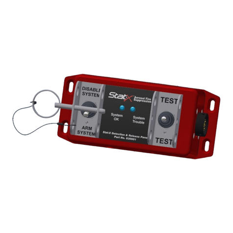
Stat-X 30E User manual

Electric Generator
Owner’s Manual
Version 1.2.5
August 2021
P/N 19001
Fireaway Inc. 5852 Baker Road • Minnetonka,MN 55345

Owner’s Manual
2 3
INTRODUCTION
Thank you for your purchase of a Stat-X®aerosol fire
suppression product. This brief manual is designed to
provide you with a general understanding of the product,
as well as, general information on installation, operational,
and maintenance parameters. It is not a detailed Design,
Installation, Operation, and Maintenance Manual. A detailed
manual may be obtained by contacting the manufacturer:
Fireaway Inc.
5852 Baker Road
Minnetonka, MN 55345
U.S.A.
www.statx.com
Stat-X systems and generators are to be installed and
periodically inspected by trained personnel ONLY. No
modifications are to be made to the installed system without
consulting a qualified system designer. The system is made
up of units tested within limitations contained in the detailed
Design, Installation, Operation, and Maintenance Manual. The
system designer must be consulted whenever changes are
planned for the system or the protected area. An authorized
installer or system designer must be consulted after the system
has discharged.
SYSTEM DESCRIPTION
General
Stat-X systems combine an environmentally safe fire
suppression agent, specially developed components, and fire
detection devices for rapid agent application. The resulting
timely suppression of fire may reduce property, facility, and
equipment damage. These systems are electrically operated,
are compact, and eliminate expensive pressure vessels,
nozzles, and distribution piping associated with other gas and
water based fire suppression systems. The Stat-X aerosol
agent is extremely effective when compared to alternative
agents and aerosol generators are strategically placed
throughout the hazard area offering significant weight and
space savings over conventional systems. Stat-X systems are
designed for total flooding applications in accordance with
established design criteria. All installations must meet the
requirements of the local authority having jurisdiction.
A single or connected group of Stat-X electrically operated units
(or generators) are used to suppress Class A (surface), Class B,
and Class C fires in specific hazard areas, facilities, or within
equipment located in enclosed areas and confined spaces
where low weight/space to extinguishing capacity is a factor.
The fire-extinguishing agent is an ultra-fine aerosol, which
hangs in suspension for extended periods of time (for at least
10 minutes) providing excellent protection against re-flash,
with minimal clean up.
Stat-X systems and generators are suitable for use in
normally occupied and unoccupied spaces. In areas
where personnel may be present the system shall employ
a pre-discharge alarm and 30 second time delay prior
to activation. Provision for system isolation for system
maintenance shall be provided when personnel may be in
the protected area.
They are intended to protect the following typical applications:
• Electrical Cabinets and Rooms
• Generator Rooms
• Glove Boxes
• Telecommunications Facilities
• Flammable Liquid Storage Areas
• Process Control Rooms
• Storage Vaults
• Marine Engine Rooms*
• Gas Turbine Enclosure
• High Value Mobile Equipment*
• Power Plants
• High Value Industrial Equipment Areas
*Not part of the UL Listing under UL Subject 2775 but are
covered under other applicable listings (American Bureau of
Shipping, Marine and Coast Guard Agency, ECB, and others)
Stat-X generators are not suitable for the following
hazards; or, where the following materials may be present:
• Materials, which burn with deep-seated characteristics
(wood, fiber, cotton, etc.)
• Electrical equipment operating at over 40,000 V
• Metal hydrides, pyrophoric substances, and chemical
substances that smolder and burn without air
• Metal powders (magnesium, titanium, etc.)
• Environments which require devices specifically listed/
labeled for installation inside rated hazardous areas
(explosive atmospheres).*
*Stat-X products suitable for use in classified hazardous areas
are listed separately under UL File No. E495772.
Extinguishing Agent
The aerosol produced upon activation of a Stat-X generator
suppresses fire by a combination of chemical and physical
mechanisms similar to the Halons without negative effect on
the environment. Because of the aerosol’s ultra-fine particle
size (≤2 micron) there is a dramatic increase in the surface
area interaction between the agent and the fire.
Unlike gaseous agents the aerosol does not decompose in the
presence of fire nor does it extinguish by oxygen deprivation.
The aerosol is considered non-toxic to humans when applied
in normal design concentrations necessary to extinguish most
fires; however, certain safety restrictions should be observed
when applying and handling the generators. Exposure to the
aerosol should be limited and unnecessary exposure to the
particulate should be avoided. Exposure to the aerosol is
generally less concerning than exposure to the decomposition
products of a fire.
Toxicity: Tests conducted by Charles River Laboratories
(Tranent, Scotland) as well as others have shown that the
aerosol does not present a health hazard due to limited
accidental exposure at normal design concentrations.
Exposures under five minutes are normally considered safe.
While the components of the aerosol are not considered toxic at
normal concentration levels, ingestion of the ultra-fine particulate
may cause short-term discomfort and unnecessary exposure
should be avoided. Tests have shown no long-term negative
effects from exposure to the aerosol. In addition, the aerosol has
a high obscuration factor. US EPA has approved Stat-X for use as
a total flooding system for normally occupied spaces.
NOTE
STAT-X SYSTEMS SHALL ONLY BE APPLIED IN AREAS
WHERE PERSONNEL MAY BE PRESENT IN CONJUNCTION
WITH A 30-SECOND TIME DELAY TO ENSURE EGRESS OF
PERSONNEL PRIOR TO SYSTEM DISCHARGE. A SYSTEM
MAINTENANCE ISOLATE SWITCH SHOULD BE INSTALLED IN
NORMALLY OCCUPIED AREAS.
Residue and Cleaning: The ultra-fine aerosol discharge
remains in suspension for an extended period and can be
vented by a fan or air handling system. Aerosol residue, which
may have settled on the floor, equipment, or other surfaces,
can be vacuumed or wiped clean with a water & acetic acid
solution (e.g. vinegar). Settled and agglomerated particulates
following an aerosol discharge is initially deliquescent in
spaces with high humidity and is soluble in water.
Other Safety Considerations: The aerosol discharged into
the hazard area upon activation of the generator is relatively
“cool.” However, the aerosol stream as it leaves the generator
is above 100°C for a short distance from the outlet of the
generator. Maximum temperatures are realized only in the last
seconds of discharge. Each model has a required installation
clearance distance specified as its “C-Zone.” Steps must
be taken to ensure generator placement so that it complies
with this installation requirement. The generator housing is
approximately 90°C immediately after discharge and care
should be taken if handling the post-discharge generator prior
to its cooling to ambient temperature.
Generators must never be installed to discharge directly
on walls or equipment being protected, as this will cause
agglomeration.
Storage: Each Stat-X aerosol generator is sealed with a
non-permeable membrane and is unaffected by fluctuations in
temperature and humidity. Accelerated aging tests have shown
the generator’s charge maintains its viability for more than
15 years under conditions ranging from - 40°C to + 54°C and
cycled relative humidity levels up to 95%.
Owner’s Manual
4 5
Operating/Temperature Range: Stat-X aerosol generators
are listed to operate within a temperature range of -40°C to
+54°C/-40ºF to 129.2ºF. Generators are sealed with a non-
permeable membrane and are unaffected by fluctuations in
humidity and temperature.
EQUIPMENT INSTALLATION
General. All Stat-X generators must be installed to facilitate proper
operation, inspection, testing, and any other maintenance as may
be necessary. Equipment must not be subject to mechanical,
chemical, or other damage, which could render the unit inoperative.
Equipment must be installed in accordance with all applicable
standards and the contents of this section of the manual.
WARNING
AEROSOL GENERATORS CONTAIN A FLAMMABLE SOLID
AND MUST ONLY BE HANDLED, INSTALLED, AND SERVICED
BY A TRAINED TECHNICIAN USING THE INSTRUCTIONS
CONTAINED IN THIS SECTION. FAILURE TO FOLLOW THESE
INSTRUCTIONS COULD CAUSE A PREMATURE DISCHARGE
AND/OR POTENTIAL INJURY.
Aerosol Generator Installation. The Stat-X aerosol generators
should normally be located within the protected hazard area.
The following installation instructions must be followed in
the exact sequence outlined below to prevent accidental
discharge, bodily injury, or property damage.
WARNING
TO PREVENT PERSONAL INJURY, DE-ENERGIZE ALL
ELECTRICAL CONNECTIONS PRIOR TO GENERATOR
INSTALLATION.
Single Generator System:
1. Position mounting bracket and securely fasten to wall,
ceiling, or other supporting structure in a location and
manner, which ensures the generator will not be subjected to
accidental damage or movement.
2. Remove generator from shipping container and inspect
integrity of the non-permeable membrane and generator. Do
not install if the membrane is ruptured in any way or if the
housing has been damaged in shipment. Verify igniter integrity
with Ohmmeter. Do not install if reading > 2 ohms.
3. Securely attach generator to the mounting bracket with
generator clamp taking care to ensure the clamp is free of the
initiator mechanism and that all bolts are securely tightened.
4. Position generator, via the bracket-mounting swivel, to
allow for an unimpeded discharge upon activation. Care must
be taken so that the generator does not directly discharge
at close range at the wall, ceiling, or vertical surfaces of the
equipment within the hazard area.
5. Taking care to ensure that power is off, connect electrical
lines to the initiator fitting at the top of the generator.
NOTE
THE INTERFACE BETWEEN THE GENERATOR AND THE
FIRE ALARM CONTROL PANEL MAY REQUIRE ADDITIONAL
ELECTRICAL DEVICES TO MEET LISTING COMPATIBILITY
REQUIREMENTS. CONSULT FIRE ALARM CONTROL PANEL
MANUAL FOR ANY LISTED SPECIAL FIELD DEVICES THAT
MAY BE REQUIRED AS PART OF THE RELEASING CIRCUIT
(E.G. EMATCH PROTECTION DEVICE, P/N 3005014).
WARNING
DE-ENERGIZE ALL ELECTRICAL CONNECTIONS PRIOR TO
GENERATOR INSTALLATION. BE CAREFUL TO ENSURE THAT
NO BODY PART IS PLACED DIRECTLY IN FRONT OF THE
GENERATOR’S EXIT PORTS DURING INSTALLATION.
Multiple Generator System:
1. Position mounting brackets and securely fasten to wall,
ceiling, or other supporting structure in a location and
manner, which ensures the generators will not be subjected to
accidental damage or movement.
2. Make sure mounting brackets are located in a manner to
ensure a circular flow pattern and maximum dispersal and
mixing of aerosol and air during discharge.
3. Remove generator from shipping container and inspect
integrity of the non-permeable membrane and generator. Do
not install if the membrane is ruptured or punctured in any
way or if the housing has been damaged in shipment. Verify
igniter integrity with ohmmeter. Do not install if reading is
outside a range of 1.4 – 2.0 ohms.
INSTALLATION
Facility Considerations
Significant Obstructions/Agent Distribution: In cases where
there is a large ratio of fixed equipment to total volume, or
where the protected equipment is located in such a way as
to present a barrier to the free flow and distribution of aerosol
throughout the hazard area, the use of a larger number of
smaller aerosol generators may be more suitable. This will allow
for strategic placement of the aerosol generators and improved
distribution characteristics throughout the protected area.
Mounting: Stat-X aerosol generators are listed for both
sidewall and ceiling locations and may be mounted on
walls, beams, constructions, and columns, as long as the unit
is securely bolted to the support structure and is mounted in a
position where its “C-zone” (clearance zone where momentary
peak temperature of the discharge will not exceed 75°C) will
not impact on personnel, facilities, equipment or combustible
materials located within the protected area. Housing clearance
is required spacing of generator from combustibles and
structural materials.
Aerosol Stream Characteristics
Housing
Model C - Zone Height Max. Clearance
30E 0.25m/9.8" 0.5 to 1.22 m/19.7-48.0" 7mm/0.25"
60E 0.35m/13.8" 0.5 to 2.00 m/19.7-78.7" 7mm/0.25"
60ME 0.30m/11.8" 0.5 to 2.00m/19.7-78.7" 7mm/0.25"
100E 0.46m/18.1" 0.5 to 2.50 m/19.7-98.4" 13mm/0.50"
250E 0.75m/29.5" 0.5 to 2.75 m/19.7-108.3" 13mm/0.50"
500E 1.27m/50.0" 0.5 to 3.50 m/19.7-137.8" 13mm/0.50"
1000E 2.30m/90.6" 0.5 to 4.88 m/19.7-192.1" 13mm/0.50"
1500E 2.00m/78.7" 0.5 to 4.88 m/19.7-192.1" 30mm/1.00"
2500E 2.70m106.3" 0.5 to 4.88 m/19.7-192.1" 30mm/1.00"
Mounting Height: In general, the aerosol generators should
be mounted at or near ceiling height and angled toward the
floor at an angle to ensure three-dimensional distribution of
aerosol and an unobstructed discharge path. (15° - 30° for
sidewall mounting). To ensure maximum distribution of aerosol
throughout the hazard area, the maximum height of generator
placement from the floor must be limited as indicated above.
Underfloor applications should be mounted horizontally.
Flow: Placement of the aerosol generators to ensure proper
aerosol flow and distribution is extremely important as each
generator functions as a flow nozzle. Aerosol generators
must never be positioned to discharge directly at each
other! This will cause agglomeration of the aerosol particulate,
reducing the aerosol’s extinguishing effectiveness. For the
same reason, aerosol generators must be positioned to
ensure that the aerosol stream does not impinge directly
on walls or the sides of equipment being protected.
Typical Placement
Aerosol Generators
Equipment
C Zone
S
*
Equipment
Equipment
*Spacing “S” should be even unless prevented by obstruction.

Owner’s Manual
6 7
4. Securely attach generators to the mounting brackets with
generator clamps taking care to ensure the clamps are free
of the initiator mechanism and that all bolts are securely
tightened. Aerosol gases discharged from the generator
will add thrust loading on the clamps. It is essential that
the fasteners are secure.
5. Position generators, via the bracket-mounting swivel, to allow
for unimpeded discharge upon activation. Care must be taken
so that the generator does not directly discharge at close range
on the wall, ceiling, or vertical surfaces of equipment within the
hazard area. Generators must be positioned to promote circular
flow and mixing of aerosol from multiple generators. Aerosol
generators must never be positioned to discharge directly
at each other! This will cause agglomeration of the aerosol
particulate, reducing the aerosol’s extinguishing effectiveness.
The aerosol system is designed to flood the protected space
when the generators are positioned in a balanced arrangement.
It is not required for the generators to be aimed at specific
hazards as local application streaming devices.
6. Generators can be wired in series or parallel to a releasing
control panel. Activation current must be supplied to each
generator as follows:
Activation parameters of the initiator are:
• Resistance: 1.4 – 2.0 Ohms
• Minimum parallel circuit firing current: 0.5A for 0.050
seconds.
• Minimum series circuit firing current: 1.0A for 0.050
seconds.
• Specified maximum test current: ≤0.025A.
• Specified maximum supervisory current: ≤.005A.
7. Install releasing control panel, detection, and ancillary
devices per the directions contained in the manual supplied.
Wiring is to be installed to local code requirements.
8. Once the electrical components of the system have been
installed and tested, ensure power is off and then connect
electrical lines to the initiator fitting at the top of the generator.
Post Installation Checkout: After the Stat-X generators have
been installed and connected to the appropriate detection and/
or control system perform the following inspection and tests.
1. Verify generators of the correct size are installed per the
installation drawings.
2. Verify generator mounting brackets and clamps are properly
installed and that all fittings and fasteners are tight.
3. Verify electrical connections have been made and test for
electrical continuity using an ohmmeter.
4. Verify generators are positioned properly. Check for
obstructions in the path of the aerosol discharge stream.
Generators must be installed such that they cannot cause
personnel injury upon activation. The aerosol discharge stream
must not impinge at close range on walls, ceiling, or equipment.
5. Manual/electrical release stations must be properly
installed, readily accessible, and clearly identified.
6. Verify time delay functionality and integrity.
7. All acceptance testing shall be in accordance with this
manual, any applicable standards, and the authority having
jurisdiction.
OPERATION
General. A solid charge of the aerosol composition is
contained within the sealed generator. Upon activation of the
initiator, the charge begins a controlled burn producing an
ultra-fine aerosol. The aerosol passes through an oxidation
filter, where CO is converted to minor amounts of CO2, and
then through a cooling bed where the temperature of the
aerosol is rapidly reduced before it escapes through the
discharge ports of the generator at low pressure. Generator
placement within the hazard area provides proper flow and
distribution of the aerosol within the protected area.
Operating Procedures
Electrical Automatic Operation: Electrical automatic
operation occurs upon activation of the detection circuit,
initiating a voltage source from the fire alarm control panel to
the generators.
In areas where personnel may be present, a 30 second
time delay is required to ensure egress time prior to system
discharge. In normally occupied areas, a system maintenance
isolate switch shall be installed outside the hazard area to
ensure that activation of the system is “manual only” during
maintenance of the system.
Personnel must evacuate the hazard area promptly upon
hearing the pre-discharge alarm. Ensure no one enters
the hazard area after discharge and call the fire
department promptly.
NOTE
THE ABOVE INSTRUCTIONS MUST BE POSTED ON DISPLAY
IN THE PROTECTED AREA.
Remote Electrical Manual Operation: Manual electrical
operation is performed by manual release from a releasing device
located outside the protected enclosure. Operate as follows:
1. Upon fire notification, leave the hazard area quickly
2. Proceed to the appropriate remote manual/electrical release
station for the hazard.
3. Ensure all personnel have left the protected enclosure.
4. Operate manual pull station.
5. Allow no one to enter the hazard area. Call the fire
department promptly.
Maintenance System Isolate Switch: Unless prohibited by
the local authority having jurisdiction, the automatic operation
of the system shall be prevented by means of a system isolate
switch (lockout located outside the protected area) during
maintenance when personnel are present. The operation of the
system shall be manual only during maintenance operations
on the fire detection system or on the generators. While the
system isolate switch is active the automatic activation of the
system is inhibited but the fire detection and alarm system
shall continue to function. The system shall return to full auto-
matic control when the switch is reactivated. An abort switch
may be installed to allow personnel to delay the automatic
operation of the system.
Post Discharge Operation: After discharge of a Stat-X
fire suppression system, qualified fire suppression system
maintenance personnel must perform post discharge
maintenance and system installation procedures outlined in
this manual. Observe all warnings, especially those pertaining
to the length of elapsed time before entering the hazard area.
WARNING
DO NOT ENTER A HAZARD AREA WITH AN OPEN FLAME OR
LIGHTED CIGARETTE. THE POSSIBLE PRESENCE OF FLAM-
MABLE VAPORS MAY CAUSE RE-IGNITION OR EXPLOSION.
WARNING
WHILE MAINTAINING ENCLOSURE INTEGRITY, ENSURE
FIRE IS COMPLETELY EXTINGUISHED PRIOR TO VENTILAT-
ING AREA. BEFORE PERMITTING ANYONE TO ENTER THE
HAZARD AREA, VENTILATE AREA THOROUGHLY OR USE
SELF-CONTAINED BREATHING APPARATUS.
Post Fire Operation: The following procedures must be
followed in the exact sequence to maintain and re-commission
Stat-X generators as part of a suppression system:
1. After discharge, allow a minimum holding time of ten (10)
minutes
2. Always be sure to have backup portable extinguishers at
hand for use in the event of re-ignition.
3. Vent area thoroughly by operating the ventilation system,
by fan extraction, or by opening doors and windows. Avoid
opening doors leading to other occupied rooms. To avoid
unwanted inhalation of fire by-products and aerosol, a
protective breathing apparatus or mask should be worn if it
is necessary to enter prior to complete ventilation of the
hazard volume.
4. Inspect the area to ensure the fire is completely
extinguished and that there are no localized hot spots or other
sources of re-ignition present.
5. Clean residue which have not been removed during
ventilation, by thoroughly vacuuming, blowing, brushing, or
washing away (with a water and 3.5% vinegar or similar acetic
acid solution) as appropriate. Check to make sure that there
is no agglomeration due to discharge too close to equipment,
walls etc. If any agglomeration exists it must be wiped or

Owner’s Manual
8 9
washed clean. Consult Stat-X Safety Data Sheet for safety
information.
6. Important! Any residue which is not cleaned up shortly
following discharge can absorb moisture in air. A change in
room temperature during a fire event or discharge can affect
humidity and it is important to reduce the enclosure humidity
as soon as possible following discharge.
7. Remove spent generators, being sure to wear gloves or
other hand protection. The generators will remain quite warm
to the touch for a time after actuation.
8. Dispose of spent generators per applicable federal, state,
and local regulations
9. Contact your Stat-X distributor immediately for replacement
generators. Replacement and commissioning should only be
undertaken by trained personnel
NOTE
WARNING
Before performing post fire maintenance procedures refer
to the Stat-X Safety Data Sheet.
MAINTENANCE
General: To ensure proper operation of your fire suppression
system, a systematic maintenance program is required.
A periodic maintenance schedule must be instituted including
an inspection log maintained for reference. The log should,
at a minimum, record: (1) inspection interval, (2) inspection
procedure performed, (3) maintenance performed, if any,
because of inspection, and (4) the name of the responsible
person performing the operation.
Preventive Maintenance. Fireaway suggests that a preventive
maintenance program require, at a minimum, the following
schedule:
Inspection Procedures
Weekly
1. Check all electrical connections to ensure operation of the
Stat-X generators in the event of a fire. If connected to a fire
alarm control panel, check the panel status.
2. Make a general visual inspection of all aerosol generators
for damaged or missing parts, and visually inspect that
generator mounting is secure.
Every Six Months
1. Ensure access to hazard areas, lines of egress, and
manual release stations are unobstructed and that there are
no obstacles inhibiting the proper operation of the aerosol
generators or distribution of the aerosol in the event of a fire.
2. Inspect Stat-X aerosol generators for physical damage,
such as cracks, dents, distortion, or corrosion. If damage
is found, replace generator as instructed in the installation
section of this manual.
3. Inspect mounting brackets, clamps, and associated
hardware for loose, damaged, or broken parts. Replace
damaged parts and tighten all loose hardware.
4. Inspect all manual release stations for damage, dirt, or
distortion. Inspect station for signs of physical damage, replace
if necessary.
5. Inspect all electrical connections and run electrical
continuity tests using an ohmmeter. Repair and replace as
necessary.
6. Replacement: The aerosol generators have an installed
service life of fifteen (15) years. Generators are to be replaced
fifteen years from the date code in the lower right corner of
the product label as follows, the 2-digit numeric represents the
year and then the month of shipment from the factory:
21 22 23 24 1 2 3 4 5 6 7 8 9 10 11 12
21 = 2021, 22 = 2022, etc. A unit marked 21 12, for
example, would have shipped in December of 2021.
RECYCLING OF AEROSOL GENERATORS AFTER
DISCHARGE:
In most cases the discharged generator can be disposed of
in any landfill that handles industrial waste. However, local
regulations must be researched and observed.
Each discharged aerosol generator will contain the following
material:
1. Stainless steel outer shell – all
2. Mild steel cross members (30E, 60E, 100E, 250E, 500E)
3. Mild steel spacer ring - all
4. Stainless steel inner shell, top and bottom plates, screens
(all sizes), and cross members (1000E, 1500E, 2500E)
5. Activated Alumina: CAS 1333-84-2 (Aluminum Oxide non-
fibrous)
30E 60E 100E 250E 500E 1000E 1500E 2500E
20g 40g 100g 550g 970g 1670g 2350g 3600g
1. Fiberglass rope (ø1cm x 50cm).
2. Ceramic Paper < 150g.
3. Wire – 24gauge, PVC coated (< 1g)
4. Trace chemicals: K2CO3 (water-soluble particulate
“trapped” in unit during discharge).
Un-discharged generators taken out of service should be
returned to your local authorized distributor for replacement
and re-cycling.
LIMITED WARRANTY STATEMENT
Fireaway represents this product is free from defects in mate-
rial and workmanship, and it will repair or replace any product
or part thereof which proves to be defective in workmanship
or material for a period of eighteen (18) months from the date
of first shipment from our factory. Defective units should be
returned shipment prepaid to the factory.
Fireaway Inc. will repair or replace and return shipping
prepaid. Return or repair shall be the purchaser’s sole remedy
for defect.
Type of Survey: Weekly/Six Month/On 15th year Date:
Inspection Steps Yes No N.A.
Perform a general visual inspection of all aerosol generators for damaged or missing parts. Examine each
device for a puncture in the aluminum foil seal at orifice plate. Replace generator if foil is punctured or ripped.
Verify at the control panel for any fault or trouble indication with regards to the panel output releasing circuit(s).
If there is an indicated releasing circuit fault, verify electrical signal connection from panel to each aerosol
generator electrical initiator. Test using a multi-meter, the line resistance of the releasing circuit signal line.
Replace aerosol generator if each electrical initiator resistance exceeds operational range of 1.4Ωto 2.0Ω.
Inspect aerosol generators for physical damage that is not superficial, such as cracks, dents, distortion, or
corrosion. If damage is found, replace generator as instructed in the owner’s manual.
Verify mounting brackets and straps, tightness of mounting hardware, and generator alignment are properly
secured. Tighten all loose hardware or replace damaged parts.
Ensure paths of emergency egress from protected area is not impeded by an aerosol discharge as well as
unobstructed access to manual pull stations and abort devices (where installed). Ensure there are no obstacles
inhibiting the proper operation of the aerosol generators or distribution of aerosol in the event of fire.
Ensure automatic dampers (where fitted) are functional. Verify leakage areas identified during the original
system design have not been modified.
Follow specific recommended manufacturer maintenance and test procedure for the fire detection/control
system and fire detection devices, and per local codes.
The aerosol generators have an installed service life of fifteen (15) years. Replace each generator fifteen (15)
years from the marked date code in the lower right corner of the product label.
N.A.: Not Applicable

Owner’s Manual
10 11
Limitations of Liability
This warranty does not cover equipment damaged during ship-
ment or by misuse, accident, or negligence, or which has been
repaired or altered by others. Fireaway Inc. shall not under any
circumstances be liable for special or consequential damages
such as, but not limited to, damage or loss of property or
equipment, loss of profits or revenue, cost of capital, cost of
purchased or replacement goods, or claims by customers of
the original purchaser. Remedies set forth herein to the original
purchaser and all others shall not exceed the price of the
equipment supplied.
This warranty is exclusively and expressly in lieu of all other
warranties, whether expressed or implied, including warranty
of merchantability or fitness.
A DETAILED MANUAL MAY BE OBTAINED BY
CONTACTING THE MANUFACTURER.
Stat-X products are manufactured in the USA, and sold worldwide
(excluding the Federation of Russian States) exclusively by
Fireaway Inc. under license from R-Amtech International.
IMPORTANT NOTE
Shutdown of Air Handling and Power Supply
Upon pre-discharge detection of a fire, the ventilation system
for the protected volume must be shut-down to ensure the
required application density is delivered and that the fire is not
exacerbated by excessive air-flow. In addition, electrical power
to protected equipment must be shut down. This eliminates
the potential of re-ignition from a continuous short circuit.
Questions concerning the information presented in this manual
may be addressed to your authorized distributor or:
Fireaway Inc.
5852 Baker Road
Minnetonka, MN 55345
U.S.A.
Stat-X Installation Guidelines:
Aerosol generators should normally be mounted near ceiling height and angled to discharge down (under floor excepted)
toward the floor at an angle to ensure three-dimensional distribution of aerosol. Normal orientation from vertical is 15° - 30°.
Equipment
Equipment
Equipment
Equipment
Equipment
CeilingCeiling
Wall
Wall
5-25º Wall
Wall
Generators must never be positioned to discharge directly at each other and must be mounted in such a way as to have an unobstructed
discharge path, nor discharge at close range onto walls, ceiling, or equipment. Always check for obstructions in the path of the aerosol
discharge stream. Generators must be installed such that they cannot cause personnel injury upon activation.
Equipment
Equipment
Equipment
Equipment
Equipment
CeilingCeiling
Wall
Wall
5-25º Wall
Wall
Tel: 952-935-9745
Fax: 952-935-9757
www.statx.com

5852 Baker Road
Minnetonka, MN 55345
U.S.A.
Tel: 952-935-9745
Fax: 952-935-9757
www.statx.com
©2021 Fireaway Inc
This manual suits for next models
8
Table of contents
Other Stat-X Portable Generator manuals
Popular Portable Generator manuals by other brands

Teleco
Teleco Telair ENERGY 2510D Use and maintenance manual and instructions for installation

DuroStar
DuroStar DS5000DX user manual

Fischer Panda
Fischer Panda 5000i PVK-U manual

Rentquip
Rentquip patron GI-3500 Operation manual

Troy-Bild
Troy-Bild 030594 quick start guide

GENMAX
GENMAX GM2800iSAC user manual