Rentquip patron GI-3500 User manual

operation manual
INVERTER
GI-3500
GENERATOR

5
safety
The safety alert symbol ( ) is used with a signal word (DANGER,
CAUTION, WARNING), a pictorial and/or a safety message to alert
you to hazards.
DANGER you WILL be KILLED or SERIOUSLY HURT if you don’t
follow instructions.
WARNING you CAN be KILLED or SERIOUSLY HURT if you don’t
follow instructions.
CAUTION you CAN be HURT if you don’t follow instructions
NOTICE your generator or other property could be damaged if you
don’t follow instructions.
Save these Instructions
SAFETY WARNINGS
This is the safety alert symbol. It is used to alert
you to potential personal injury hazards. Obey
all safety messages that follow this symbol to
avoid possible injury or death.
Hazard Symbols and Meanings
explosion
kickback read manual
fire electric shock
toxic fumes

6
safety
SAFETY INFORMATION
Read and understand this owner’s manual before operating your
generator. It will help you avoid accidents if you get familiar with your
generator’s safe operation procedures.
DANGER
Do not use indoors.
DANGER
Keep the machine clean and avoid spilling combustibles
including gasoline on it.
WARNING
Do not use in a wet condition.
WARNING
• Turn the generator “OFF” when adding fuel.
• Don’t add fuel near the flammable thing or cigarette.
• Keep children and pets away from the area of operation. Do not place
flammable objects close to the exhaust when generator operation.
Keep it at least 1m away from inflammables.
• The generating set must not be connected to other power sources,
such as the power company supply main. Protection against electrical
shock depends on circuit breaker specially matched to the generating
set. Due to high mechanical stresses only, tough rubber sheathed
flexible cable (in accordance with ICE 245 or the equivalent should be
used. When using extension lines or mobile distribution networks the
total length of lines for a cross section of 1.5 mm should not exceed
60 m; for a cross section of 2.5 mm this should not exceed 100 m.
Electrical equipment (including lines and plug connections) should
not be defective.
• Utilize safe proper grounding. Use the ground wire with enough
electric flux. Ground wire diameter: 0.12mm/A.
• The generator surface has high temperature, avoid scalding. Pay
attention to the warnings on the generating set.

7
safety
CONNECTION TO A HOME POWER SUPPLY
If the generator is to be used as standby home power supply the
connection is to be performed by a qualified electrician. When loads
are connected to the generator, carefully check whether electrical
connections are safe and reliable. Any improper connection may cause
damage to the generator or cause a fire.
• Keep generator at least 3ft (1m) away from buildings or other structures.
• Only operate generators in a dry, well ventilated area.
• Keep exhaust pipe clear of foreign objects.
• Keep generator away from open flame. No Smoking!
• Keep generator on a stable and level surface.
• Do not block generator air vents with paper or other material.
DO NOT place any heavy objects on the generator. Select and place the
generator in the proper position of the transport vehicle so that the
generator will not move or fall down. Secure the generator if necessary.

8
safety
UNIT SAFETY SYMBOLS
There is the warning label on the machine to remind you of the safety
regulations.
SYMBOLS
Read the safety instructions before using the generator.
Only fill the generator in well-ventilated areas and keep
it away from open flames sparks and cigarettes Spilled
fuel should be soaked up immediately.
Switch off the engine and let it cool down before filling
the generator Fuel is easily flammable and may even
explode under certain circumstances.
Gases such as carbon monoxide (colourless and
odorless gas) are produced during operation which
may lead to suffocation. Only use the generator in well
ventilated areas.
Warning! Dangerous voltages are present when the
generator is in operation. Generator must always be
switched off before performing maintenance works.
Wear ear protection when operating the generator.
Disconnect all devices from the connections before
performing maintenance work before leaving the device
and after switching it off.
The generator may not be connected to the public pow-
er supply When the device is falsely connected there is
a risk of fire material damage and even a fatal electric
shock being suffered by the operator as is also the case
when performing works on the public power supply.

9
control function
1. Fuel tank cap
2. Handle
3. Control panel
4. Inverter parts
5. Battery
6. Brake
7. Recoil starter grip
8. Shutter
9. Muffler
10. Oil drain bolt
11. Oil filler cap
12. Air cleaner
13. Carburetor
14. Spark plug
15. Left cover
16. Oil observation window
Control Function
DESCRIPTION
CONTROL PANEL
120V
1. AC receptacle
2. AC receptacle
3. AC circuit breaker
4. Multimeter
5. 3 in 1 switch knob
6. DC protector
7. DC receptacle
8. Electric Start
9. ESC (engine start control)
10. Parallel receptacle
11. Ground terminal

10
control function
1. Engine/fuel valve OFF”; Ignition
circuit is switched off. Fuel is switched
off. The engine will not run.
2. Engine switch\fuel valve choke.
“ON” Ignition circuit is switched on. Fuel
is switched on. Choke is switched on.
The engine will run.
3. Engine switch\fuel valve\choke.
“ON” Ignition circuit is switched on. Fuel
is switched on. Choke is switched on.
The engine can be start.
TIP: The choke is not required to start a
warm engine
1. “ON”
When the ESC switch is turned to
“ON”, the economy control unit controls
the engine speed according to the
connected load. The results are better
fuel consumption and less noise.
2. “OFF”
When the ESC switch is turned to
“OFF”, the engine runs at the rated
(3100r/min) Regard-less of whether is a
load connected or not.
TIP: The choke is not required to start a
warm engine
3 IN 1 SWITCH KNOB
ENGINE SMART CONTROL

11
control function
Liquid crystal display
Normal Operation:
During the normal operation, the
operation key (3) for switching the display
cycle showing: voltage current power-
accumulative time current time.
In case of failed operation:
U> a: AC over voltage, indicating the
character of AC (alternative indication of
AC and digit)
b: DC over voltage, indicating the
character of DC (alternative indication of
DC and digit)
U< a: AC under-voltage, indicating the
character of AC (alternative indication of
AC and digit)
b: DC under-voltage, indicating the
character of DC (alternative indication of
DC and digit)
I> Output over current of generator
Output short circuit of generator
Over heat of generator
Maintenance time
DIGITAL DISPLAY METER
1. Multimeter
2. Liquid crystal display
3. Operating key
4. Oil warming light
5. Overload indicator light
6. AC pilot light
When the oil level falls below the lower level,
the oil warning light comes on and then the
engine stops automatically. Unless you refill
with oil, the engine will not start again.
TIP: If the engine stalls or does not start, turn
the engine switch to “ON” and then pull the
recoil starter. If the oil warning light flickers for a
few seconds, the engine oil is insufficient. Add
oil and restart.
OIL WARNING LIGHT

12
control function
The overload indicator light comes on when
an overload of a connected electrical device
is detected, the inverter control unit overheats,
or the AC output voltage rises. Then, the AC
protector will trip, stopping power generation
in order to protect the generator and any
connected electric devices. The AC pilot light
(Green) will go off and the overload indicator
light (Red) will stay on, but the engine will not
stop running. When the overload indicator
light comes on and power generation stops,
proceed as follows:
1. Turn off any connected electric devices and
stop the engine.
2. Reduce the total wattage of connected
electric devices within the rated output.
3. Check for blockages in the cooling air Inlet
and around the control unit. If any blockages
are found remove.
4. After checking, restart the engine.
TIP: The overload indicator light may come on
for a few seconds at first when using electric
devices that require a large starting current,
such as a compressor or a submergible pump.
However, this is not a malfunction.
The AC pilot light comes on when the engine
starts and produces power.
OVERLOAD INDICATOR LIGHT (RED)
AC PILOT LIGHT (GREEN)

13
control function
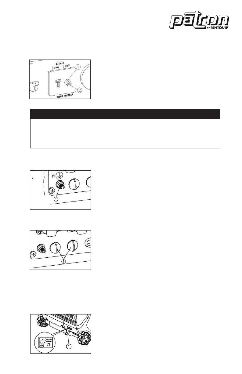
The DC protector turns to “OFF” automatically
when electric device being connected to the
generator is operating and current above the
rated flows. To use this equipment again, turn
on DC protector by pressing its button to “ON”.
1. “ON” Direct current is output.
2. “OFF” Direct current is not output.
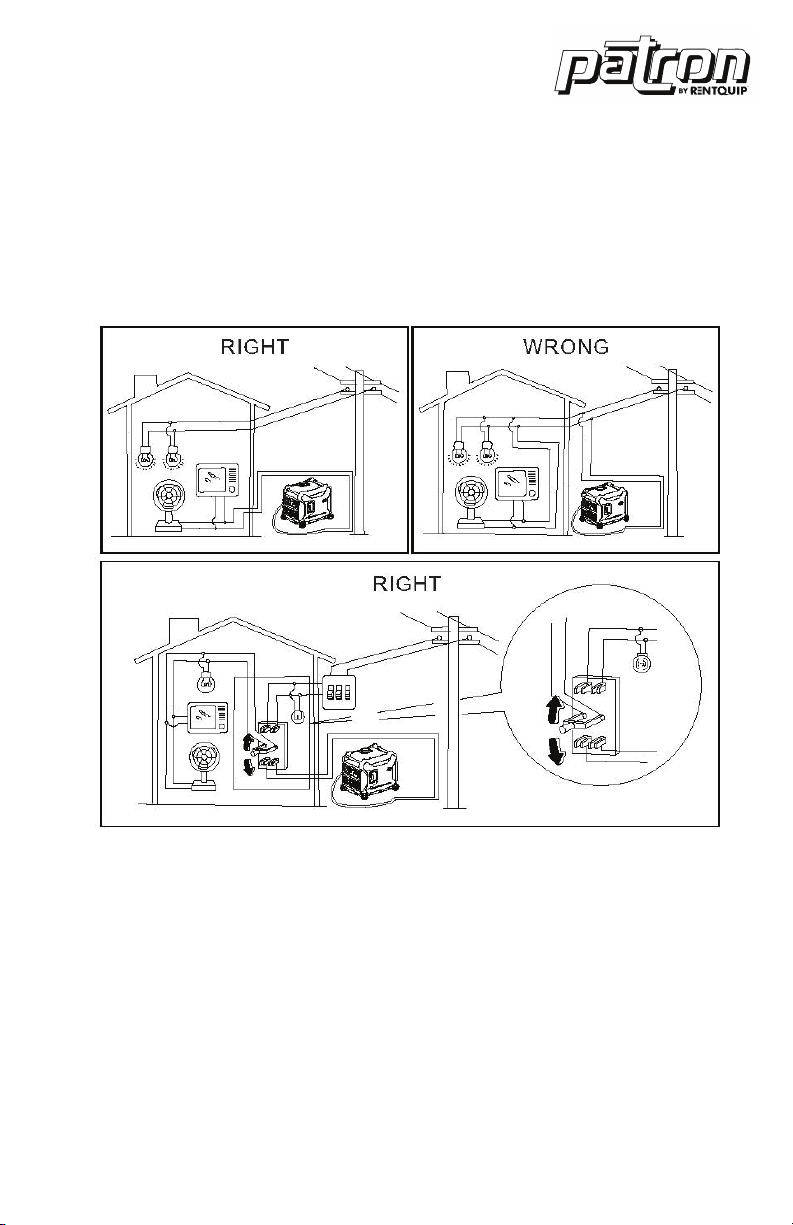
Ground (Earth) terminal (1) connects the earth
line for prevention of electric shock. When the
electric device is earthed, always the generator
must be earthed.
DC PROTECTOR
GROUND (EARTH) TERMINAL
NOTICE
• Reduce the load of the connected electric device below the speci-
fied rated output of the generator if the DC protector turns off. If the
DC protector turns off again, stop using the device immediately and
consult a franchised dealer.
This is the terminal for connecting special
cables for parallel running of two generator.
The parallel running requires two generator
and the special cables. (The rated output in
parallel running is 6.0Kva and the rated current
is 60A/100V;50A/120V;26A/230V.)
The handing, operation procedure and the
notes on usage are described in the PARALLEL
RUNNING KIT OWNER’S MANUAL included
in the Parallel.
During the operation and idle period of
machine, brake timely and switch to “STOP”.
In case of the machine is required to be moved,
switch the brake to “RUN”.
PARALLEL OPERATION OUTLETS
BRAKE

14
pre-operation
Make sure enough gasoline is in the fuel tank.
1. Fuel level gauge
Recommended fuel: Unleaded gasoline | Fuel tank capacity: Total: 10.0L
FUEL
Pre-Operation
NOTICE
• Pre-operation checks should be made each time operation.
WARNING
• The engine and muffler will be very hot after the engine has been run.
Avoid touching the engine and muffler while they are still hot with any
part of your body or clothing during inspection or repair.
WARNING
• Fuel is highly flammable and poisonous. Check “SAFETY
INFORMATION”(See page 2-5) carefully before filling.
• Do not overfill the fuel tank, otherwise it may overflow when the fuel
warms up and expands. After filling the fuel, make sure the fuel tank
cap is tightened securely.
• Immediately wipe off spilled fuel with a clean.
• Use only unleaded gasoline. The use of leaded gasoline
• Will cause severe damage to internal engine parts.

15
pre-operation
The generator has been shipped without
engine oil. Do not start the engine until filled
with the sufficient engine oil.
Do not tilt the generator when adding
engine oil. This could result in overfilling and
damage to the engine.
Recommended engine oil: SAE 10W -30
Recommended engine oil grade:
API Service SE type or higher
Engine oil quantity: 0.6 L
ENGINE OIL

16
operation
Before starting the engine, do not connect
any electric devices.
Turn the ESC switch to “OFF” (1)
Turn the 3 in 1 switch to “CHOKE”
a. Ignition circuit is switched on.
b. Fuel is switched on.
c. Choke is switched off.
TIP: The choke is not required to start a
warm engine. Push the choke knob in to the
position “ON”.
TIP:
• The generator can be used with the rated output load at standard
atmospheric conditions.
• “Standard atmospheric conditions ”; Ambient temperature 25.
• Barometric pressure 100kPa; Relative humidity 30%
• The output of the generator varies due to change temperature, altitude
(lower air pressure at higher altitude) and humidity.
• The output of the generator is reduced when the temperature, the
humidity and the altitude are higher than standard atmospheric
conditions.
• Additionally, the load must be reduced when using in confined areas, as
generator cooling is affected.
STARTING THE ENGINE
Operation
NOTICE
• Never operate the engine in a closed area or it may cause uncon-
sciousness and death within a short time. Operate the engine in a well
ventilated area. The generator has been shipped without engine oil.
Do not start the engine until filled with the sufficient engine oil.

17
operation
Electric Start
Turn the engine switch on the control panel
to ON Or press it to START if it is electrical
start state then generator unit can be
started In order to extend the service life
of the storage battery do not press on the
switch for more than 3 seconds and the
interval between two pressings should be
longer than 10 seconds.
Recoil Start
Grasp the carrying handle firmly to prevent
the generator from falling over when pulling
the recoil starter.
After the engine starts, warm up the engine
until the engine does not stop when the
choke knob is returned to the “ON” position.
(3)
TIP:
When starting the engine, with the ESC
“ON” and there is no load on the generator:
In ambient temperature below 0ºC (32ºF),
the engine will run at the rated (3600r/min)
for 5 minutes to warm up the engine.
In ambient temperature below 5ºC (41ºF),
the engine will run at the rated r/min (3600r/
min) for 3 minutes to warm up the engine.
The ESC unit operates normally after the
above time period, while the ESC is “ON”.
Release the load.
STOP THE ENGINE

18
operation
TIP: Turn off any electric devices.
1. Disconnect any electric devices.
2. Turn the ESC to “OFF” (1).
3. Turn the 3 in 1 switch to “OFF” (2).
a. Ignition circuit is switched off.
b. Fuel valve is switched off.
ALTERNATING CURRENT (AC) CONNECTION
NOTICE
• Be sure all electric devices including the lines and plug connections
are in good condition before connection to the generator.
• Be sure the total load is within generator rated output.
• Be sure the receptacle load current is within receptacle rated current.
WARNING
• Be sure any electric devices are turned off before plugging them in.
TIP: Make sure to ground (Earth) the generator. When the electric device
is earthed, always the generator must be earthed.
1. Start the engine.
2. Turn the ESC to “ON”.
3. Plug in to AC receptacle.
4. Make sure the AC pilot light is on.
5. Turn on any electric devices.
TIP: The ESC must be turned to “OFF” before increasing engine speed
to rated rpm.
• Most motorized appliances require more than their electrical rating for
startup. When an electrical motor is started, the overload indicator (red)
may come on. This is normal if the overload indicator (red) goes off
within 4 seconds. If the overload indicator (red) stays on, consult your
generator dealer.
• If the generator is connected to multiple loads or electricity consumers,
please remember to first connect the one with the highest starting
current. And last connect the one with the lowest starting current.

19
operation
• If the generator is overloaded, or if there is a short circuit in a connected
appliance, the overload indicator (red) will go ON. The overload
indicator (red) will stay ON, and after about 4 seconds, the connected
appliance(s) will shut off, and the output indicator (green) will go OFF.
Stop both engines and investigate the problem. Determine if the cause
is a short circuit in a connected appliance or an overload, correct the
problem and restart the generator.
BATTERY CHARGING
TIP:
• The generator DC rated voltage is 12V.
• Start the engine first, and then connect the generator to the battery for
charging.
• Before starting to charge the battery, make sure that the DC protector is
turned on.
1. Start the engine.
2. Connect the red battery charger lead to the positive (+) battery
terminal.
3. Connect the black battery charger lead to the negative (-) battery
terminal.
4. Turn the ESC “OFF” to start battery charging.
NOTICE
• Be sure the ESC is turned off while charging the battery.
• Be sure to connect the red battery charger lead to the positive (+)
battery terminal, and connect the black lead to the negative (-) battery
terminal. Do not reverse these positions.
• Connect the battery charger leads to the battery terminals securely
so that they are not disconnected due to engine vibration or other
disturbances.
• Charge the battery in the correct procedure by following instructions
in the owner’s manual for the battery.
• The DC protector turns off automatically if current goes above the
rated flow during battery charging. To restart charging the battery, turn
he DC protector on by pressing its button to “ON”. If the DC protec-
tor turns off again, stop charging the battery immediately and consult
a servicing dealer.

20
operation
AC PARALLEL OPERATION
TIP:
• Follow instructions in the owners manual for the battery to determine
the end of battery charging.
• Measure the specific gravity of electrolyte to determine if the battery is
fully charged. At full charge, the electrolyte specific gravity is between
1.26 and 1.28.
• It is advisable to check the specific gravity of the electrolyte at least
once every hour to prevent overcharging the battery.
Before connection an appliance to either generator, make sure that it is in
good working order and that its electrical rating does not exceed that of
the receptacle.
During parallel operation, the ESC switch should be in the same position
on both generators.
1. Connect the parallel operation cable between the generator to either
the main generator or companion generator following the instructions
supplied with the cable kit.
2. Start the engines and make sure the output indicator (green) on each
generator comes on.
3. Plug an appliance into the AC receptacle.
4. Turn on the appliance.
WARNING
• Never smoke or use broken connectors on the battery while charging.
Sparks may ignite the battery gas.
• Battery electrolyte is poisonous and dangerous, causing severe
burns, etc. contains sulfuric (sulphuric) acid. Avoid contact with skin,
eyes or clothing.
• Antidote:
EXTERNAL: Flush with water.
INTERNAL: Drink large quantities of water or milk. Follow with milk of
magnesia, beaten egg or vegetable oil . Call physician immediately.
EYES: Flush with water for 15 minutes and get prompt medical
attention.
• Batteries produce explosive gases. Keep sparks, flame, cigarettes,
etc., away. Ventilate when charging or using in closed space. Always
wear eye protection when working near batteries.
• Keep out of reach of children.

21
operation
AC PARALLEL OPERATION APPLICATIONS
TIP:
• Make sure that it is in good working order. A faulty appliance or power
cord can create a potential for electrical shock.
• If an appliance begins to operate abnormally, becomes sluggish, or
stops suddenly, turn it off immediately. Disconnect the appliance and
determine whether the problem is the appliance, or the rated load
capacity of the generator has been exceeded.
• Make sure that the combined electrical rating of the tools or appliance
does not exceed that of the generator.
• Never connect different generator models.
• Don’t remove the parallel operation cable when the generator operation.
• For single generator operation, the parallel operation cable must be
removed.
WARNING
• Substantial overloading that continuously lights the overload indicator
(red) may damage the generator Marginal overloading that temporarily
light the overload indicator (red) may shorten the service life of the
generator.
• For continuous operation, do not exceed the rated power.
• Rated power in parallel operation is: 6KW.

22
operation
APPLICATION RANGE
When using the generator, make sure the total load is within rated output
of a generator. Otherwise, generator damage may occur.
AC
Power
Factor 1 0.8-0.95 0.4-0.75
(Efficiency
0.85)
GI-3500 ~3,000W ~2,400W ~1,200W Rated
voltage 12V
Rated
current 8A
TIP:
• Application wattage indicates when each device is used by itself.
• The simultaneous usage of AC and DC power is possible but total
wattage should not exceed the rated output.
EX:
Generator rated output 3,000V A
Frequency Power factor
AC 1.0 ~3,000W
0.8 ~2,400W
DC --- 96W (12V/8A)

23
operation
NOTICE
• Do not overload. The total load of all electrical appliances must not
exceed the supply range of the generator. Overloading will damage
the generator.
• When supplying precision equipment, electronic controllers, PCs,
electronic computers, microcomputer based equipment or battery
chargers, keep the generator a sufficient distance away to prevent
electrical interference from the engine. Also ensure that electrical
noise from the engine does not interfere with any other electrical
devices located near the generator.
• If the generator is to supply medical equipment, advice should first be
obtained from the manufacturer, a medical professional or hospital.
• Some electrical appliances or general-purpose electric motors have
high starting currents, and cannot therefore be used, even if they lie
within the supply ranges given in the above table. Consult the equip-
ment manufacturer for further advice.
Table of contents
Other Rentquip Portable Generator manuals