Staubli PV-KBT4-EVO ST Series User manual

1/12
PV-KBT4-EVO ST PV-KST4-EVO ST
PV-SVK4
32.0717
PV-BVK4
32.0716
Verschlusskappen/Sealing caps
MA297 (de_en)
Montageanleitung
MA297 (de_en)
Assembly instructions
PV-Kupplungsbuchse PV-KBT4-EVO ST/...
PV-Kupplungsstecker PV-KST4-EVO ST/...
MC4-Evo stor
PV female coupler PV-KBT4-EVO ST/...
PV male coupler PV-KST4-EVO ST/...
MC4-Evo stor
Inhalt
Sicherheitshinweise ���������������������������������������������������������������������2
Erforderliches Werkzeug ��������������������������������������������������������������3
Vorbereitung der Leitung��������������������������������������������������������������4
Leitfaden zur Konfiguration der Steckverbinder ����������������������������4
Crimpen ��������������������������������������������������������������������������������������6
Montageprüfung��������������������������������������������������������������������������7
Stecken und Trennen�������������������������������������������������������������������8
Hinweise zur Installation���������������������������������������������������������������9
Technische Daten ����������������������������������������������������������������������10
Notizen������������������������������������������������������������������������������11 – 12
Content
Safety Instructions �����������������������������������������������������������������������2
Tools required������������������������������������������������������������������������������3
Cable preparation ������������������������������������������������������������������������4
Guideline for configuring the connectors��������������������������������������4
Crimping��������������������������������������������������������������������������������������6
Assembly check ��������������������������������������������������������������������������7
Mating and disconnecting������������������������������������������������������������8
Notes on installation ��������������������������������������������������������������������9
Technical Data ���������������������������������������������������������������������������10
Notes ��������������������������������������������������������������������������������11 – 12
2/12
Sicherheitshinweise Safety instructions
Bedeutung der Montageanleitung
Wenn die Montageanleitung und die folgenden Sicherheitshinweise
NICHT befolgt werden, können Lebensgefahr durch Stromschlag,
Lichtbögen, Brand oder ein Ausfall des Systems die Folge sein�
•Montageanleitung vollständig befolgen�
•Das Produkt nur entsprechend dieser Montageanleitung und
der technischen Daten anschließen und verwenden�
•Montageanleitung aufbewahren und an nachfolgende Verwen-
der weitergeben�
Importance of the assembly instructions
NOT following the assembly and safety instructions could result
in life-threatening injuries due to electric shock, electric arcs, fire,
or failure of the system�
•Follow the entire assembly instructions�
•Use and install the product only according to this assembly
instructions and the technical data�
•Safely store the assembly instructions and pass them on to
subsequent users�
Bestimmungsgemäße Verwendung
Der MC4-Evo stor Steckverbinder verbindet elektrisch den Inver-
ter und das BESS (battery energy storage system) im Gleich-
stromkreis�
Die Verwendung des Steckverbinders für andere Zwecke als in
einem Photovoltaik-System ist möglich, z� B� als Niederspan-
nungs-Gleichstrom-Komponente�
Dabei können andere Anforderungen und Spezifikationen als in
diesem Dokument beschrieben anwendbar werden�
•Für mehr Informationen Stäubli kontaktieren
www�staubli�com/electrical
Intended use
The MC4-Evo stor connector electrically connects the DC side of
an inverter and the BESS (battery energy storage system)�
The connector can be used for purposes other than those in
a photovoltaic array, e�g�, as a LVDC component� If the com-
ponent is used for other purposes, then the requirements and
specifications may be dierent from the ones described in this
document�
•For more information, contact Stäubli
www�staubli�com/electrical
Anforderungen an das Personal
Die Montage und Installation dürfen ausschließlich von einer
Elektrofachkraft oder einer elektrotechnisch unterwiesenen Per-
son durchgeführt werden�
•Eine Elektrofachkraft ist eine Person mit geeigneter fachlicher
Ausbildung, Kenntnissen und Erfahrungen, sodass sie Ge-
fahren erkennen und vermeiden kann, die von der Elektrizität
ausgehen können� Die Elektrofachkraft ist befähigt, geeignete
Schutzausrüstungen zu wählen und zu verwenden�
•Eine elektrotechnisch unterwiesene Person ist eine Person,
die durch eine Elektrofachkraft unterwiesen oder beaufsichtigt
wird, sodass sie Gefahren erkennen und vermeiden kann, die
von der Elektrizität ausgehen können�
Requirements for personnel
Only an electrician or electrically instructed person may assem-
ble, install, and commission the system�
•An electrician is a person with appropriate professional
training, knowledge, and experience to identify and avoid the
dangers that may originate from electricity� An electrician is
able to choose and use suitable personal protective equip-
ment�
•An electrically instructed person is a person who is instructed
or supervised by an electrician and can identify and avoid the
dangers that may originate from electricity�
Voraussetzungen für die Installation und Montage
•NIEMALS oensichtlich beschädigte Steckverbinder verwenden�
•NUR von Stäubli zugelassene Werkzeuge und Hilfsmittel
verwenden�
•NUR PV-Leitungen, die für die Steckverbinder zugelassen
sind, an die Steckverbinder anschließen�
Prerequisites for installation and assembly
•NEVER use an obviously damaged product�
•ONLY tools and procedures approved by Stäubli shall be
used�
•ONLY approved PV-cables shall be assembled to the connec-
tor�
Sichere Montage und Installation
Aktive Teile können auch nach Freischalten der Photovoltaik-
Anlage und Trennen der Steckverbinder unter Spannung stehen�
•Den Steckverbinder NUR im spannungsfreien Zustand des
Photovoltaik-Strings oder -Bereiches montieren�
Safe assembly and mounting
Live parts can remain energized after isolation or disconnection
•ONLY Install the product when the photovoltaic-array or -string
is de-energized�
Stecken und Trennen
•IMMER vor dem Trennen und Stecken der Steckverbinder
Photovoltaik-Anlage lastfrei schalten�
•NIEMALS den Steckverbinder unter Last trennen�
•NIEMALS Stecker oder Buchse des Stäubli-Steckverbinders
mit Buchse bzw� Stecker eines anderen Herstellers verbinden�
Mating and disconnecting
•ALWAYS de-energize the photovoltaic system before mating
and disconnecting the connectors�
•NEVER disconnect the connectors under load�
•NEVER connect male or female part of Stäubli connector with
connectors of other manufacturers�
Komponente NICHT ändern oder reparieren
•Steckverbinder nur einmal montieren�
•Steckverbinder nach der Montage NICHT nachträglich modi-
fizieren�
•Defekte Steckverbinder austauschen�
Do NOT modify NOR repair component
•Mount connector only once�
•Do NOT modify connectors after assembly�
•Replace defective connectors�

3/12
1
2
5
3
4
6
Erforderliches Werkzeug Tools required
(ill. 1)
Abisolierzange PV-AZM… inklusive
eingebauten Abisoliermessern sowie
Sechskantschlüssel SW 2,5�
(ill. 1)
Stripping pliers PV-AZM��� including
built-in stripping blades and Allen key
2�5 mm�
Hinweis:
Bedienungsanleitung MA267,
www�staubli�com/electrical
Note:
Operating instructions MA267,
www�staubli�com/electrical
(ill. 2)
Crimpzange PV-CZM��� und Lokator�
Crimpbereich
Crimping range
Crimpzange
Crimping pliers
Lokator
Locator
2.5/4/6mm²
(14/12/10AWG)
PV-CZM-61100
32.6020-61100
PV-LOC-MC4-EVO 2
32.6084
4/10/6mm2
(12/8/10AWG)
PV-CZM-60100
32.6020-60100
PV-LOC-MC4-EVO 2
32.6083
(ill. 2)
Crimping pliers PV-CZM��� and locator�
Hinweis:
Bedienungsanleitung MA704,
www�staubli�com/electrical
Note:
Operating instructions MA704,
www�staubli�com/electrical
(ill. 3)
Montage- und Entriegelungswerkzeug
PV-MS-PLS, Bestell�-Nr� 32�6058
(ill. 3)
Assembly and unlocking tool
PV-MS-PLS, Order No� 32�6058
Hinweis:
Bedienungsanleitung MA270,
www�staubli�com/electrical
Note:
Operating instructions MA270,
www�staubli�com/electrical
(ill. 4)
PV-WZ-Torque-Set,
Bestell-Nr� 32�0065
oder
Drehmomentschlüssel SW17
(ill. 4)
PV-WZ-Torque-Set,
Order No� 32�0065
or
Torque wrench 17 mm
(ill. 5)
Prüfstift PV-EVO-PST,
Bestell-Nr� 32�6073
(ill. 5)
Test plug PV-EVO-PST,
Order No� 32�6073
(ill. 6)
Kabelschere PV-WZ-KS,
Bestell-Nr� 32�6080
(ill. 6)
Cable cutter PV-WZ-KS,
Order No� 32�6080
Hinweis:
Bedienungsanleitung MA705,
www�staubli�com/electrical
Note:
Operating instructions MA705,
www�staubli�com/electrical
Leiterquerschnitt
Conductor cross section
Typ
Type
Bestell-Nr.
Order no.
1.5/2.5/4/6mm²
(14/12/10AWG) PV-AZM-156 32.6027-156
4/6/10mm²
(12/10/8AWG PV-AZM-410 32.6027-410

4/12
7
Vorbereitung der Leitung Cable reparation
(ill. 7)
Es müssen Anschlussleitungen mit
einem flexiblen Litzenaufbau der Klas-
sen 5 und 6 angeschlossen werden�
Ausschließlich verzinnte Kupferleitungen
verwenden�
(ill. 7)
Cables with a strand class 5 and 6
shall be connected� Use tinned copper
cables only�
Achtung
Keine oxidierten oder blanken
Leitungen verwenden� Alle Stäubli
Solarleitungen verfügen über einen
hochwertigen verzinnten Leiter�
Aus Sicherheitsgründen untersagt
Stäubli die Verwendung von PVC-
Leitungen sowie den Einsatz von
unverzinnten Leitungen vom Typ
H07RN-F�
Attention
Do not use oxidized nor bare (i�e�
uncoated) conductors� All Stäubli
solar cables have high grade tinned
conductors� For safety reasons,
Stäubli prohibits the use of PVC
cables and the use of non-tinned
cables of type H07RN-F�
Maße A und b gemäß ill� 6 und Tab� 1 und 2 kontrollieren�
Korrekte Auswahl der passenden Konfiguration:
Check dimensions A and b in accordance with ill� 6 and Tab� 1
and 2� Proper selection of the appropriate configuration:
Hinweis:
Die verwendbaren Dichtungen sind durch Farben leicht zu
unterscheiden:
Note:
The usable seals can be easily distinguished by the color:
DI Rotbraun
DX Gelb
DII Grau
DI Maroon
DX Yellow
DII Grey
Leitfaden zur Konfiguration der Steckverbinder Guideline for configuring the connectors
Hinweis:
Liegt der verwendete Kabeldurchmesser zwischen zwei
Grenzen, verwenden Sie bitte den kleineren Dichteinsatz�
Note:
Please use the smaller sealing if the cable diameter used is
between two limits�
1. MC4-Evo ST Produktkonfiguration in Kombination mit
TUV Rheinland, TUV Rheinland/UL und cTUVus
Bei Verwendung von TÜV Rheinland, TÜV Rheinland/UL (dual),
oder cTÜVus zertifizierten Leitungen1),2) passende Konfiguration
anhand Tab� 1 auswählen:
1. MC4-Evo ST product configuration in combination with
TUV Rheinland, TUV Rheinland/UL and cTUVus
Choose the suitable configuration in Tab� 1 by using TÜV
Rheinland, TÜV Rheinland/UL (dual) or cTÜVus certified
cables1),2):
1) An den Stecker angeschlossene Leitungen müssen für die Verwendung in pho-
tovol-taischen Systemen geeignet sein und den Anforderungen von IEC 62930
entsprechen�
2) Für eine Anwendung des Produkts in Systemen > DC 1000 V, müssen bei der Aus-
wahl der PV Leitung folgende Punkte berücksichtigt werden:
- Die PV-Leitung muss Leiterklasse 5 nach IEC 60228:2005 erfüllen
- Das Mantelmaterial der PV-Leitung muss Isolierstoklasse 1 nach IEC 60664-1
erfüllen�
1) Cables connected to the connector shall be suitable for use in photovoltaic sys-
tems and shall comply with the requirements of IEC 62390�
2) For an end use of the product in systems > DC 1000 V, the following points must
be considered when selecting the PV cable:
- The PV cable has to meet conductor class 5 according to IEC 60228:2005
- The sheath material of the PV cable has to meet insulation class 1 according to
IEC 60664-1�
Leitungsquerschnitt
Conductor cross section
b: Kontrollmaß
b: control measure Typ
Type
mm2AWG mm
1.5 – 2.5 14 ~ 4 PV-K..T4-EVO ST/2.5I PV-K..T4-EVO ST/2.5X PV-K..T4-EVO ST/2.5II
4 – 6 12/10 ~ 5.8 PV-K..T4-EVO ST/6I PV-K..T4-EVO ST/6X PV-K..T4-EVO ST/6II
10 8 ~ 6.5 - PV-K..T4-EVO ST/10X PV-K..T4-EVO ST/10II
Ø-Bereich der Leitung (mm)
Ø-range of the cable (mm)
4.7 – 6.4 5.9 – 7.3 6.4 – 8.4
Verwendbarer Dichteinsatz
Usable seals
DI
Rotbraun/Maroon
DX
Gelb/Yellow
DII
Grau/Grey
Tab. 1
ill. 6

5/12
8
2. MC4-Evo ST Produktkonfiguration in Kombination mit UL
Bei Verwendung von ausschließlich UL-zertifizierten Leitungen
passende Konfiguration anhand Tab� 2 auswählen:
2. MC4-Evo ST Product configuration in combination with UL
Select the suitable configuration in Tab� 2 by using UL certified
cables only:
b: Kontrollmaß
b: control
measure
Leitungsquerschnitt
Conductor cross section
A: Ø-Bereich der Leitung (mm)
A: Ø-range of the cable (mm)
Kabeltyp
Cable type
TYLZ (USE-2) bis/up to DC 600 V
ZKLA (PV-wire) bis/up to DC 1000 V 4.93 – 6.5 6.5 – 8.5
ZKLA (PV-wire) bis/up to DC 2000 V 5.58 – 6.5 5.76 – 7.45 6.5 – 8.5
mm AWG (stranding) Typ/Type
~ 4 14
(19 – 49) PV-K...T4-EVO ST/2,5I PV-K...T4-EVO ST/2,5X PV-K...T4-EVO ST/2,5II
~ 5.8 12
(19 – 65)
10
(19 – 105) PV-K...T4-EVO ST/6I PV-K...T4-EVO ST/6X PV-K...T4-EVO ST/6II
~ 6.5 8
(19 – 168) PV-K...T4-EVO ST/10X PV-K...T4-EVO ST/10II
Verwendbarer Dichteinsatz/Usable seals DI
Rotbraun/Maroon
DX
Gelb/Yellow
DII
Grau/Grey
Tab. 2
(ill. 8)
Leitung auf Maß 6,0 bis 7,5mm abiso-
lieren�
(ill. 8)
Strip cable to dimension 6�0 to 7�5mm�
Achtung
Beim Abisolieren keine Einzeldrähte
abschneiden!
Attention
Do not cut individual strands when
stripping!

6/12
12
11
C
9
10
K
Crimpen Crimping
(ill. 9)
•Klemmbügel (K) önen und festhalten�
•Kontakt in den passenden Quer-
schnittsbereich einlegen�
•Crimplaschen (C) nach oben drehen�
•Klemmbügel (K) loslassen�
•Der Kontakt ist fixiert�
(ill. 9)
•Open clamp (K) and hold tight�
•Insert the contact in the appropriate
cross-section range�
•Turn the crimping flaps (C) upwards�
•Release clamp (K)�
•The contact is locked�
Hinweis:
Darauf achten, dass der Kontakt
in der Aufnahme liegt und durch den
Klemmbügel gehalten wird�
Note:
Make sure that the contact is
placed in the housing and is held by
the clamp�
(ill. 10)
Überprüfen dass die Crimplaschen noch
richtig ausgerichtet sind�
Die Zange leicht zusammendrücken, so
dass die Crimplaschen innerhalb des
Crimpeinsatzes liegen�
(ill. 10)
Verify if the crimping flaps are still cor-
rectly aligned�
Press the pliers gently together until
the crimping flaps are properly located
within the crimping die�
(ill. 11)
Abisolierte Leitung einführen, bis die
Litzen der Leitung am Klemmbügel
anschlagen�
Crimpzange ganz schließen�
(ill. 11)
Insert the stripped lead end until the
lead strands come up against the
locator�
Completely close the crimping pliers�
(ill 12)
Crimpung visuell kontrollieren be-
züglich der Kriterien, die in
IEC 60352-2 beschrieben sind�
(ill 12)
Visually check the crimp according to
the criteria written in IEC 60352-2�
Sicherstellen, dass:
•alle Litzen in der Crimphülse einge-
schlossen sind
•die Crimphülse nicht deformiert ist
und kein Teil der Crimplaschen fehlt
•die Crimpung symmetrisch ist
•auf der Kontaktseite der Crimpung ein
„Bündel“ Litzen sichtbar ist�
Confirm that:
•all of the strands have been captured
in the crimp sleeve
•the crimp sleeve is not deformed or
missing any portion of the crimp flaps
•that the crimp is symmetrical
•a “brush” of conductor strands are
visible on the contact side of crimp�

7/12
13
15
14
Montageprüfung Assembly check
(ill. 13)
Angecrimpten Kontakt von hinten in die
Isolation bis zum Einrasten einführen�
Es ertönt ein „Klick“-Geräusch, sobald
er vollständig eingefügt ist�
Durch leichtes Ziehen an der Leitung
prüfen, ob das Metallteil richtig einge-
rastet ist�
(ill. 13)
Insert the crimped-on contact into the
insulator of the male or female coupler
until engaged�
You will typically hear a “click” sound
once fully inserted�
Pull gently on the lead to check that the
metal part is correctly engaged�
(ill. 14)
Prüfstift mit der entsprechenden Seite in
die Buchse bzw� in den Stecker bis zum
Anschlag einstecken�
Bei richtig montiertem Kontakt muss
die weisse Markierung am Prüfstift noch
sichtbar sein�
(ill. 14)
Insert the appropriate end of the test pin
into the male or female coupler as far as
it will go�
If the contact is correctly located, the
white mark on the test pin must still be
visible�
(ill. 15)
•Leitungsverschraubung mit
PV-MS-PLS handfest anziehen�
•Leitungsverschraubung mit dem
PV-WZ-Torque-Set anziehen und mit
dem PV-MS-PLS den Steckverbinder
kontern�
(ill. 15)
•Pre-tighten cable gland with tool
PV-MS-PLS�
•Tighten cable gland using
PV-WZ-Torque-Set while supporting
the insulator front with the
PV-MS-PLS�
Hinweis:
Das wirksame Anzugsdrehmoment
muss auf die für die Anwendung
ausgewählte Solarleitung abgestimmt
werden�Siehe Tab� 3�
Note:
The acting tightening torque must
be adapted to the solar cables used
in each specific case�
See Tab 3�
Hinweis:
Stäubli empfiehlt den eingesetzten
Drehmomentschlüssel vor Montage-
beginn zu kalibrieren�
The NFPA National Electric Code
(NEC 2017) erfordert die Verwendung
eines kalibrierten Drehmoment-
schlüssels nach Abschnitt 110�14(D)�
Note:
Stäubli recommends to use a cali-
brated torque wrench for assembly�
The NFPA National Electric Code
(NEC 2017) requires the use of a
calibrated torque wrench per section
110�14(D)�
Leitungsdurchmesser
Cable diameters
Anzugsdrehmoment
Tightening torque
AWG mm2N m
14 2.5 4.5
12 4 4.0
10 6 3.5
8 10 4
Tab. 3
8/12
16
17
Stecken und Trennen Mating and disconnecting
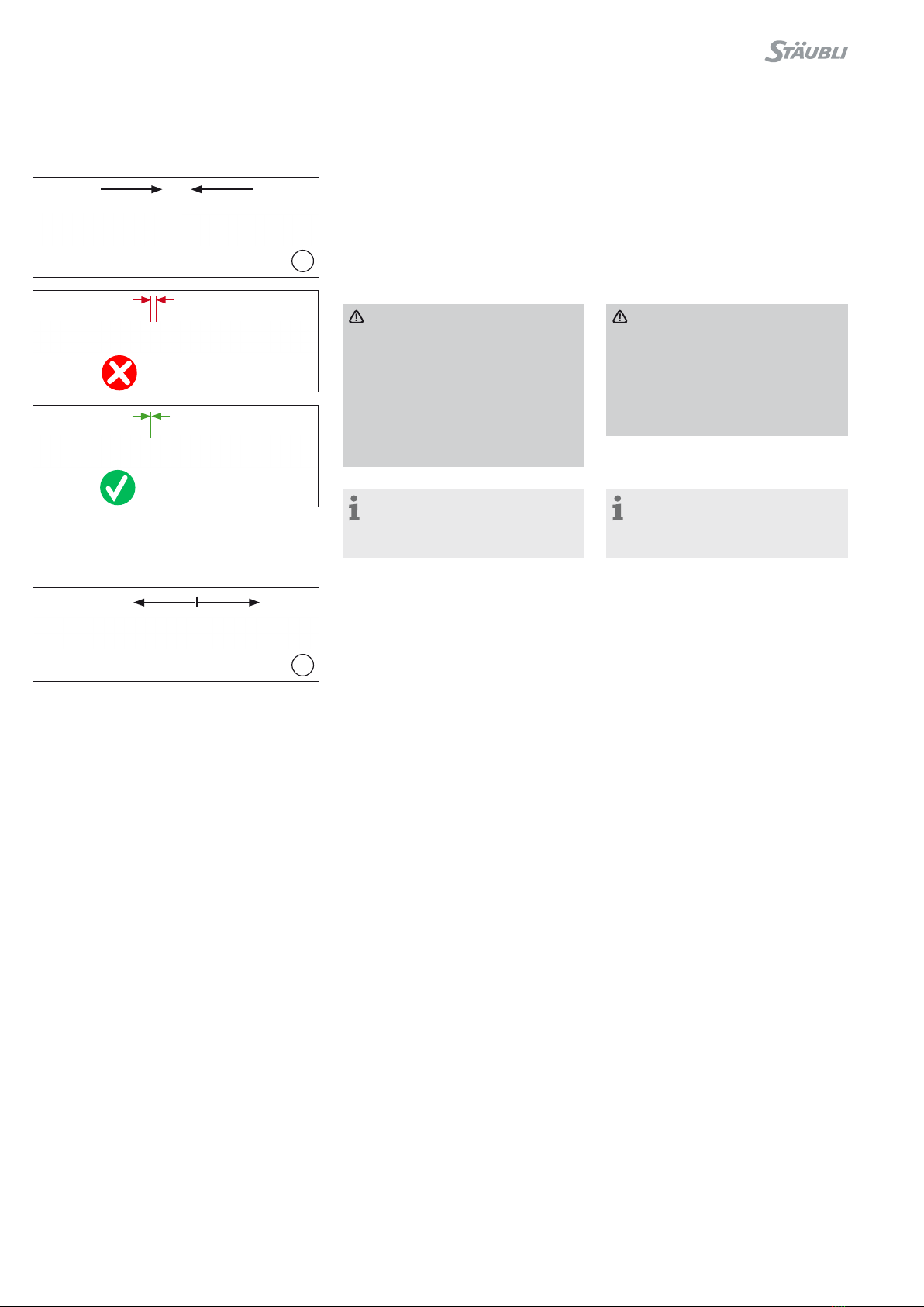
(ill. 16)
Stecken:
Leitungskupplungen zusammenstecken
bis ein „Klick“ hörbar ist� Korrektes
Einrasten durch Ziehen an der Leitungs-
kupplung kontrollieren (Zugkraft max�
20 N)�
(ill. 16)
Mating:
Mate the cable coupler until a „click“
can be heard� Check correct engage-
ment by lightly pulling on the connector
(maximum pulling force: 20 N)�
Achtung
Bei der Montage sind nicht voll-
ständig eingerastete Leitungskup-
plungen unzulässig, da dies zu
einer dauerhaften Verformung der
Rasthaken führen kann und damit
zum Verlust der Verriegelungsfunk-
tion�
Die korrekte Montage ist in jedem
Fall zu überprüfen�
Attention
Assembly of not fully engaged
connectors is not permitted as this
could lead to a permanent deflec-
tion of clips and thus to a potential
loss of the locking function�
The correct assembly has to be
verified at all times�
Hinweis:
Ungesteckte Steckverbinder müs-
sen mit Stäubli Verschlusskappen vor
Verunreinigungen geschützt werden�
Note:
Unmated connectors must be pro-
tected from any contamination using
Stäubli sealing caps�
(ill. 17)
Trennen:
Zum Entriegeln PV-MS-PLS/2 verwen-
den�
(ill. 17)
Disconnecting:
Use PV-MS-PLS/2 to disconnect�

9/12
Hinweise zur Installation Notes on installation
Allgemeine Installationshinweise
•Nicht gesteckte Steckverbinder sind mit Verschlusskappen
(Buchse PV-BVK4, Bestell-Nr� 32�0716; Stecker PV-SVK4,
Bestell-Nr� 32�0717) vor Umwelteinflüssen zu schützen (Feuch-
tigkeit, Schmutz, Staub etc�)�
•Kontaminierte Steckverbinder nicht miteinander verbinden�
•Steckverbinder dürfen nicht in Berührung mit jeglichen Chemi-
kalien kommen�
•Die Auslegung der Kurzschlussfestigkeit des gesamten Sys-
tems darf die Kurzschlussfestigkeit des Steckverbinders nicht
überschreiten�
Kurzschlussfestigkeit der Stecker ist mit Stäubli abzuklären�
General notes on installation
•Unmated connectors must be protected from environmental
impact (moisture, dirt, dust, etc�) with sealing caps (socket
PV-BVK4, order No� 32�0716; plug PV-SVK4, order No�
32�0717)�
•Do not mate contaminated connectors�
•Connectors must not come into contact with any chemicals�
•The design of the short-circuit resistance of the entire system
must not exceed the short-circuit resistance of the connector�
Short-circuit resistance of connectors to be clarified with
Stäubli�
Leitungsführung
Die Leitung muss so installiert werden, dass sie mindestens 20 mm
gerade und ohne Biegung oder Belastung aus der Verschraubung
bzw� den Dichtungen des Steckverbinders herausgeführt wird�
Spezifikationen des Leitungsherstellers zum Biegeradius beach-
ten�
Cable routing
Cable management must allow a minimum of 20 mm of cable
that exits straight from the cable seal without bending or stress�
Refer to cable manufacturer specification for minimum bending
radius�
Verunreinigte/beschädigte Steckverbinder:
•Sicherstellen, dass der Steckverbinder nicht durch Umwelt-
einflüsse verunreinigt wird (z� B� durch Erde, Wasser, Insekten,
Staub)�
•Sicherstellen, dass die Oberfläche des Steckverbinders nicht
verunreinigt wird (z� B� durch Aufkleber, Farbe, Schrumpf-
schläuche)�
•Der Steckverbinder darf nicht direkt auf der Dachfläche liegen�
•Sicherstellen, dass der Steckverbinder sich nicht an der tiefsten
Stelle der Verkabelung befindet, wo sich Wasser ansammeln
kann�
•Sicherstellen, dass der Steckverbinder nicht in stehendem Was-
ser zu liegen kommt�
•Sicherstellen, dass die Kabelbinder nicht direkt am Steckerver-
bindergehäuse befestigt werden�
Contaminated/damaged connectors:
•Do not allow connectors to be contaminated by the environ-
ment (e�g� soil, water, insects, dust)�
•Do not allow the connector to be contaminated on its surface
(e�g� stickers, paint, heat shrink tubing)�
•Do not allow that the connector is directly on the roofing sur-
face�
•Do not allow that the connector is at the lowest point of cabling
where water can collect�
•Do not allow that the connector is in standing water�
•Do not allow cable ties to be mounted directly on the connector
body�
Mechanische Beanspruchung:
•Sicherstellen, dass die Steckverbinder keiner dauerhaften me-
chanischen Zugbelastung oder Vibration ausgesetzt sind�
•Die Steckverbinder sollen nicht durch das Leitungsmanagement
belastet werden�
Mechanical stress:
•Check that the connectors are not subjected to a permanent
mechanical tensile load or vibration�
•Connectors shall not be under strain from cable management�
Min.
20 mm

10/12
Typenbezeichnung Type designation PV-KST4-EVO ST/xy
PV-KBT4-EVO ST/xy
Steckverbindersystem Connector system Ø 4 mm
Bemessungsspannung Rated voltage DC 1500 V (IEC 62852:2014+Amd.1:2020)
DC 1500 V (UL 6703)
Bemessungsstrom (IEC) Rated current (IEC)
32 A (2.5 mm²)
42 A (4.0 mm²)
47 A (6.0 mm²)
62 A (10.0 mm²)
Bemessungsstrom (UL) Rated current (UL)
30 A (14 AWG)
39 A (12 AWG)
50 A (10 AWG)
70 A (8 AWG)
Bemessungsstossspannung Rated impulse voltage 16 kV (DC 1500 V)
Umgebungstemperaturbereich Ambient temperature range -40°C ... +85°C (IEC/UL)
Obere Grenztemperatur Upper limiting temperature 115°C (IEC)
Schutzart, gesteckt Degree of protection, mated IP65/IP68 (1 m, 1 h)
Schutzart, ungesteckt Degree of protection, unmated IP2x
Überspannungskatekorie/Verschmutzungsgrad Overvoltage category/Pollution degree CAT III/3
Kontaktwiderstand der Steckverbinder Contact resistance of plug connectors < 0.2 mΩ
Polarität der Steckverbinder Polarity of connectors Buchse/Socket = Plus/positive
Stecker/Plug = Minus/negative
Verriegelungssystem Locking system Locking type
Schutzklasse (IEC) Safety class (IEC) II
Kontaktsystem Contact system MULTILAM
Anschlussart Type of termination Crimpen/crimping
Hinweis Warning Nicht unter Last trennen
Do not disconnect under load
Kontaktmaterial Contact material Kupfer verzinnt, copper, tin plated
Isolationsmaterial Insulation material PA
Flammklasse Flame class UL94-V0
Steckkompatibel mit Compatible with MC4-Evo stor
(PV-ADB4-EVO ST/x, PV-ADS4-EVO ST/x)
TÜV-Rheinland zertifiziert nach
IEC 62852:2014+Amd.1:2020
TÜV-Rheinland certified according to
IEC 62852:2014+Amd.1:2020 R 60163331
UL zertifiziert nach UL 6703 UL certified according to UL 6703 E343181
Technische Daten Technical Data

11/12
Notizen/Notes:

12/12
Hersteller/Manufacturer:
Stäubli Electrical Connectors AG
Stockbrunnenrain 8
4123 Allschwil/Switzerland
Tel. +41 61 306 55 55
Fax +41 61 306 55 56
www.staubli.com/electrical
© by Stäubli Electrical Connectors AG, Switzerland – MA297 – 09.2022, index a Marketing Communications – Änderungen vorbehalten / Subject to alterations
Notizen/Notes:
Other manuals for PV-KBT4-EVO ST Series
1
This manual suits for next models
6
Table of contents
Other Staubli Adapter manuals


