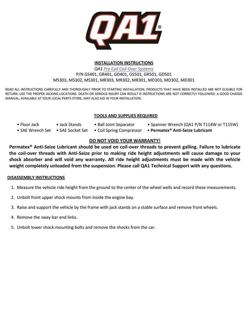
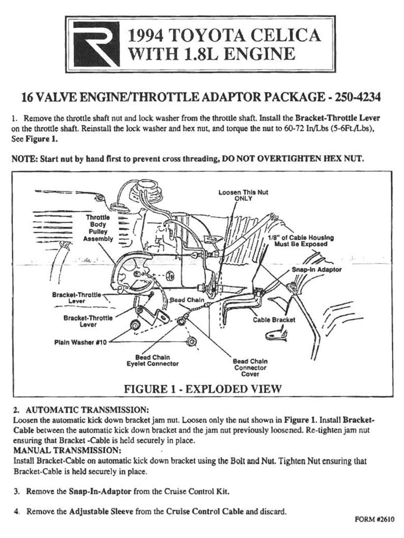
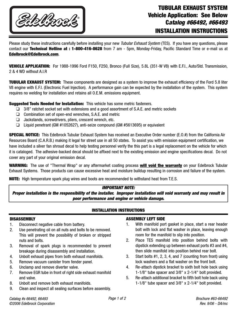
Stealth International WSMG1 User manual

MANUAL
TRANSMISSION
Service
."anual
~L.
.,
••
1.'1
•••
Dodg_
St_lth
A/T
Turbo
,.aCk1saa
M~.ublehl
IIIIrTl
00
TlNIn
Turbo
.,_1.'1
__
Mlt.ubi.hl
30QOElT
VA4

WSMG1,W6MG1
MANUAL
TRANSMISSION
Preface
This book was translated from the original
Japanese language service manual published
by Mitsubishi Motors Corporation ofJapan.
Translation was performed by volunteers from
3000GT/Stealth International, an owners and
enthusiast group focused
on
the Mitsubishi
3000GT, Dodge Stealth and Mitsubishi GTO.
Great care has been taken to ensure the
accuracy
of
the information contained
in
this
manual, but errors may still be possible due
to the nature ofthe translation. Therefore,
this manual is presented as a guide only,
and repair procedures should not
be
undertaken by unskilled individuals who do
not posess a thorough understanding
of
the
subject material.
The authors ofthis manual will not be held
responsible for any personal injury or damage
to property incurred while performing the
procedures described within.
All tasks
in
this manual are undertaken at your
own risk.
Group
Index
c::lut;ct1
..................................
~
Manaul
Transmission
.......
~
Transfer
C::ase
Recall
.......
E33
Applicable
Models
This book covers the Getrag W5MG1 and
W6MG1 all-wheel drive manual transaxles
found
in
the following models:
1991 -1996 Dodge Stealth RlT Turbo
1991 -1999 Mitsubishi 3000GT VR4
1990 -1999 Mitsubishi GTO Twin Turbo
This book would not be possible without the
contributions
of
the following people:
Translation, and layout
JeffVanOrsdal
Additional Translation
Frank Chen, Kotaru Yamaguchi,
Corumisri
Technical Assistance
Bret Brinkmann
Jeff Lucius
Financial assistance
Many generous members of 3000GT I Stealth
International
Visit 3000GT I Stealth International on the web at www.3si.org

Introduction
Introduction
Scope
of
this
manual
This book explains the main service points
regarding the transmission itself. However,
please utilize the relevant service manual
for the car model and year
in
question
when concerns arise regarding onboard
inspection and service.
Important
points
(1) Component diagrams are published
at the beginning of each section so that
you may more easily visualize the
assembled state
of
the component or
su
b-assembly.
(2) Numbered service procedures are
displayed
in
the component diagrams
along with indications
of
non-reusable
parts and torque specifications.
(3) Main service points and maintenance
points are explained
in
detail, along with
usage and descriptions
of
special tools.
About
inspection
Descriptions are provided for procedures
to
be
taken when defective or damaged
parts are discovered during inspection.
Symbols for lubricants, sealants and adhesives
Information concerning the locations of lubricarion
and for application
of
sealants and adhesives
is
provided, by using symbols,
in
the diagram
of
component parts or
on
the page following the
component parts page.
4IiN
.................
Grease (multipurpose unless there
is
a brand or type specifed)
t
................
Brake fluid or automatic transmission
fluid
.....
.....
..
.........
..
.........
..
...........Sealant or adhesive
r,.
.............................................................
Gear oil
Removal procedures
The part designation number corresponds to the
number
in
the illustration to indicate removal
procedures.
Disassembly procedures
The part designation number corresponds to the
number
in
the illustration to indicate disassembly
procedures.
Installation procedures
Specified
in
case installation
is
impossible
in
reverse order of removal procedures. Omitted if
installation
is
possible
in
reverse order
of
removal
procedures
Reassembly procedures
Specified
in
case reassembly
is
impossible
in
reverse order of disassembly procedures. Omitted
if reassembly is possible
in
reverse order of
disassembly procedures.
Classification of major maintenance or service
points
(JAQ
: Indicates that there are essential points for
removal or disassembly.
.A,
: Indicates that there are essential points for
installation or reassembly.
I--
,-----
l-
f---
r--
-
f---

Group number and page number
21
- B
Disassembly
/
Reassembly
Introduction
Group title
~
Section title
Clutch
-
Clutch
Release
Cylinder
Torque specification 2
Jia
6 6 1
Denotes non-
reusable part
Coat
all
internal
parts
in
brake
fluid
before
reassembly
Disassembly
Procedure
1.
Pushrod
2.
Boot
(:lAO_A. 3.
Piston
cup
(:lAO_A. 4.
Piston
5.
Conical
spring
6.
Cap
7.
Bleeder
screw
8. Release
cylinder
Disassembly
service
points
(JAc')
Removal
of
piston
cup
/
piston
TFM0494
(1) Remove the corrosion from the piston-removal port
of
the release cylinder.
(2) Remove the piston from the release cylinder using
compressed air.
Caution
1.
Cover
with
rags
to
prevent
the
piston
from
6CL035
popping
out.
~------------------------~
2.
Apply
compressed
air
slowly
to
prevent
brake
fluid
from
splashing.

21
CLUTCH
Maintenance
Standards
............................................
21-2
Torque
Specifications
................................................
21-2
Lu
brication
....................................................................
21-2
Special
Tools
.................................................................
21-3
Clutch
Assembly
..........................................................
21-4
Clutch
Release
Cylinder
.............................................
21-8
Clutch
Damper
............................................................
21-10

21
- 2
Clutch
-
Standards,
Torque
and
Lubrication
Maintenance
Standards
Item Limit Value mm
Clutch disk facing rivet sink Below 0.3
Diaphragm spring end height difference Within 0.5
Opening of release cylinder bore and piston major diameter Above 0.15
Torque
Specifications
Item Torque
Clutch damper bracket attachment bolt 6.5 tUbs / 9 Nm
Clutch damper installation bolt 14 fUbs / 19 N.m
Clutch oil tube filling nut
11
ftlbs
/15
Nm
Release fork fulcrum 26
ftlbs
/ 36 Nm
Clutch oil line bracket attachment bolt 14 tUbs / 19 N.m
3-way type connector mounting bolt 14 tUbs / 19 N.m
Clutch release cylinder mounting bolt 14 tUbs / 19 N.m
Union bolt
17
ft.lbs / 23 Nm
Clutch cover installation bolt 14
ftlbs
/ 19 N.m
Clutch release cylinder air breather 8 fUbs /11 Nm
Clutch damper air breather 6.5 ft.lbs / 9 Nm
Lubricants
Item Specified lubricant
Clutch release bearing sleeve diameter
Clutch release bearing and shift fork contact section Molykote
TA
#2
Shift fork and fulcrum contact section
Clutch release cyliner pushrod tip
Inside splines
of
clutch disk Molykote TA
#1
or #2
Clutch release cylinder piston and piston cup SAE J1703 (DOT3)
Clutch damper O-ring

Clutch
-
Special
Tool
Tool
Part Number
MD998126
Name
Clutch disk
centering guide
21
- 3
Use
Positioning the clutch disk

21
- 4
Removal/
Installation
18
4IiM
Removal
Procedure
27
fUbs
36Nm
22
4IiM
20
17
4IiM
1.
Clutch
cylinder
release
tube
2.
Clutch
cylinder
release
tube
3.
Clutch
cylinder
release
tube
4.
Clip
5.
Bracket
6.
Clutch
damper
7.
3-way
junction
block
8.
Insulator
9.
Bracket
10.
Insulator
11.
Banjo
bolt
12.
Crush
washer
23
19
c?4iM
Clutch
-
Clutch
Assembly
14
ft.lbs
19
Nm
4 5
~
~~
1
~
fI-~o
6
3---{
2
11
ft.lbs
y-----,
15
Nm
--7
14
fUbs
19
Nm
~
13
~
16
rf
~
¥
@--10
15
1~
1/
11
ft.lbs
115
Nm
1D12
117
ft.lbs
11
23 Nm
13.
Union
14. Release
cylinder
valve
15. Release
cylinder
spring
"0'
16.
Clutch
release
cylinder
..
C.
17.
Clutch
cover
..
C.
18.
Clutch
disk
ClAo
..
a;
19.
Clutch
release
fork
..
U 20.
Throw-out
bearing
21.
Boot
22. Release
fork
fulcrum
23.
Clutch
housing

Clutch
-
Clutch
Assembly
21
- 5
Fulcrum
Release
fork
Clip
Removal
service
points
oAQ
Release
fork
removal
(1
)Slide release fork
in
direction
of
arrow and disengage
fulcrum from clip to remove release fork.
Be
careful not to
cause damage to clip by pushing release fork
in
the direction
other than that
of
arrow and removing it with force.
L----
___________
D_C_LO-----'02
Inspection
Rivet sink
~~ifk~
6CL003
Clutch
cover
assembly
(1
)Check the diaphragm spring end for wear and uneven
height. Replace
if
wear is evident or height difference
exceeds the limit.
Limit:
0.5
mm
(.020 in.)
(2)Check the pressure plate surface for wear, cracks and
seizure.
(3)Check the strap plate rivets for looseness and replace
the clutch cover assembly if loose.
Clutch
disk
(1
)Check the facing for loose rivets, uneven contact,
deterioration due to seizure, adhesion of oil or grease,
and replace the clutch disc if defective.
(2)Measure the rivet sink and replace the clutch disc if it
is out of specification.
Limit:
0.3
mm
(.012 in.)
(3)Check for torsion spring play and damage and if defective,
replace the clutch disc.
(4)Combine the clutch disc with the input shaft and check
sliding condition and play
in
the rotating direction. If it
does not slide smoothly or the play is excessive, check
after cleaning and reassembling. Ifthe play is excessive,
replace the clutch disc and/or the input shaft.
Clutch
release
bearing
Caution
Release bearing is packed
with
grease. Therefore
do
not
wash
it
in cleaning
solvent
or
the
like.
(1
)Check bearing for seizure, damage, noise, or improper
rotation. Check also diaphragm spring contact surface
for wear.
(2)Replace bearing if its release fork contact surface is
abnormally worn.
Release
fork
(1
)Replace release fork if its bearing contact surface is
abnormally worn.

21
- 6
6C
lDI
6
3C
l
0003
Clutch
-
Clutch
Assembly
Installation
service
points
•
A.
Installation
of
clutch
release
bearing
(1) Fill the lip section with grease as illustrated
Specified grease:
Molykote TA #2
•
B.
Lubrication
of
release
fork
(1) Apply grease to release fork as illustrated
Specified grease:
Molykote TA #2

Clutch
-
Clutch
Assembly
21
- 7
Flywheel
~~7+--
Clutch disk
Clutch cover
6CL028
i
Apply 4iH
3CL0004
.C'
Installation
of
clutch
disk
cover
(1) Apply specified grease to clutch disc splines and
squeeze it
in
place with a brush.
Specified grease:
Molykote TA
#1
or #2
(2) Use the clutch disc guide to position clutch disc
on
flywheel.
(3) When installing the clutch cover, tighten the bolts
in
a diagonal pattern.
(4) Remove clutch guide tool
.0.
Installation
of
clutch
release
cylinder
(1) Apply grease to tip of release cylinder pushrod
as illustrated.
Specified grease:
Molykote
TA#2

21
- B
Disassembly
/
Reassembly
e 6
Clutch
-
Clutch
Release
Cylinder
1
2
Disassembly
Procedure
1.
Pushrod
2.
Boot
OAO.A, 3. Piston
cup
OAO.A, 4. Piston
t
Coat
all
internal
parts
in
brake
fluid
before
reassembly
5.
Conical
spring
6. Cap
7.
Bleeder
screw
8. Release
cylinder
TFM0494
Disassembly
service
points
OAt;
Removal
of
piston
cup
/
piston
(1) Remove the corrosion from the piston-removal port
of
the release cylinder.
(2) Remove the piston from the release cylinder using
compressed
air.
Caution
6CL035 1.
Cover
with
rags
to
prevent
the
piston
from
L-
________________________
~
popping
out.
2.
Apply
compressed
air
slowly
to
prevent
brake
fluid
from
splashing.

Clutch
-
Clutch
Release
Cylinder
21
- 9
.....................................................
Ii
;----++-Apply
:.:.:
..............................................
.
7ClDDD7
IiApply
\ Apply
'"-r---",.L--,
Piston cup ,
Piston Ii
6ClDDD3
Inspection
(1) Remove any rust or corrosion from the inside
of
the release cylinder
(2) Measure the inside diameter
of
the cylinder at 3
places (bottom, middle and top) Ifthe diameter
of
the
cylinder exceeds the outside diameter
of
the piston by
more than the limit value, replace the release cylinder
assembly.
Limit value:
0.15 mm
Assembly
service
points
.A.
Installation
of
piston
/
piston
cup
(1
)Apply specified brake fluid to the release cylinder
inside and outer surface ofthe piston and piston cup
and push the piston cup assembly
in
the cylinder.
Specified brake fluid:
SAE J1703 (DOT3)

21
-
10
Disassembly
/
Reassembly
3-----1
Disassembly
Procedure
1. Cap
2.
Bleeder
screw
3.
Clutch
damper
itA"
4. O-Ring
5.
Clutch
damper
bracket
...--..-
Scratches
f"J-V''-
Scratches
TFM0292
I
~-
-
----"I
TFM0373
Clutch
-
Clutch
Damper
~f---
k2
6.5
ft.lbs
9Nm
Inspection
Clutch
damper
5
6.5
ft.lbs
9Nm
TFM0392
(1) Check that there are no scratches
on
the parts
indicated
in
the illustration.
(2) Clean completely the inside of the clutch damper and
confirm that there is no foreign material left.
Clutch
damper
bracket
(1) Check that there are no scratches of cracks
on
the part indicated
in
the drawing.

Clutch
-
Clutch
Damper
21
-
11
Assembly
service
point
.A.
Installation
of
O-ring
(1) Apply the specified brake fluid onto the O-ring, and
securely install it onto the position of the clutch damper
indicated
in
the illustration.
Specified brake fluid:
SAE J1703 (DOT3)

22
MANUAL
TRANSMISSION
Su~~ary
......................................................................
22-2
Specifications
..............................................................
22-4
Maintenance
Standards
...........................................
22-5
Sealants
........................................................................
22-5
Lu
brication
...................................................................
22-6
Adjust."ent
Spacers
.................................................
22-7
Torque
Specifications
...............................................
22-8
Special
Tools
................................................................
22-9
Transn'1ission
..............................................................
22-13
Input
Shaft
................................................................
22-34
Intern'1ediate
Shaft
..................................................
22-40
3rd-4th
Gear
Synchronizers
5th-6th
Gear
Synchronizers
<
W6MG1
>.........
22-50
<
W6MG1
>..........
22-51
Center
Differential
...................................................
22-52
Front
Output
Shaft
.................................................
22-55
Rear
Cover
.................................................................
22-57
Front
Differential
......................................................
22-62
Speedon'1eter
Gear
....................................................
22-64
Transfer
Case
............................................................
22-65

22
- 2
Cross-section
W5MG1
Manual
Transmission
-
Summary

Manual
Transmission
-
Summary
Cross-section
WSMG1
22
- 3

22
- 4
Manual
Transmission
-
Specifications
Transmission
types
1991
Model
Vear
Transaxle model Ratio
set
W5MG1-0-FNBR A
1992
Model
Vear
Transaxle model Ratio
set
W5MG1-1-FNCR A
1993
Model
Vear
Transaxle model Ratio
set
W5MG1-2-FNCR A
1994
+
Model
Vear
Asian
Market
Transaxle model Ratio
set
W6MG1-0-GNCR B
Speedometer Final Drive
gear ratio
27/36 3.972
Speedometer Final Drive
gear ratio
27/36 3.972
Speedometer Final Drive
gear ratio
27/36 3.972
Speedometer Final Drive
gear ratio
28/36 4.155
1994
+
Model
Vear
North
American
Market
Transaxle model Ratio Speedometer Final Drive
set gear ratio
W6MG1-0-FNBR B 28/36 3.869
Gear
ratio
sets
A
1st Gear 3.071
2nd Gear 1.739
3rd Gear 1.103
4th Gear 0.823
5th Gear 0.659
6th Gear NA
Reverse 3.076
Transfer Case 0.814
Chassis Engine type
Z15A,Z16A
6G72-DOHC TIC
Chassis Engine type
Z15A,Z16A
6G72-DOHC TIC
Chassis Engine type
Z15A,Z16A
6G72-DOHC TIC
Chassis Engine type
Z15A,Z16A
6G72-DOHC TIC
Chassis Engine type
Z15A,Z16A
6G72-DOHC TIC
B
3.266
1.904
1.241
0.918
0.733
0.589
3.153
0.958

Manual
Transmission
-
Standards
and
Sealants
22
- 5
Maintenance
Standards
Item Standard Value
in
mm Model
Input shaft bearing end play 0.02 -0.05
--
Intermediate shaft preload 0.15 -0.25 W5MG1
0.20 -0.30 W6MG1
Center differential preload 0.10 -0.20 W5MG1
0.15 -0.20 W6MG1
Front output shaft preload 0.15 -0.25 W5MG1
0.10 -0.15 W6MG1
Front differential preload 0.15 -0.25 W5MG1
0.15 -0.20 W6MG1
Sealants
Item Type
Input shaft lock bolt
Rear cover to center case installation bolt
Stopper plate installation bolt
Center case to clutch housing installation bolt
Shift shaft to clutch housing installation bolt
Shift shaft guide bolt Loc-tite #242
Select lever installation bolt
Poppet cover installation bolt
Reverse idler gear shaft bolt
Reverse shift damper
Mating surface
of
rear cover and center case Loc-tite #17430
Mating surface
of
center case and clutch housing or
Mating surface
of
clutch housing and shift shaft Mitsubishi Geunine
Sealant MD997740
Mating surface
of
poppet cover and rear cover
This manual suits for next models
1
Table of contents
Popular Automobile Part manuals by other brands
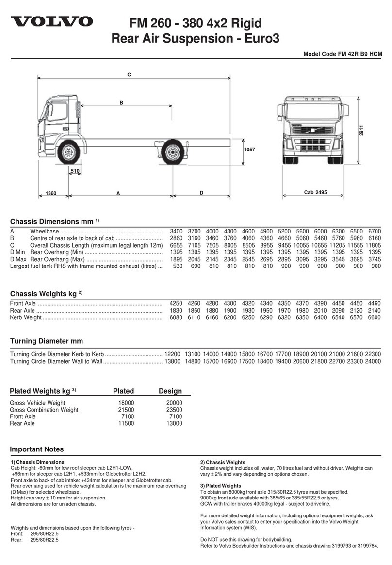
Volvo
Volvo FM 42R B9 HCM Specification sheet
Eibach
Eibach 2021.312 installation instructions
Edelbrock
Edelbrock 70003 installation manual
Edelbrock
Edelbrock 15018 installation instructions
Edelbrock
Edelbrock 5276 installation instructions

Lambo Doors Canada
Lambo Doors Canada Chevrolet Camaro 1993 instructions
Go Rhino
Go Rhino 24371T installation instructions
Edelbrock
Edelbrock 5266 installation instructions
Axxess
Axxess CHTO-013 installation instructions
Ingersoll-Rand
Ingersoll-Rand AUTOMOBILE PARTS LM2350E-X Operator's manual
Edelbrock
Edelbrock 61409 installation instructions
Edelbrock
Edelbrock 71920 installation instructions

