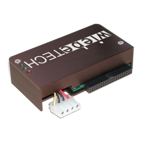
Stec mach2 User manual

MACH2 Parallel ATA (PATA)
1.8-Inch Solid State Drive
Product Manual

ii MACH2 1.8-Inch ATA Solid State Drive
Export Administration Regulations
This document may contain technical data controlled by the U.S. Export Administration Regulations, and
may be subject to the approval of the U.S. Department of Commerce prior to export. Any export, directly or
indirectly, in contravention of the U.S. Export Administration Regulation is prohibited.
The information provided may be subject to United States Export Controls. Such information should not be
downloaded or exported (i) into (or to a national or resident of) Cuba, Iraq, Libya, North Korea, Iran, Syria,
or any other country to which the United States has embargoed goods; or given to (ii), anyone on the United
States Treasury Department’s list of Specially Designated Nationals or the U.S. Commerce Department’s
Table of Deny Orders. by using the information, you represent and warrant that you are not located in,
under the control of, or a national or resident of any such country or on any such list.
Trademark Information
The STEC name, logo and design are trademarks of STEC Inc. No right, license, or interest to such
trademarks is granted hereunder, and you agree that no such right, license, or interest shall be asserted by
you with respect to such trademark. Other product and corporate names mentioned in this document are
used for identification purposes only and may be trademarks or registered trademarks of their respective
companies.
Disclaimer of Liability
The performance information and specifications furnished in this document reflect the engineering
development objectives of STEC Inc. and should be used for comparative analysis and reference purposes.
The content of this document is accurate as of the date of this publication; however, the information
contained herein, including but not limited to any instructions, descriptions and product specifications, is
subject to change without prior notice.
STEC INC. PROVIDES NO WARRANTY WITH REGARD TO THIS DOCUMENT OR ANY
OTHER INFORMATION CONTAINED HEREIN AND HEREBY EXPRESSLY DISCLAIMS ANY
IMPLIED WARRANTIES OF MERCHANTABILITY OR FITNESS FOR ANY PARTICULAR
PURPOSE WITH REGARD TO ANY OF THE FOREGOING. STEC INC. ASSUMES NO
LIABILITY FOR ANY DAMAGES INCURRED DIRECTLY OR INDIRECTLY FROM ANY
TECHNICAL OR TYPOGRAPHICAL ERRORS OR OMMISSIONS CONTAINED HEREIN. IN
NO EVENT SHALL SIMPLETECH BE LIABLE FOR ANY INCIDENTAL, CONSEQUENTIAL,
SPECIAL, OR EXEMPLARY DAMAGES, WHETHER BASED ON TORT, CONTRACT OR
OTHERWISE, ARISING OUT OF OR IN CONNECTION WITH THIS DOCUMENT OR ANY
OTHER INFORMATION CONTAINED HEREIN OR THE USE THEREOF.
Copyright Notice
Copyright ©2007 by STEC Inc. All rights reserved. Information contained in this document, including but
not limited to any instructions, descriptions and product specifications, is company private to STEC and
shall not be modified, used, copied, reproduced or disclosed in whole or in part, in any form or by any
means, electronic or mechanical, for any purpose, without the written consent of STEC Inc.

PRELIMINARY/CONFIDENTIAL
MACH2 1.8-Inch ATA Solid State Drive iii
CONVENTIONS
The following icons are used throughout this document to identify additional
information of which the reader should be aware.
SHOCK HAZARD: This icon indicates the danger of an electrical shock
that may harm or otherwise prove fatal to the user.
CAUTION: This icon indicates the existence of a hazard that could result
in equipment or property damage or equipment failure if the safety
instruction is not observed.
ELECTROSTATICDISCHARGE:Thisicon indicates the possiblepresence
of Electrostatic Discharge (ESD or “static electricity”) that may harm the
internal electronic components. The user is advised to handle the device
only after discharging any possible electrostatic buildup that may be
present.
NOTE: This icon identifies information that relates to the safe operation of
the equipment or related items.
TIP: This icon identifies helpful hints and tips.

PRELIMINARY/CONFIDENTIAL
iv MACH2 1.8-Inch ATA Solid State Drive

PRELIMINARY/CONFIDENTIAL
MACH2 1.8-Inch ATA Solid State Drive v
REVISION HISTORY
Revision Status Summary Sheet
Revision Date Sheet(s) Affected
1.0 07/10/2007 Official release.
1.1 08/10/2007 Page 59: Warranty period updated.

PRELIMINARY/CONFIDENTIAL
vi MACH2 1.8-Inch ATA Solid State Drive

PRELIMINARY/CONFIDENTIAL
MACH2 1.8-Inch ATA Solid State Drive vii
TABLE OF CONTENTS
Conventions . . . . . . . . . . . . . . . . . . . . . . . . . . . . . . . . . . . . . . . . . . . . . . . . . . . . iii
Revision History. . . . . . . . . . . . . . . . . . . . . . . . . . . . . . . . . . . . . . . . . . . . . . . . . .v
List of Tables . . . . . . . . . . . . . . . . . . . . . . . . . . . . . . . . . . . . . . . . . . . . . . . . . . . xi
List of Figures . . . . . . . . . . . . . . . . . . . . . . . . . . . . . . . . . . . . . . . . . . . . . . . . . .xii
Scope . . . . . . . . . . . . . . . . . . . . . . . . . . . . . . . . . . . . . . . . . . . . . . . . . . . . . . . . . .1
Overview....................................................................................................................................1
Audience....................................................................................................................................1
Standards and Reference Documents.......................................................................................2
Electromagnetic Susceptibility...........................................................................................2
Electromagnetic Compatibility............................................................................................2
Commercial Standards ......................................................................................................3
Reference Documents.......................................................................................................3
Manufacturing............................................................................................................................3
Product Description. . . . . . . . . . . . . . . . . . . . . . . . . . . . . . . . . . . . . . . . . . . . . . .4
General Description...................................................................................................................4
ATA-Interface.............................................................................................................................4
Drive Capacities.........................................................................................................................4
Performance..............................................................................................................................4
Performance Characteristics . . . . . . . . . . . . . . . . . . . . . . . . . . . . . . . . . . . . . . .5
ATA (IDE) Bus Modes................................................................................................................5
Endurance..................................................................................................................................5
Wear-Leveling............................................................................................................................5
Bad-Block Management.............................................................................................................6
Data Retention...........................................................................................................................6
Error Detection and Correction..................................................................................................6
Reliability....................................................................................................................................6
Error Rates.........................................................................................................................7
Built-In Self Test (BIST).....................................................................................................7

PRELIMINARY/CONFIDENTIAL
viii MACH2 1.8-Inch ATA Solid State Drive
Mount Time........................................................................................................................7
Seek Time..........................................................................................................................7
Data Transfer Rates..........................................................................................................7
Diagnostic Self Test (DST)................................................................................................8
Repairs..............................................................................................................................8
Preventive Maintenance....................................................................................................8
Electrical Specifications . . . . . . . . . . . . . . . . . . . . . . . . . . . . . . . . . . . . . . . . . . 9
Power Requirements.................................................................................................................9
Power and Current Consumption..............................................................................................9
Drive Power-On Ready Time...................................................................................................10
Power Savings Commands.....................................................................................................10
Power Mode at Power On .......................................................................................................10
Grounding................................................................................................................................10
Interface Specifications. . . . . . . . . . . . . . . . . . . . . . . . . . . . . . . . . . . . . . . . . . 11
SSD Operation ........................................................................................................................11
Write Operations..............................................................................................................11
Read Requests................................................................................................................11
Operating Modes.....................................................................................................................12
I/O Primary and Secondary ATA (IDE) Modes................................................................12
Addressing Modes...........................................................................................................12
40-Pin ATA Bus Connector .....................................................................................................13
Connector Pinout Signals................................................................................................14
ATA Commands . . . . . . . . . . . . . . . . . . . . . . . . . . . . . . . . . . . . . . . . . . . . . . . . 16
Overview..................................................................................................................................16
Standard ATA Commands...............................................................................................16
Standard ATA Command Summary................................................................................18
SMART Support...............................................................................................................23
Identify Device Information......................................................................................................23

PRELIMINARY/CONFIDENTIAL
MACH2 1.8-Inch ATA Solid State Drive ix
Physical Characteristics . . . . . . . . . . . . . . . . . . . . . . . . . . . . . . . . . . . . . . . . . .32
General Physical Characteristics.............................................................................................32
Materials..........................................................................................................................32
Drive Assembly Weight....................................................................................................32
Storage Capacities...........................................................................................................32
Exterior Dimensions.........................................................................................................33
40-Pin ZIF Connector Location........................................................................................34
Environmental Characteristics. . . . . . . . . . . . . . . . . . . . . . . . . . . . . . . . . . . . .35
Overview..................................................................................................................................35
Operating Temperatures..........................................................................................................35
Operating Requirements..................................................................................................35
Non-Operating Requirements..........................................................................................36
Relative Humidity.............................................................................................................36
Altitude Parameters.................................................................................................................36
Restriction of Hazardous Materials..........................................................................................37
Shock and Vibration.................................................................................................................37
Failure Criteria .................................................................................................................37
Random Vibration............................................................................................................37
Shock...............................................................................................................................37
Drop Testing ....................................................................................................................38
Conformal Coating (Optional)..........................................................................................38
Installation . . . . . . . . . . . . . . . . . . . . . . . . . . . . . . . . . . . . . . . . . . . . . . . . . . . . .39
System Requirements..............................................................................................................39
ATA Compatibility ............................................................................................................39
Drive Configuration..........................................................................................................40
Connector Requirements.................................................................................................40
Drive Orientation..............................................................................................................41
Cooling Requirements .....................................................................................................42
Installation Dimensions....................................................................................................43

PRELIMINARY/CONFIDENTIAL
x MACH2 1.8-Inch ATA Solid State Drive
Drive Installation..............................................................................................................44
Grounding Requirements.................................................................................................44
Operating System Specifications.............................................................................................45
Microsoft OS Compatibility..............................................................................................45
Alternative Operating Systems........................................................................................45
System POST, Boot and Resume Times ........................................................................45
Diagnostic Software.................................................................................................................45
SMART Support ......................................................................................................................46
Regulatory Compliance . . . . . . . . . . . . . . . . . . . . . . . . . . . . . . . . . . . . . . . . . . 47
Marking, Approvals and Supporting Documentation...............................................................47
CB Certificate and CB Report..................................................................................................48
Declaration of Conformity........................................................................................................48
Radio Frequency Emissions....................................................................................................48
Radio Frequency Immunity Requirements..............................................................................49
EMI Test Site Correlation.........................................................................................................49
Verification Samples................................................................................................................49
Verification Testing..................................................................................................................49
Electrostatic Discharge (ESD).................................................................................................50
Acceptance Criteria Definitions................................................................................................50
Contact and Ordering Information . . . . . . . . . . . . . . . . . . . . . . . . . . . . . . . . . 51
Contact Information.................................................................................................................51
Ordering Information................................................................................................................51
Index . . . . . . . . . . . . . . . . . . . . . . . . . . . . . . . . . . . . . . . . . . . . . . . . . . . . . . . . . 53
Certification and Warranty . . . . . . . . . . . . . . . . . . . . . . . . . .Inside Back Cover

PRELIMINARY/CONFIDENTIAL
MACH2 1.8-Inch ATA Solid State Drive xi
LIST OF TABLES
1. Error Limits .....................................................................................................7
2. Data Transfer Rates .......................................................................................7
3. SSD Power Requirements..............................................................................9
4. SSD Typical Power Consumption................................................................... 9
5. ATA (IDE) Bus Addressing Modes ...............................................................12
6. ATA Connector Pinout Configuration............................................................ 14
7. Supported ATA Commands..........................................................................16
8. ATA Command Summary............................................................................. 18
9. Identify Device Information...........................................................................23
10. MACH2 SSD Capacities...............................................................................32
11. Drive Assembly Dimensions.........................................................................33
12. Operating Temperatures...............................................................................35
13. Operating Requirements...............................................................................35
14. Non-Operating Requirements.......................................................................36
15. Relative Humidity Criteria.............................................................................36
16. Operating and Non-Operating Altitudes........................................................ 36
17. Random Vibration Levels..............................................................................37
18. Mechanical Shock Conditions and Results...................................................37
19. ATA (IDE) Cable Requirements....................................................................39
20. Recommended Connectors..........................................................................40
21. Default SMART Settings............................................................................... 46
22. Regulatory Marks and Documentation .........................................................47
23. EMI Specification Limits................................................................................ 48
24. ESD Requirements....................................................................................... 50
25. Acceptance Criteria Definitions.....................................................................50

PRELIMINARY/CONFIDENTIAL
xii MACH2 1.8-Inch ATA Solid State Drive
LIST OF FIGURES
1. The MACH2 1.8-Inch ATA Solid State Drive.................................................................1
2. Pin 1 Location on Bus Connector................................................................................13
3. SDD Assembly Dimensions.........................................................................................33
4. 40-Pin ZIF Connector Location....................................................................................34
5. Possible Drive Orientations .........................................................................................41
6. Suggested Air Flow Patterns for Cooling.....................................................................42
7. Exterior Mounting Dimensions.....................................................................................43

PRELIMINARY/CONFIDENTIAL
MACH2 1.8-Inch ATA Solid State Drive 1
SCOPE
Figure 1. The MACH2 1.8-Inch ATA Solid State Drive
Overview
This product manual describes the applications, specifications, and installation of the 1.8-inch
MACH2 ATA Solid State Drive (SSD). See Figure 1.
Audience
This document is intended for system engineers or system designers employed by an Original
Equipment Manufacturer (OEM). This document was therefore written specifically for a technically
advanced audience; it is not intended for end-users that will eventually purchase the commercially
available product. The user, as referenced throughout the document, is primarily concerned with
industrial, commercial or military computing applications.

PRELIMINARY/CONFIDENTIAL
2 MACH2 1.8-Inch ATA Solid State Drive
Standards and Reference Documents
This section discusses the formal standards that may apply to the SSD, including electrical product
standards and military information systems security standards. In addition, this section lists the
reference documents relevant to the ATA-6 interface protocol used for the SSD.
Electromagnetic Susceptibility
The SSD is intended for installation by the user in an appropriate enclosure, i.e., a PC or alternate
enclosure. The enclosure must be designed so that the use of the drive does not impair nearby
electronic equipment within the same enclosure and external to the enclosure.
The user, as previously described under the Audience section, is responsible for choosing,
designing and testing the enclosure so that it is appropriate as previously defined, and complies to
related regulations, such as Subpart B of Part 15 of FCC Rules and Regulations, and the Radio
Interference Regulations of the Canadian Department of Communications.
Electromagnetic Compatibility
Independent laboratories are in the process of confirming that the SSD meets the requirements for
CE Marking. While the drive may have CE Marking, the OEM user must confirm CE Marking for the
productinwhichthedrivehasbeenintegrated.TestsystemsconfirmingtheCEMarkingmayinclude
the following:
Current Microprocessor Diskette Drive
Keyboard Mouse
Monitor Printer
External Modem

PRELIMINARY/CONFIDENTIAL
MACH2 1.8-Inch ATA Solid State Drive 3
Commercial Standards
The SSD complies, in whole or in part, with the following commercial standards:
Reference Documents
The following list of ANSI documents are relative to the SSD:
Manufacturing
S/NZS 3548 Class B UL (Underwriters Laboratories)
BSMI CNS 13438 Class B NEBS Level 3
CAN/CSA-V3/2001.04 (VCCI) IEC 61000-4-2
CE (Conformite Europenne) IEC 61000-4-3
CISPR 22 Class B IEC 61000-4-4
EN 55022 Class B IEC 61000-4-5
EN 61000-3-2 IEC 61000-4-6
EN 61000-3-3 IEC 61000-4-8
FCC Part 15 Class B IEC 61000-4-11
NCITS 340-2000 AT Attachment - 5 with Packet Interface
NCITS 340-2000 T13 e01122r0 (Erratum)
NCITS 1321D ATAttachmentwithPacketInterface-5(ATA/ATAPI-5)
NCITS 1532D ATAttachmentwithPacketInterface-7(ATA/ATAPI-7)
Santa Ana, California
United States of America
ISO 9001 Certified

PRELIMINARY/CONFIDENTIAL
4 MACH2 1.8-Inch ATA Solid State Drive
PRODUCT DESCRIPTION
General Description
The MACH2 1.8-inch ATA Solid State Drive (SSD) is a non-volatile mass storage device. Thedrive
isintendedasareplacementforastandardIDE/ATA-compliantharddiskdrive(HDD).Thedrivecan
be configured as a boot or data storage device. The driveis Plug and Play (PnP) compatible; no
additional device drivers are required to install the drive. The SSD is recognized byPnP-compatible
operating systems and computer BIOS.
ATA-Interface
The SSD can be installed in any operating system environment that supports ATA-6 or greater
devices.Thedriveisconfiguredwithastandard40-pinIDE/ATAconnector, is fullyATA-6compliant,
and conforms to the same mechanical and mounting requirements as standard rotating disk drives.
Drive Capacities
The SSD is available in unformatted memory capacities of 2, 4, 8 and 16 gigabytes. The memory
subsystem is comprised of Single-Level Cell (SLC) NAND flash components.
Performance
TheSSDcanoperateatsustaineddatatransferratesofupto25MBpersecond.Powerconsumption
is kept to a minimum; the SSD can be powered from a single 3.3-volt source. Thesolid state design
eliminates electromechanical noise and delay inherent in traditional magnetic rotating media. The
wear-levelingandbad-blockmappingalgorithmsensureconsistency,accuracy,andintegrityofuser
data. Superior data reliability is achieved through embedded Error Detection and Error Correction
Code (EDC/ECC).

PRELIMINARY/CONFIDENTIAL
MACH2 1.8-Inch ATA Solid State Drive 5
PERFORMANCE CHARACTERISTICS
ATA (IDE) Bus Modes
The SSD supports the following ATA-6 operating modes:
•PIO Mode 4
•Ultra DMA Modes 0 through 4
•Multi-Word DMA 2
•Ultra DMA 5
Endurance
The product life of a SSD is approximately five (5) years when operating within the environmental
specifications.SeeEnvironmentalCharacteristics.Foradetailedlifeexpectancyofthedriveunder
different conditions, please refer to the STEC SSD Life Endurance Calculator. The remaining
conditions are as follows:
Wear-Leveling
The dynamic and static wear-leveling algorithms integrated in the firmware guarantees that erase/
write cycles are evenly distributed across all of the flash memory block locations. Wear-leveling
eliminates repeated writes to the same physical flash memory location, thereby preventing blocks
from premature wear.
Condition Value
Power-On Hours 100%
Active/Idle 90%
Write Percentage 25%
Drive Capacity 8GB
File Transfer Size (Average) 64KB

PRELIMINARY/CONFIDENTIAL
6 MACH2 1.8-Inch ATA Solid State Drive
Bad-Block Management
The bad-block mapping algorithm replaces bad blocks with new ones from available spares. Two
percent (2%) of the flash memory is held in reserve (spare block) for bad block replacement. Bad
blocksinthemediaareflaggedwhendetected.Thenexttimeanattemptismadetoaccessaflagged
block, it is immediately replaced by a spare block. The bad-block mapping function enables data to
be automatically transferred from a bad sector to an available spare block.
Notes:
1STEC Inc. scans for bad blocks during the manufacturing process at the initial installation
of the flash components. Bad blocks are mapped and identified during the manufacturing
process.
2The maximum amount of available user space will not be less than 97% of the total flash
capacity, i.e., the reserved space will not exceed more than 3% of the total drive volume.
Data Retention
Data stored on the SSD will remain valid for 10 years without requiring power support. The unit can
be stored under certain environmental conditions for extended periods without any occurrence of
data degradation. See Environmental Characteristics.
Error Detection and Correction
The Error Detection Code and Error Correcting Code (EDC/ECC) helps maintain data integrity by
allowing single or multiple bit corrections to the data stored in the flash array. If the data in the flash
array is corrupted due to aging or during the programming process, EDC/ECC will compensate for
theerrorstoensurethe deliveryofaccuratedatato thehostcomputer.TheEDC/ECCengineon the
MACH2 SSD is capable of correcting up to 4 bytes in error and detecting up to 5 bytes in error. An
extensiveretryalgorithm isalsoimplemented ontheSSD,so thatsingleeventdisturbancessuch as
ESD or EMF occurring during a read operation can be readily overcome.
Reliability
The following factors affect the reliability statistics of the SSD:
•DC power is maintained as specified in the datasheet.
•Errors caused by the host are excluded from rates.
•Errors from the same causes are counted as 1 block.
•Data stream is assumed random.

PRELIMINARY/CONFIDENTIAL
MACH2 1.8-Inch ATA Solid State Drive 7
Error Rates
Table1liststheerrorlimitspecifications.Whenalldatacorrectionmechanismsareenabled,theerror
ratewillbe sustainedthroughall operatingtemperaturerangesas specified inthefollowing sections.
Table 1. Error Limits
Built-In Self Test (BIST)
The micro-controller tests the controller memory during power-up, and then performs a back-end
statuschecktoverify properflashmemorycontrolleroperations.If a faultconditionisdetectedinthe
flash memory controller, the status of the SSD is reported as failed.
Mount Time
TheamountoftimerequiredtoinitializeandmounttheSSDvariesaccordingtotheoperatingsystem
(Windows®, Linux®, etc.) environment and the storage capacity of the drive.
Seek Time
The SSD has no moving read/write heads or rotating platter. There is no seek time or rotational
latency issues. The SSD dramatically improves transaction throughput, particularly for applications
that are configured to take advantage of the characteristics of the drive.
Data Transfer Rates
The data transfer rate of the SSD depends on the flash controller/flash memory configuration of the
drive.Thescalablearchitectureiscapableofaccommodatingsustainedandburstdatatransferrates
outlined in Table 2.
Table 2. Data Transfer Rates
Error Type Maximum Number of Errors
Recoverable Data Error 1 bit in 1020
Unrecoverable Data Error Less than 1 bit in 1020
Transfer Rate Megabytes/Second
Burst Transfer Rate 40
Sustained Read Throughput 35
Sustained Write Throughput 25

PRELIMINARY/CONFIDENTIAL
8 MACH2 1.8-Inch ATA Solid State Drive
Diagnostic Self Test (DST)
The SSD implements the Diagnostic Self Test (DST) command. DST is invoked with the Send
DiagnosticsPage(1Dh).Whenissued,Byte1,Bits5,6and7(FunctionControlByte)selectbetween
the Short Test (001b) and the Extended Test (010b).
The results are reported on the Self Test Results Log page (10h). If the results are zero, the drive
passedtheDST.A non-zero valueindicatesthe type offailurefound.Theanticipated durationofthe
DST command can be read on the Control Mode page (0Ah).
Repairs
A defective SSD should be replaced. There are no parts, assemblies or subassemblies that can be
repaired by the user. Please see the section titled Certification and Warranty on the inside of the
back cover page. Unauthorized repairs to the SSD will void the warranty.
Preventive Maintenance
No preventative maintenance is required. The drive is sealed at the factory, and there are no parts,
assembliesorsubassembliesthat require preventivemaintenanceonbehalfof theuser.Pleasesee
the section titled Certification and Warranty on the inside of the back cover page. Unauthorized
maintenance to the SSD will void the warranty.
Test Condition Result
Short Test Performs functional checks only.
Extended Test Performs functional checks and a thorough media integrity test.
Other manuals for mach2
2
Table of contents
Other Stec Storage manuals
