Steca TK RW-2 User manual

SOLARTHERMIE - SOLAR THERMAL SYSTEMS - SOLAR TÉRMICO- SOLAIRE THERMIQUE - SOLARE TERMICO
Installation and operating instructions
IFA router
735.800 | Z01 | 10.27 | Subject to change due to technical improvements!
EN
These operating instructions are part of the product.
Read these operating instructions carefully before use.
keep them over the entire lifetime of the product,
and pass them on to any future owner or user of this product.

2735.800 | 10.27
EN
Content
Product information ......................................................................... 3
1 Product description..............................................................4
1.1 Proper usage............................................................................ 4
1.2 Components.........................................................................4
1.3 Functionality.........................................................................5
2 Safety....................................................................................6
2.1 Dangers during assembly/commissioning................................ 6
2.2 Detecting faults ....................................................................... 6
2.3 Exclusion of liability ................................................................. 6
3 Casing overview of the router.............................................7
4 About this manual ...............................................................8
4.1 Applicability............................................................................. 8
4.2 Users........................................................................................ 8
4.3 Description of symbols ............................................................8
5 Mounting and installation ..................................................9
5.1 Mounting the router................................................................ 9
5.2 Installation ............................................................................ 10
6 Internet remote display .....................................................11
6.1 Registration............................................................................ 11
6.2 Displaying the data................................................................ 11
6.3 Settings.................................................................................. 12
7 Using a digital picture frame: initial commissioning........13
7.1 Commissioning for the first time ......................................13
7.2 Language selection ............................................................... 13
7.3 Wireless network ................................................................... 13
7.4 Safety check........................................................................... 13
7.5 Confirming the network connection......................................14
7.6 Detected devices.................................................................... 14
7.7 Setup completed successfully................................................ 14
7.8 Home ..................................................................................... 14
7.9 Images and videos .................................................................14
7.10 SolarShare contents............................................................... 14
7.11 Single image display ..............................................................14
7.12 Slideshow............................................................................... 14
8 Changing the WLAN settings.............................................15
8.1 Appendix: configuration file..............................................15
8.2 How to edit the configuration file.....................................15
8.3 Contents of the configuration file.....................................16
8.4 Restoring the configuration file.............................................21
9 Appendix: customised logo...............................................22
9.1 Requirements to the logo template..................................22
9.2 How to apply the customised logo ...................................22

3
735.800 | 10.27
EN
10 Appendix: Adding your own images to a slideshow........23
10.1 Requirements to your own pictures.......................................23
10.2 Procedure for inserting your own images..............................23
11 Error search ........................................................................24
11.1 General error sources with the IFA router.............................. 24
11.2 Error causes with the picture frame.......................................25
11.3 Causes of faults in the IFA router...........................................25
12 Legal guarantee .................................................................26
13 Technical data.....................................................................26
14 Notes ..................................................................................27
Product information
EC declaration of conformity
"This product conforms to the applicable European directives with
regard to its design and its operating behaviour. This conformity has
been verified. Further information in this regard can be obtained from
your dealer."

4735.800 | 10.27
EN
1 Product description
1.1 Proper usage
The IFA router (Internet remote display router) is a part of the Internet-based digital remote display for the
visualisation of a solar thermal system. The IFA router enables the display of temperature and performance
data of a solar thermal system in your Internet browser window*. In order to be able to display this data,
you will need a PC with Internet connection. For this purpose, the solar thermal controller (referred to
below as "controller") regularly transmits its measured values to the IFA router, which prepares the data
and forwards it to a server. The server archives the data and generates graphics for the Internet browser.
Password-protected server access secures this customer data against unauthorised access.
The current temperature readings of the selected solar energy system are visualised. In addition, the tem-
perature curves are shown in a temperature diagram. When using a heat meter, instantaneous power,
energy balances and CO
2
savings are also displayed.
The prerequisites for the Internet-based remote display are a suitable controller and an Internet connection
via a broadband router with modem** for the IFA router. The broadband router must have a free LAN port
and be continuously connected to the Internet. The controller and the broadband router with modem are
not included in the IFA router delivery package.
The IFA router can also send the graphics via the integrated WLAN to a WLAN-capable digital picture
frame.
* tested browsers: Microsoft Internet Explorer
®
6 and 7, Mozilla Firefox
®
3.0 and 3.5.
** DSL, cable modem or another broadband connection. Analogue modems and ISDN are not supported.
1.2 Components
The remote display consists of the following components:
A suitable solar thermal controller (not included in the IFA router delivery package)
RS232 interface cable with 9-pin D-sub socket, 3-wire
RS232-USB converter with 9-pin D-sub connector, cable with USB connector
IFA router (ASUS WL-500g Premium V2 with special firmware for remote displays)
USB flash drive, with firmware for remote displays
Mains cable for connecting the IFA router to the LAN port of a broadband router
Broadband router with modem** with continuous Internet connection and a free LAN port (not
included in the IFA router delivery package)
PC or laptop with Internet connection and Microsoft Internet Explorer
®
6 or 7, Mozilla Firefox
®
3.0 or
3.5 Internet browser (not included in the IFA router delivery package)
Kodak EasyShare W820 for remote display via WLAN-capable digital picture frames (not included in
the IFA router delivery package)
** DSL, cable modem or another broadband connection. Analogue modems and ISDN are not supported.
1.2.1 ASUS router with firmware for remote displays
The most important component of the remote display is the ASUS WL-500gP V2 IFA router with a special
firmware for remote displays. Since the operating system and application software of the ASUS router have
been replaced by firmware, the original manual for the ASUS router is rendered invalid. The technical data
of the IFA router as well as the approvals and certifications of the IFA router remain valid.
•
•
•
•
•
•
•
•
•

5
735.800 | 10.27
EN
1.3.2 Temperature diagram
Temperature curves
Y-axis: Temperature in
°C or °F. The scaling is
done automatically. X-axis: Time of day in hh:mm. The
scaling is done automatically.
Current temperature
of sensor T1
[°C] or [°F]
T1:
Sensor on terminal 1
of the solar controller
Current thermal performance [kW]
or [Btu/h] -> current time
Legend:
T1: Sensor on
terminal 1 of the solar
controller
For the heat meter:
Daily energy balance [kWh] or
[Btu] -> current date
Annual energy balance [kWh] or
[Btu] -> current year
Total energy balance [MWh] or
[Btu] -> total cumulative value of
the heat meter
Savings in CO2[t] or [tn sh.] ->
calculation on the basis of the
total cumulative value of the heat
meter*
* Sources: Renewable Energy
Sources in Figures - National and
International Development; Federal
Ministry for the Environment,
Nature Conservation and Nuclear
Safety for Europe: CO2 -savings
factor 232 g CO2 /kWhtherm
for North America/Canada:
Hawaiian Electric Co., Inc. HECO
Residential Rebate Program,
Solar water heating system infor-
mation sheet (2007): 1.918 Ibs
CO2 / kWhtherm
1.3 Functionality
The controller cyclically sends the current system data to the IFA router, which forwards the data to a central
server. This server then displays the data in visualised form on the Internet. The data is embedded into the
appropriate system image in the IFA router and the temperature diagram is generated. The system image
and the temperature diagram are sent via the wireless LAN interface from the IFA router to a digital picture
frame.
WLAN
IFA router
Solar
controller
Digital picture frame
Broadband router
with modem Server
The system image and temperature diagram are shown as follows on the digital picture frame:
1.3.1 System image

6735.800 | 10.27
EN
2 Safety
2.1 Dangers during assembly/commissioning
The following risks exist during the commissioning of the router and the picture frame:
Danger to life due to electric shock caused by a damaged mains adapter plug.
During work on the controller, the safety instructions for the controller instructions must also be fol-
lowed.
Ensure that the permissible ambient conditions at the installation site are maintained.
2.2 Detecting faults
As soon as it becomes evident that safe operation is no longer guaranteed (e.g. visible damage),
remove the device from the mains supply immediately.
2.3 Exclusion of liability
The manufacturer can neither monitor the compliance with this manual nor the conditions and methods
during the installation, operation, and usage of the devices. Improper installation of the system may result
in damage to property and, as a consequence, bodily injury.
Therefore, the manufacturer assumes no responsibility or liability for any loss, damage or costs arising
from or in any way related to incorrect installation, faulty performance of the installation work, improper
operation as well as wrong use.
Likewise, the manufacturer assumes no responsibility for infringement of patent rights or violations of
other rights of third parties arising from the use of the devices.
The manufacturer reserves the right to make changes to the product, technical data or installation and
operating instructions without prior notice.
The manufacturer assumes no responsibility for the content of the images uploaded. The responsibility for
the content of the uploaded images lies solely with the operator.
•
•
•

7
735.800 | 10.27
EN
42
31
LAN
AIR WAN
NOTE
*Applies only to wireless LAN operation: When using WPA/WPA2 encryption, the "AIR" LED may be unlit
after having booted the router if no communication takes place with the picture frame!
Power supply mains adapter plug
USB port for USB flash drive
USB port for data transfer
to the solar controller
Aerial connection
EZSETUP: The wireless LAN
interface is switched on or off by
pressing briefly. If the button is
kept pressed down for at least
5 seconds, the version number
display appears on the screen of
the picture frame. To prevent the
picture with the version numbers
from being overwritten within a
short period of time, the con-
troller should be in "off" mode
during the procedure.
RESTORE: Quickly pressing the
button triggers a reset of the
image generation. This may be
necessary if a cable is pulled or
becomes loose or a display error
occurs. Pressing the button for at
least 10 seconds will restore to the
default condition and all stored
data will be deleted.
LAN port: is not currently supported
with the special firmware for remote
displays.
LAN: is not used for firmware
for remote displays.
AIR: LED continuously lit: wireless LAN is active*
LED flashes: transferring data / receiving
LED off: wireless LAN inactive
42
31
LAN
AIR WAN
: LED continuously lit:
device ready for operation
LED flashes: device initialising
system
3 Casing overview of the router
WAN port: for connection to the LAN
port of the broadband router
WAN: LED continuously lit: WAN is active
LED flashes: transferring data / receiving
LED off: WAN cable not connected

8735.800 | 10.27
EN
4 About this manual
4.1 Applicability
This manual covers installation, commissioning, and operation of the
IFA router for remote display of a solar thermal system. The relevant
instructions from the respective manufacturers are to be followed for
the remaining components, e.g. broadband router, picture frame and
solar control.
4.2 Users
The remote display and the IFA router can be operated by the user by
following these instructions.
Use the remote display and the IFA router only after you have carefully
read and understood the operating instructions and the safety instruc-
tions. Adhere to all safety instructions and consult professional person-
nel in the event of any ambiguities.
This device is not intended for persons (or children) with physical, sen-
sory, or mental disabilities, or who have inadequate experience and
knowledge, unless they were instructed in the proper use of the device
and initially supervised by a person who is responsible for their safety.
Children should not be left alone with the device, to ensure that they
do not play with it.
4.3 Description of symbols
4.3.1 Structure of the warning notices
SIGNAL WORD
Type, source and consequences of the danger!
Measures for avoiding danger.
4.3.2 Danger levels in warning notices
Danger levels Likelihood of
occurrence Consequences
resulting from non-
compliance
DANGER Imminent
threat of danger Death, serious
bodily injury
WARNING Possible
threat of danger Death, serious
bodily injury
CAUTION Possible
threat of danger Minor
bodily injury
CAUTION Possible
threat of danger Property damage
4.3.3 Notes
NOTE
Note on easier and safer working habits.
Measures for easier and safer working habits.
9
735.800 | 10.27
EN
4.3.4 Other symbols and markings
Symbol Meaning
✓Condition for action
Call to action
Result of action
• List
Emphasis Emphasis
5 Mounting and installation
NOTE
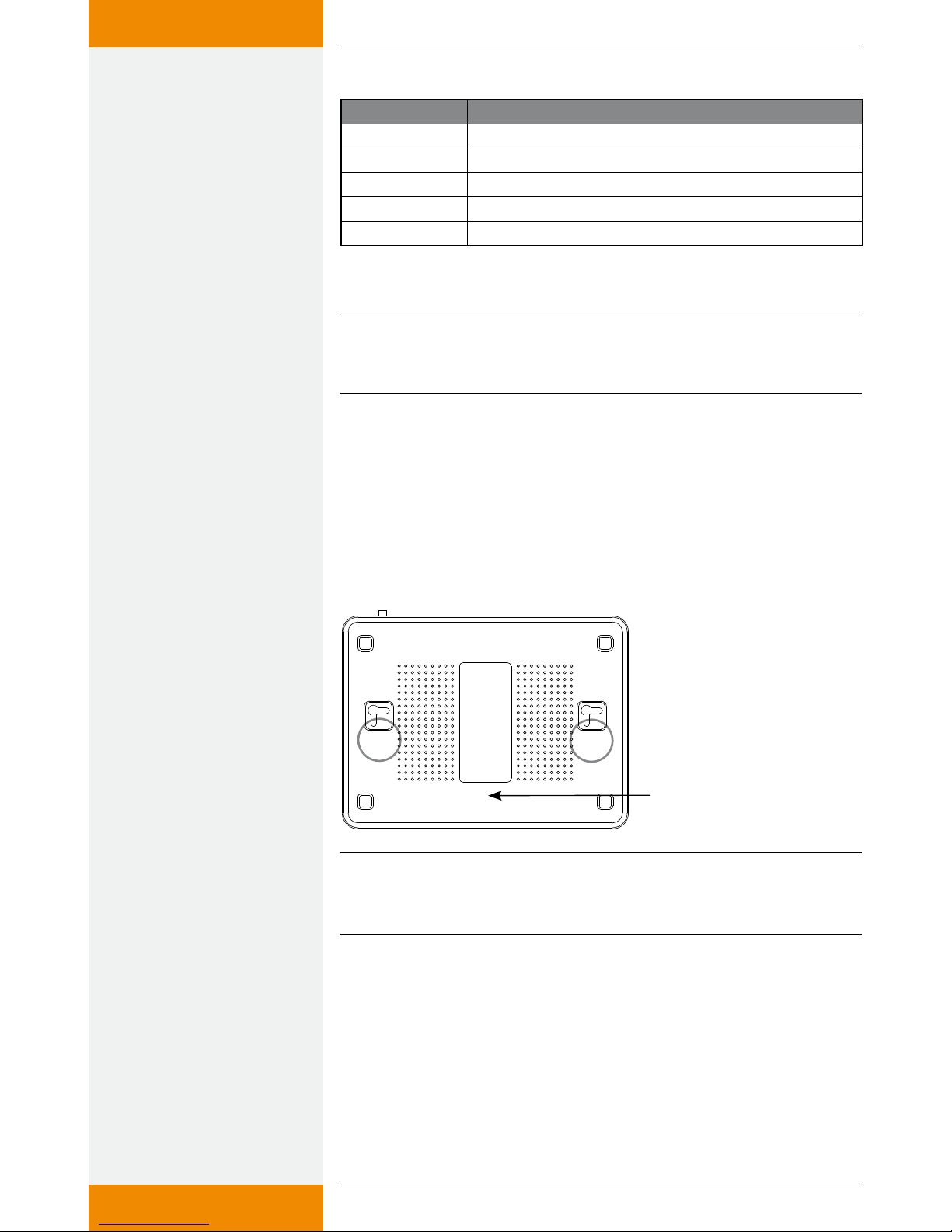
Please note the MAC address before mounting. This is on the rear side of
the IFA router and is required for registration (see drawing below).
5.1 Mounting the router
The device can be mounted on the wall or the ceiling.
1. Locate the mounting holes on the underside.
2. Mark the two upper holes on the wall or on a raised level surface.
3. Tighten the two screws on the wall far enough that only a residual
length of 0.5 cm protrudes.
4. Hook the mounting holes of the ASUS WL-500gP V2 onto the
screws.
Reading the MAC address
NOTE
Re-align the screws if you are not able to mount the ASUS wireless LAN
router, or if it is too loose.

10 735.800 | 10.27
EN
5.2 Installation
In the following, the individual steps for installing the remote display are
described. Please follow the sequence.
1. Connect the RS232 interface cable to the controller. Please also see
the instructions for the controller. Pay attention to the wire colours.
DANGER
Risk of death by electrocution!
Prior to opening the controller casing, disconnect the controller from
the mains.
2. Connect the RS232 interface cable to the RS232-USB converter.
3. Plug the USB connector of the RS232-USB converter into the USB port
of the IFA router for data transfer.
4. Plug the USB flash drive into the USB port of the IFA router.
5. Mount the antenna on the IFA router (only when using a digital pic-
ture frame).
6. Connect the power supply of the IFA router to the IFA router and
connect to the mains.
NOTE
The IFA router needs about 1 minute for system initialisation after
switching it on. The IFA router is ready for use when both the power
LED and the "AIR" LED are permanently lit.
Exception: In the WPA or WPA2 mode, "AIR" will only light up when you
try to establish a connection between the picture frame and the IFA
router.
7. Connect the controller to the mains.
DANGER
Risk of death by electrocution!
Make sure that the controller is closed.
8. Please note only when using a digital picture frame: Assemble the dig-
ital picture frame and put it into operation. See the Kodak EasyShare
W820 user manual and Chapter 7 "Using a digital picture frame: com-
missioning".
Rx Tx
T
Terminal diagram of the
RS232 interface
Orange
Green
Red
11
735.800 | 10.27
EN
9. Connect the mains cable to the WAN port of the IFA router and to
the LAN port of the broadband router. The address is issued in the
IFA router either via DHCP (automatic issue of the IP address) or can
be given statically in the configuration file, see Chapter 8.3.
10. Registration: Please contact the seller or specialist dealer and give
them the MAC address on the rear side of your IFA router (see draw-
ing Chapter 5.1). You will then receive your access data: your user-
name, password and web address.
6 Internet remote display
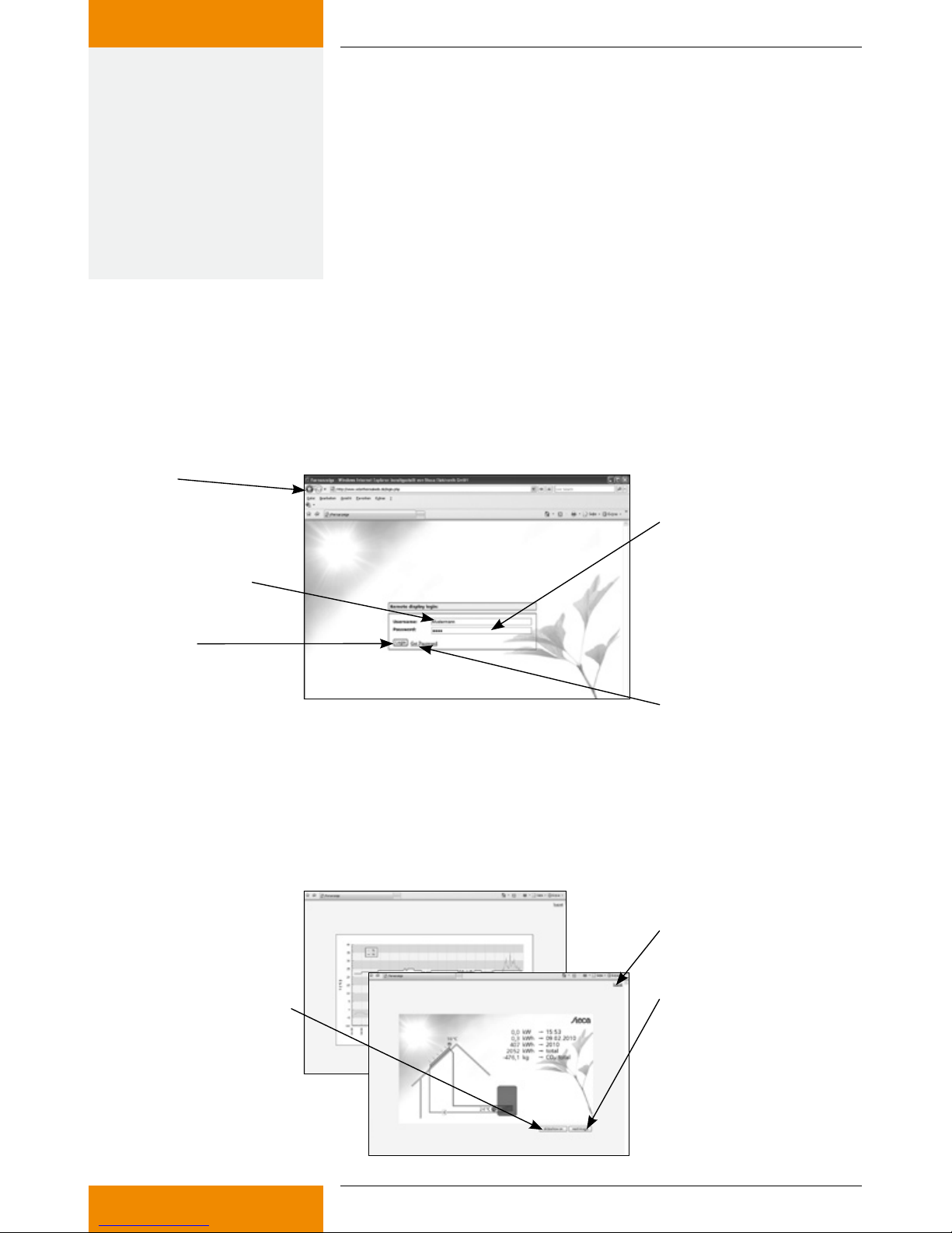
6.1 Registration
In order to be able to operate the Internet remote display, you must first register the IFA router. Contact
the seller or specialist dealer and give them the MAC address on the rear side of your IFA router (see
drawing Chapter 5.1). They will then give you your access data: Your username, display password and a
settings password.
Web address:
www.solarthermalweb.de or
www.solarthermalweb.com
Username
Password:
A display password is given to
enable you to display the data.
The settings password is required
if you wish to make individual
settings on the display.
Login: Log in
GetPassword:
Click here if you have forgotten
your password.
6.2 Displaying the data
In order to display and analyse data on www.solarthermalweb.de or www.solarthermalweb.com, log in
with your username and the display password.
The data in the solar energy system is shown in a system image, and in a temperature diagram, see Chapter
1.3.1 "System image" and 1.3.2 "Temperature diagram". With the Internet remote display, the images can
be displayed in a slideshow or changed manually.
Next image:
The image display
is changed manually.
Slideshow on:
the slideshow has been selected.
The slideshow is stopped when
you press the button.
Logout: Log out
12 735.800 | 10.27
EN
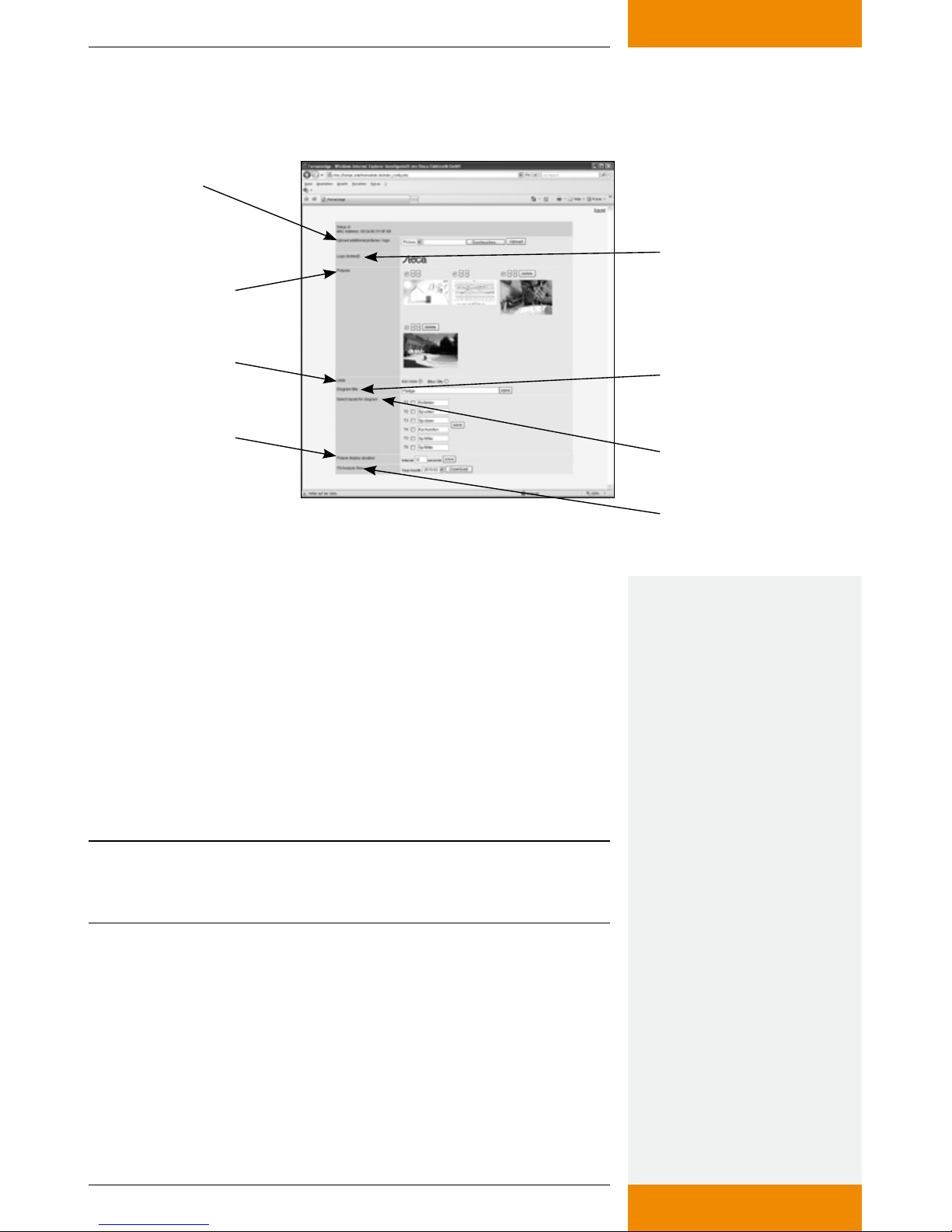
6.3 Settings
With the Internet remote display, the image sequence can be adapted and supplemented with your own
images. Log in to www.solarthermalweb.de or www.solarthermalweb.com with your username and the
settings password.
Upload additional
pictures / logo:
Upload additional
pictures, each with a
maximum size of 1 MB. Logo:
Logo from your dealer
Pictures:
Uploaded image data
Web form:
Length of time a picture
is displayed during the
slideshow
TS Analyzer Files:
Download the measured
values for the month
Select inputs for diagram:
Sensor selection
Units: Physical units Diagram title:
Diagram title of your display
Upload additional pictures / logo: You have the option of showing
your own images in the slideshow in addition to the system image
and temperature diagram. To do so, the additional images must be
uploaded onto the server. To upload an image, select "Image" in the
selection window, then click on "Search" to select and upload the
required image. The image is added on to the end of the slideshow.
You can upload maximum 10 images onto the server, with a maxi-
mum image size of 1 MB.
If authorised by the seller or specialist dealer, you can insert your
customer-specific logo into the system image. To do so, select "Logo"
instead of "Image" in the selection window. If you have been blocked
from incorporating a customer-specific logo by the seller or specialist
dealer, the word "(locked)" will be shown in the "Logo" field.
NOTE
Requirement for the image/logo: only images in the JPEG format can be
used. The suffix for each of the images must be "jpg".
Logo: The logo currently displayed is shown.
Pictures: Here, both the system images and all your own images on
the server are shown.
The position, and therefore the sequence, of the images in the
slideshow can be changed using the "<" and ">" arrow buttons. Press
"delete" to delete the image from the server. The checkmark is used to
deactivate an image, but the image is not deleted from the server.
Units: The physical units for output and energy can be shown in met-
ric units kW / kWh or in Btu/h / Btu as commonly used in the USA.

13
735.800 | 10.27
EN
Diagram title: A diagram title can be defined which is displayed
above the temperature diagram. The required title is written into the
line with a maximum of 50 characters, and stored with "save".
Select inputs for diagram: Additional temperature sensors can only
be shown in the temperature diagram by setting the control check-
mark, and not in the system image. If no sensor has been selected,
the standard setting is used, i.e. the solar energy system sensors are
shown.
Additionally, individual names can be defined for the temperature
sensors and shown in the legend. The required designation is writ-
ten into the appropriate line with a maximum of 12 characters, and
stored with "save".
Web form: The time between two image changes during the slide-
show can be set using "Images refresh rate".
TS Analyzer Files: The measured values of the controller which are
stored on the server can be downloaded as a ZIP file by pressing
"Download". In order to limit the data load of the file, the individual
download is restricted to one month.
7 Using a digital picture frame: initial
commissioning
The IFA router can also send the graphics via the integrated WLAN inter-
face to a WLAN-capable digital picture frame.
7.1 Commissioning for the first time
When starting the digital picture frame for the first time, please see the
Kodak EasyShare W820 user's guide "Getting started".
7.2 Language selection
See the user's guide for the Kodak EasyShare W820 "Getting started",
setting the language. Once the language has been selected, the digital
picture frame will start looking for wireless networks.
7.3 Wireless network
All available wireless networks will be displayed.
Select the network "TK RW2 Net" and press "OK".
7.4 Safety check
The system performs a safety check. The picture frame indicates that the
network is not secured since the delivery status of the remote display is
without any preset encryption.
There is no factory preset encryption because no security-relevant infor-
mation is being transmitted. The message box is closed by selecting
"Finish". If you want to encrypt image data, see section 8.3.11, "Wireless
LAN encryption".

14 735.800 | 10.27
EN
7.5 Confirming the network connection
A successful connection to the wireless network "TK RW2 Net" is con-
firmed. The digital picture frame is now asking to install the EasyShare
software on the IFA router.
Prompt the installation with "Search now".
7.6 Detected devices
The detected devices are listed. Select "SolarShare" and complete the
installation with "FINISHED".
7.7 Setup completed successfully
The successful installation is confirmed again.
The confirmation can be closed from the menu window "[Home]".
7.8 Home
You will see the home page of the setup. To enable the display of the
system images, select "Images and videos".
7.9 Images and videos
Available images / videos are displayed. Select "SolarShare" and confirm
with "OK".
7.10 SolarShare contents
The contents of "SolarShare" is displayed as a thumbnail. The contents
consist of the system image with the current temperature values and
the daily diagram.
Either a single image can be displayed or a slide show can be started.
7.11 Single image display
For the single image display, simply select the desired image and confirm
with "OK".
This opens the selected image permanently, e.g. the "System image".
7.12 Slideshow
The slideshow is started from the menu window "[Start]". The system
image and the daily diagram are displayed alternatingly in 5-second
intervals.
In addition, separate images can be embedded in the slideshow (see
chapter 10 "Appendix: Adding your own images to a slideshow"). The
default duration of the image display is 5 seconds but it can be changed
in the setup window of the picture frame.
15
735.800 | 10.27
EN
8 Changing the WLAN settings
If another wireless network is run within range of the IFA router, it may
be necessary to change the channel or the network name of the WLAN
network in order to prevent faults occurring. In addition, the encryption
of the WLAN network can be adjusted as required.
To do this, the configuration file "Config.wri" on the USB flash drive
needs to be modified (see section 8.1 "Appendix: configuration file").
NOTE
Config.wri may only be opened with Microsoft® WordPad!
Please note that after changes have been made to the WLAN settings,
the network settings of the picture frame need to be re-adjusted.
8.1 Appendix: configuration file
The "Config.wri" configuration file on the USB flash drive contains all
settings which can be changed by the end customer.
The file "Config.wri" is located in the directory: Share -> Config.
The "Config.wri" file must be opened with Microsoft®WordPad in order
to edit it.
8.2 How to edit the configuration file
The IFA router and digital picture frame have to be disconnected
from the mains.
Remove the USB flash drive from the IFA router and plug it into the
USB port of a PC.
Open the Config.wri file with Microsoft®WordPad, edit it and save
with the same name.
Remove the USB flash drive from the USB port of your PC and plug
it into the IFA router.
Connect the IFA router to the mains and wait until it is ready for
operation.
Connect the digital picture frame to the mains and make any neces-
sary changes to the settings (see section 7, "Using a digital picture
frame: initial commissioning").
NOTE
Config.wri may only be opened with Microsoft®WordPad!
The USB flash drive may not be formatted!

16 735.800 | 10.27
EN
8.3 Contents of the configuration file
;########################################
;### Fernanzeige Konfiguration / Remote display configuration ###
;########################################
;1: Einstellungen bezueglich Fernanzeige / Settings regarding remote
display
[FERNANZEIGE_CONFIG]
;1.1: Anlagenbild (aktiv: 1 / inaktiv: 0) / System image (active: 1 / inactive:
0)
system_active = 1
;1.2: Zeittagesdiagramm (aktiv: 1 / inaktiv: 0) / daily time diagram (active:
1 / inactive: 0)
diagram_active = 1
;1.3 Ueberschreibe Bitmaske Eingaenge Diagram / Override bitmask
Inputs diagram (T6|T5|T4|T3|T2|T1) ... exp. „0|0|1|1|1|1“
;diagram_bitmask_override = „0|0|1|1|1|1“
;1.4 Ueberschreibe CO2 Faktor / Override CO2 factor
;factor_CO2 = 0.232
;1.5: Diagrammtitel / diagram title (50 Zeichen/50 chars)
diagram_title = „“
;1.6: Texte fuer Diagrammlegende / Texts for diagram legend
(12 Zeichen/12 chars)
diagram_t1_text = „T1“
diagram_t2_text = „T2“
diagram_t3_text = „T3“
diagram_t4_text = „T4“
diagram_t5_text = „T5“
diagram_t6_text = „T6“
;1.7: Einheiten im Systembild / units in system image („kw“ oder „btu“)
system_units = „kw“
;#########################################
;### WLAN Konfiguration / WLAN Configuration ###
;#########################################
;2: Einstellungen bezueglich Wireless LAN / Settings regarding wireless
LAN
[WLAN_CONFIG]
;2.1: WLAN nach Einschalten des Routers ausschalten (ja: 1 / nein: 0) /
disable wireless after power on (yes: 1 / no: 0)
wlan_disabled = 0

17
735.800 | 10.27
EN
;2.2: WLAN Netzwerkname / WLAN network name
ssid = „TK RW2 Net“
;2.3: WLAN Kanal (Wert zwischen 1 und 11) / WLAN channel (Value
between 1 and 11)
channel = 6
;2.4: WLAN Verschluesselung / WLAN encryption („OPEN“, „WEP“,
„WPA“, „WPA2“)
encryption = „OPEN“
;2.5: WLAN Passwort / WLAN password (OPEN: „“, WEP: 5 o. 13 Zeichen
/ Chars, WPA/WPA2: 8 - 63 Zeichen / Chars)
passphrase = „“
;#########################################
;### WAN Netzwerk Konfiguration / WAN Network Configuration ###
;#########################################
;3: WAN Einstellungen / WAN settings
[WAN_CONFIG]
;3.1: Verwendetes Protokoll fuer IP Vergabe („static“ / „dhcp“)
wan_protocol = „dhcp“
;3.2: Verwendung nur wenn 3.1 „static“: Angabe der IP Adresse / Only if
3.1 „static“: Declaration of IP address
wan_ip_addr = „“
;3.3: Verwendung nur wenn 3.1 „static“: Angabe der Subnetmaske /
Only if 3.1 „static“: Declaration of subnet mask
wan_netmask = „“
;3.4: Verwendung nur wenn 3.1 „static“: Angabe der Gateway Adresse /
Only if 3.1 „static“: Declaration of gatway address
wan_gateway = „“
8.3.1 System image
;1.1: System image active: 1, inactive: 0
system_active = 1
System_active is preset in the factory to 1, so the system image can be
selected and displayed in the digital picture frame.
If system_active is set to 0, the system image cannot be selected in the
digital picture frame.

18 735.800 | 10.27
EN
8.3.2 Time diagram
;1.2: Time diagram active: 1, inactive: 0
diagram_active = 1
Diagram_active is preset in the factory to 1, so the daily diagram can be
selected and displayed in the digital picture frame.
If diagram_active is set to 0, the daily diagram cannot be selected in the
digital picture frame.
8.3.3 Sensor selection for the temperature diagram
;1.3 Override bitmask inputs (T6|T5|T4|T3|T2|T1) e.g. "0|0|1|1|1|1"
;diagram_bitmask_override = "0|0|1|1|1|1"
The selection of the temperature sensors which are shown in the tem-
perature diagram can be changed.
To do so, the semicolon before the phrase "diagram_bitmask_override"
must be deleted and a sensor selection must be defined as shown in
the example. The selection is defined by six characters which are each
separated by a "|". The characters may only have the value "0" or "1"; "0"
means sensor "not selected", and 1 means sensor "selected".
In the example "0|0|1|1|1|1", the sensors T1 to T4 would be selected,
while T5 and T6 would be deactivated.
If you wish to return to the standard settings, you must re-write a semi-
colon in front of the phrase "diagram_bitmask_override".
8.3.4 CO2 factor
;1.4 Override CO2 factor
;factor_CO2 = 0.232
If you wish to use another factor than 0.232 Kg/kWh to calculate the
CO2 value, this factor can be defined.
To do so, the semicolon in front of the phrase "factor_CO2" must be
deleted and a factor defined as shown in the example. The physical unit
of the factor is kg/kWh.
If you wish to return to the standard settings, you must re-write a semi-
colon in front of the phrase "factor_CO2".
8.3.5 Diagram title
;1.5: Diagram title (50 characters)
diagram_title = ""
You can specify a title for the temperature diagram which is shown
above the temperature curves. The diagram title is limited to a maxi-
mum of 50 characters.
In the factory, the diagram_title is set to "", i.e. no title is defined.
The title is defined by entering characters within the quotations marks,
e.g. diagram_title = "My solar energy system"

19
735.800 | 10.27
EN
8.3.6 Diagram legend
;1.6: Texts for diagram legend (12 characters)
diagram_t1_text = "T1"
diagram_t2_text = "T2"
diagram_t3_text = "T3"
diagram_t4_text = "T4"
diagram_t5_text = "T5"
diagram_t6_text = "T6"
Names can be defined for the temperature sensors for the legend in the
temperature diagram. The texts for the temperature sensors are each
restricted to a maximum of 12 characters.
The legend texts diagram_t1_text...diagram_t6_text are set in the fac-
tory to "T1"..."T6".
The names are defined by changing the characters within the quotation
marks, e.g. diagram_t1_text = "Collector"
8.3.7 Units for output/energy
;1.7: Units in system image ("kw" or "btu")
system_units = "kw"
The physical units for output and energy can be converted from metric
units to those units commonly used in North America.
In the factory, system_units is set to "kw", i.e. the units are shown in W
or Wh.
If system_units is set to "btu", the units are shown in Btu/h or Btu.
The unit prefixes, e.g. "k" (kilo), "M" (Mega) etc. are given automatically.
8.3.8 WLAN after turning on the IFA router
;2.1: Disable wireless LAN after power on (yes: 1 / no: 0)
wlan_disabled = 0
Wlan_disabled is preset to 0, so the wireless LAN is automatically ena-
bled after restarting the IFA router.
If wlan_disabled is set to 1, the wireless LAN of the IFA router is inactive
after restarting.
8.3.9 Wireless LAN name
;2.2: Wireless LAN name
ssid = "TK RW1 Net"
The ssid is preset to "TK RW2 Net", so the wireless network of
the IFA router appears on the picture frame under the name
"TK RW2 Net". A change of name requires a new assignment of the net-
work in the digital picture frame.
NOTE
The name must always be given in quotation marks, e.g. "My solar
energy system".
20 735.800 | 10.27
EN
8.3.10 Wireless LAN channel
;2.3: Wireless LAN channel (value between 1 and 11)
channel = 6
The factory preset value for channel is set to 6. The value can be changed
between 1 and 11.
8.3.11 Wireless LAN encryption
By default, the IFA router is supplied without wireless LAN encryption
because no security-relevant information is being transmitted. If desired,
the network can be encrypted with WEP, WPA or WPA2.
To do this, the configuration file "Config.wri" on the USB flash drive
needs to be modified (see section 8.1 "Appendix: configuration file").
The settings for the wireless LAN encryption are made in "Config.wri",
under "Wireless LAN encryption". If a wireless LAN encryption is selected,
a password of your choice must be set under "Wireless LAN password".
This password is required for access authorisation for the digital picture
frame.
NOTE
Config.wri may only be opened with Microsoft® WordPad!
;2.4: WLAN encryption ("OPEN", "WEP", "WPA", "WPA2")
encryption = "OPEN"
Factory preset value for encryption is "OPEN", so the network is not
encrypted.
If the network is to be encrypted, you must set
encryption = "WEP" for WEP encryption,
encryption = "WPA" for WPA encryption,
encryption = "WPA2" for WPA2 encryption.
8.3.12 Wireless LAN password
;2.5: Wireless LAN password (OPEN: "", WEP: 5 or 13 characters,
WPA / WPA2: 8 to 63 characters)
passphrase = ""
The factory preset value for the password is " " because the network is
unencrypted by default.
If you chose WEP encryption, the password must be entered as a 5-digit
or 13-digit password, for example
password = "12345"
If you chose WPA or WPA2 encryption, the password must be entered as
an 8 to 63-digit password, for example
password = "12345678"
NOTE
Only use numbers and letters for the password. A distinction is made
between uppercase and lowercase letters.
•
•
•
Table of contents


