Steelman 95218 User manual

Rev. 2 06/18
Instruction Manual
9 Liter Capacity Manual and Pneumatic Fluid Extractors
Model 95218 Model 95219
Manual Fluid Extractor Pneumatic Fluid Extractor
Read all instructions carefully prior to operating this piece of equipment.

2

3
Specifications
Warnings and Cautions
Read all instructions carefully prior to operating this piece of equipment.
Your new fluid extractor is designed to assist in the trouble-free removal of various liquids,
including engine oil, gear oil, transmission oil, brake fluid, power steering fluid, engine
coolant, and many other common automotive fluids.
WARNING! Do NOT use this fluid extractor with gasoline or any other highly
combustible liquid.
CAUTION!
Do NOT use this fluid extractor to store any poisonous or highly
acidic/alkaline liquids, chemicals, or solvents.
Do not throw, drop or mishandle the unit.
Do not disassemble, tamper with or modify the unit for any purpose other
than what is described in this manual.
Do not store either the unit or suction tubes near or in areas of high
temperatures, direct sunlight, rain or snow.
Do not store liquids in the extractor.
Drain and wash the extractor after each use.
Always wear appropriate Personal Protective Equipment when working
with this tool.
Always wash your hands after using or handling this tool.
95218 95219
Capacity 9L 9L
Working Pressure N/A 70-170 PSI
Air Consumption N/A 5 CFM

4
P
O
N
D
J
L
K
I
G
E F
H
A
C
M
Part Nomenclature
A. Hand Pump (95218 only)
B. Release Button (95218 only)
C. Handle
D. Cover Housing
E. Push Button (95219 only)
F. Air Valve (95219 only)
G. Fluid Inlet Coupler
H. Muffler (95219 only)
I. Fluid Outlet Housing
J. Reservoir Tank
K. Tube Storage Unit
L. Base
M. Footboard
N. Brake Bleeding Tube
O. Extraction Tube
P. Main Suction Tube
B

5
Instructions for Use - Oil Extraction
1. Park vehicle on level surface and apply vehicle’s emergency brake.
2. Start the engine and idle the vehicle until it reaches normal operating
temperature. Shut engine off.
3. Remove engine oil dipstick from the vehicle.
4. Insert Extracting Tube (O) into the dip stick hole until it reaches the
bottom of the oil pan.
5. Insert Main Suction Tube (P) into Fluid Inlet Coupler (G).
6. Connect Main Suction Tube (P) to Extracting Tube (O) using the Extracting
Tube adapter (rubber coupler).

6
Steps 7-9 are for the Pneumatic Extractor (95219) only. For the Manual
Extractor (95218), proceed to step 10.
7. Make sure Air Valve (F) is
in the closed position
(perpendicular to inlet
hose). Connect the air
hose to the Air Valve and
turn on the air compressor.
8. Turn Air Valve Switch (F)
to the open position (¼
turn clockwise) and press
the Push Button (E).
9. When the Reservoir Tank (J) is full, the extractor will automatically shut
off. If extractor does not become completely full, turn Air Valve (F) to the
off position in order to stop the extractor. Proceed to Step 12.

7
Steps 10-11 are for the (95218) Manual Extractor only.
10. Lift Handle (A) to top position and
return back to bottom position. Repeat
this pumping action to create vacuum
in the Reservoir Tank (J). Oil will begin
extracting into Reservoir Tank (J).
11. When oil in Reservoir Tank (J) reaches
“full” position, the Handle (A) of the
hand pump will become difficult to
depress due to back-pressure in the
Reservoir Tank. Press the Release
Button (B) to return the Handle (A) to its bottom position.
Steps 12-15 are for both Manual and Pneumatic Extractors.
12. Disconnect Extracting Tube (O) and Main
Suction Tube (P) from Fluid Inlet Coupler (G).
13. Remove Extracting Tube (O) from dip stick
hole.
14. Remove Fluid Inlet Coupler (G) from Fluid
Outlet Housing (I).
15. Dispose of fluids in accordance with the laws
and regulations of your state.

8
Instructions for Use – Brake Bleeding
WARNING! Before using this tool with your brake system, ensure that all
components of the extractor are clean. Failure to do so may result in brake
fluid contamination and may potentially cause brake system failure.
CAUTION! Refer to the manufacturer’s recommended procedures for brake
bleeding. In some cases, specialized tools and/or equipment may be necessary.
Before Bleeding Brakes
Bleed brake system in following order:
1. Master cylinder (if necessary)
2. ABS controller (if necessary)
3. Wheel cylinders and calipers in manufacturer recommended order.
Bleeding Brakes
1. Park vehicle on level surface and apply vehicle’s emergency brake.
2. Make sure master cylinder reservoir is full of manufacturer specified
brake fluid and more new fluid is available to top off reservoir during
bleeding procedure. Also be sure to clean off bleeder fittings before
beginning bleeding procedure.
3. Remove bleeder fitting cap and place wrench on the nut of the bleeder
screw.
4. Connect Brake Tube w/ Rubber Fitting (N) to vehicle’s bleed screw. (Note:
Refer to manufacturer’s manual for proper bleed order. Typically, you
should bleed brakes from farthest from master cylinder to closest.)
5. Insert Main Suction Tube (P) into Fluid Inlet Coupler (G).
6. Connect Main Suction Tube (P) to Brake Bleeding Tube (N).

9
Steps 7-12 are for the Pneumatic Extractor only. For the Manual Extractor,
proceed to step 13.
7. Make sure Air Valve (F) is in the closed position. Connect the air hose to
the Air Valve and turn on the air compressor.
8. Turn Air Valve (F) to the open position and press the Push Button (E).
9. Open the bleeder screw slightly, just enough to cause fluid to flow into
the Brake Bleeding Tube (N).
10. Evacuate fluid until no air bubbles are present in the clear tube and then
tighten the bleeder screw.
11. Top off master cylinder reservoir and proceed to next brake according to
manufacturers bleeding order. Repeat until bleeding of all brakes has
been completed.
12. When the Reservoir Tank (J) is full, the extractor will automatically shut
off. If extractor does not become completely full, turn the Air Valve (F) to
the off position in order to stop the extractor. Proceed to Step 18.
Steps 13-17 are for Manual Extractor only.
13. Open the bleeder screw slightly, just enough to cause fluid to flow into
the Brake Bleeding Tube (N).
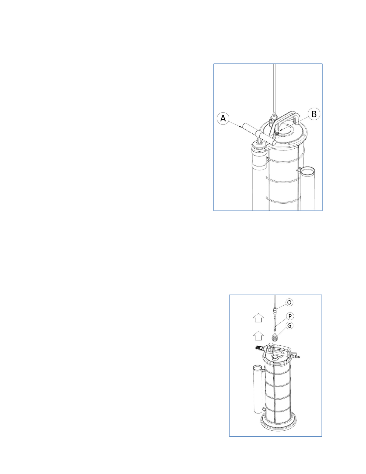
14. Lift Handle (A) to top position and return back to bottom position. Repeat
this pumping action to create vacuum in the Reservoir Tank (J). Brake fluid
will begin transferring into Reservoir Tank (J).
15. Evacuate fluid until no air bubbles are present in the clear tube and then
tighten the bleeder screw.
16. Top off master cylinder reservoir and proceed to next brake according to
manufacturers bleeding order. Repeat until bleeding of all brakes has
been completed.
17. When brake fluid in Reservoir Tank (J) reaches “full” position, the Handle
(A) of the hand pump will become difficult to depress due to back-
pressure in the Reservoir Tank (J). Press the Release Button (E) to return
the Handle (A) to its bottom position.

10
Steps 18-20 are for both Manual and Pneumatic Extractors.
18. Disconnect Extracting Tube (O) and Brake Bleeding Tube w/ Rubber Fitting
(N) from Fluid Inlet Coupler (G).
19. Remove Brake Bleeding Tube (N) from bleeder fitting.
20. Remove Fluid Inlet Coupler (G) from Fluid Outlet Housing (I). Properly
dispose of fluids in accordance with the laws and regulations of your state.
21. Rinse the Reservoir Tank after finishing with the extractor.

11
Troubleshooting
Problem Resolution
1
When the extractor is on, or
pumping, it does not extract
fluid.
(a) Check air hose for sufficient
pressure (minimum 70 PSI).
(b) Make sure all tubes are properly
connected and are not damaged or
blocked by debris.
(c) Make sure fluid in Reservoir Tank is
not full.
2
Fluid in the Reservoir Tank (J) is
full and extractor does not
automatically shut off.
Pneumatic:
(a) Close Air Valve Switch (F)
immediately to stop vacuum.
(b) Make sure all tubes are properly
connected and are not damaged or
blocked by debris.
Manual:
(a) Stop pumping action to stop vacuum
(b) Make sure all tubes are properly
connected and are not damaged or
blocked by debris
3*
When Air Valve (F) is in the open
position and the Push Button (E)
is pressed, the extractor does
not start.
(a) Check air source for sufficient
pressure. (minimum 70 PSI)
(b) Remove Cover Housing and push the
float up into the housing, release it and
press the Push Button (E) to reset float.
*- Pneumatic Fluid Extractor (95219) troubleshooting issue only.

12
Notes

13
WARRANTY
This product is backed by a One (1) Year Limited warranty. This
warranty covers manufacturer defects and workmanship. The warranty
excludes misuse or abuse and normal wear and tear. Exclusion is not
allowed in some states and may not apply. This warranty gives you
specific legal rights, and you may have other rights, which vary from
state to state.
JS Products
6445 Montessouri Street
Las Vegas, NV 89113
1.800.255.7011 1.702.362.7011
www.steelmantools.com
©2014-2018
This manual suits for next models
1
Table of contents
Popular Scrubber manuals by other brands

Sunmax
Sunmax RT15 Manual of Instructions, Use and Maintenance

Nilfisk-Advance
Nilfisk-Advance Advance BR 1100S Instructions for use - original instructions

FAST CLEAN
FAST CLEAN Challenger RSS35 owner's manual

Tennant
Tennant 8400 Service manual

Polivac
Polivac MM1700E OPERATIONS MANUAL & TROUBLE SHOOTING GUIDE

Tornado
Tornado TS120-S59-U Operation and maintenance manual

FIORENTINI
FIORENTINI ECOPRO40 Use and maintenance manual

Nilfisk-Advance
Nilfisk-Advance CA 551 user manual

Quest Engineering
Quest Engineering H5 Installation, operation and maintenance instructions

PURAERO
PURAERO PA-45-LGR owner's manual

Sealed Air
Sealed Air EFS/93.V4 instructions

Nilfisk-Advance
Nilfisk-Advance SC3000 Service manual