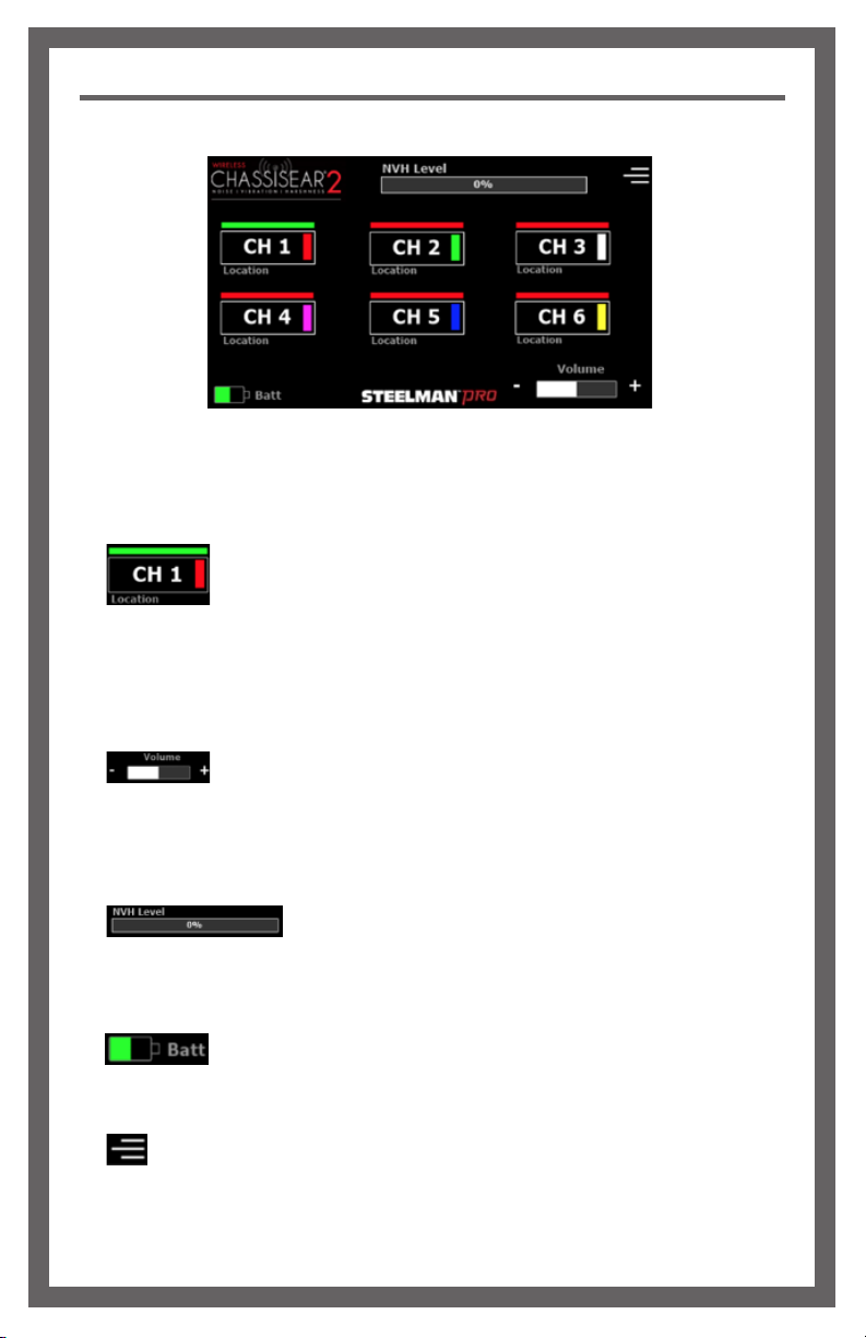
Steelman PRO Wireless ChassisEAR2 User manual

1
INSTRUCTION MANUAL 60605

2
TABLE OF CONTENTS
SAFETY INSTRUCTIONS
Safety Instructions
Overview
Main Components
Component Description
Charging
Diagnostic Use
Main Screen
Location Settings Screen
System Setting Screen
Transmitter Channel Adjustment
Accessories and Replacement Parts
Notes
NOTE: Please heed the following safety warnings and precautions:
To prevent personal injury or vehicle damage please read safety precautions and warnings
before working on vehicle.
1.) Always perform automotive testing in a safe environment.
2.) Wear eye protection that meets ANSI standards.
3.) Keep clothing, hair, hands, tools, test equipment, etc., away from all moving or hot
engine parts.
4.) Operate vehicle in a well-ventilated work area. Exhaust gases are toxic.
5.) Use blocks on drive wheels and never leave vehicle unattended while running tests.
6.) Use extreme caution when working on the ignition coil, distributor cap, ignition wires
and spark plugs. These components create hazardous voltages when the engine
is running.
NOTE: Changes or modications to this equipment not expressly approved by
JS Products will void the warranty of this product.
NOTE: It is the responsibility of the user to use only the accessories supplied with this
equipment. Use of 3rd party accessories will void the warranty.
WARNING: Cancer and Reproductive Harm. www.P65Warnings.ca.gov
2
3
4
4
5
5
6
7
8
9
10
11

3
OVERVIEW
The STEELMAN PRO™Wireless ChassisEAR2®is a versatile noise, vibration, and harshness
(NVH) diagnostic tool. The STEELMAN PRO™Wireless ChassisEAR2®Digital Control Unit
receives NVH sounds from up to six transmitters that are connected to precision piezo
microphones embedded inside of the included sensor clamps. These clamps can be
attached to almost any location on a vehicle that is experiencing elusive NVH to amplify
sounds and aid in locating NVH. The unit can be used on a vehicle either while parked or
during a road test.
Some examples of areas where NVH originates and this unit can be used are:
• Wheel Bearings
• Brake Calipers
• C.V. Joints
• Leaf and Coil Springs
• Differentials
• Transmissions
• Body Mount Points
• Interior Trim
Please read carefully the following instructions to ensure optimum use of the product.
• Fuel Injectors
• Alternators
• Water Pumps
• Power Steering Pumps
• AC Compressors
• Accessory Pulleys
• Motor Mounts
• Engine Bay

4
MAIN COMPONENTS
COMPONENT DESCRIPTION
Description Quantity
Rechargeable Control Unit 1
Rechargeable Transmitters 4
Sensor Clamps 4
Transmitter Extension Jumpers 4
Nylon Ties 6
Velcro Straps 6
Transmitter Charging Station 1
120V AC Power Adapter for Charging Station 1
Mini-USB to USB Charging Cable for Control Unit 1
Canvas Storage Bag 1
Transmitter
Charging Station Headphones
Rechargeable
Control Unit
Rechargeable
Transmitter
Sensor
Clamp

5
CHARGING
DIAGNOSTIC USE
1.) To charge the Control Unit, use the included micro USB/USB cable. Plug the small end
into the micro USB port on the left side of the Control Unit. Plug the large end into a USB/
DC converter (not included) or into a USB charging receptacle. An LED on the power
button will illuminate RED while the Control Unit is charging. The LED will illuminate
GREEN when charging is complete.
2.) To charge the Transmitters, plug the Charging Station into an AC power source. Insert
each transmitter into an available slot on the Charging Station. The Transmitter status
LED will illuminate RED while the unit is charging. When charging is complete, the LED
will illuminate GREEN and then slowly fade to OFF.
It is illegal in many jurisdictions to operate a motor vehicle while wearing
headphones. It is strongly recommended that any road testing be conducted with a
dedicated driver AND a technician.
1.) Power on the Control Unit by pressing the power button once.
2.) Power on each Transmitter by plugging them into the Sensor Clamp. The status LED
will illuminate BLUE indicating that the Transmitter is powered and active.
3.) Place the Transmitters in each location that you wish to examine for NVH.
4.) In conned spaces, the Transmitter Jumper can be used to locate the clamp and
Transmitter separately. Plug the male end of the jumper into the Sensor Clamp. Plug
the Transmitter into the female end of the jumper.
5.) Secure Transmitters using included Velcro and nylon ties to ensure they are not lost
during road testing.
CAUTION:

6
MAIN SCREEN
The Main Screen is the landing screen when Wireless ChassisEAR2®is powered on.
The use and functions of the main screen are described below:
1.) To select a channel to listen to, tap on the desired channel number
button. If the bar on top of the channel number button is green, the channel is active
and the transmitted sounds are being played back. If the bar on top is red, the channel
is inactive. The location label below the button can be set from the “Location Settings”
screen. The vertical color boxes on the right side of the channel button correspond with
the boot color on the Transmitters.
2.) The volume buttons control volume output from the control unit. Tap “-”
to decrease the volume and “+” to increase the volume. The sound from each Transmitter
can be played back through the integrated rear speaker or through the included
Headphones by plugging the headphones into the headphone port on the right side of
the control unit.
3.) The NVH Level Meter shows the signal (noise) level of the
selected channel being transmitted to the Wireless ChassisEAR2® receiver. The color
of the meter will change between green, yellow, and red based on the level of the noise
received with green being the lowest level and red being the highest.
4.) The Batt Meter shows the current Control Unit battery level. The meter will
change to YELLOW when charging is needed soon and RED when battery depletion is
imminent. The continuous run-time of the control unit is approximately 3.5 hours.
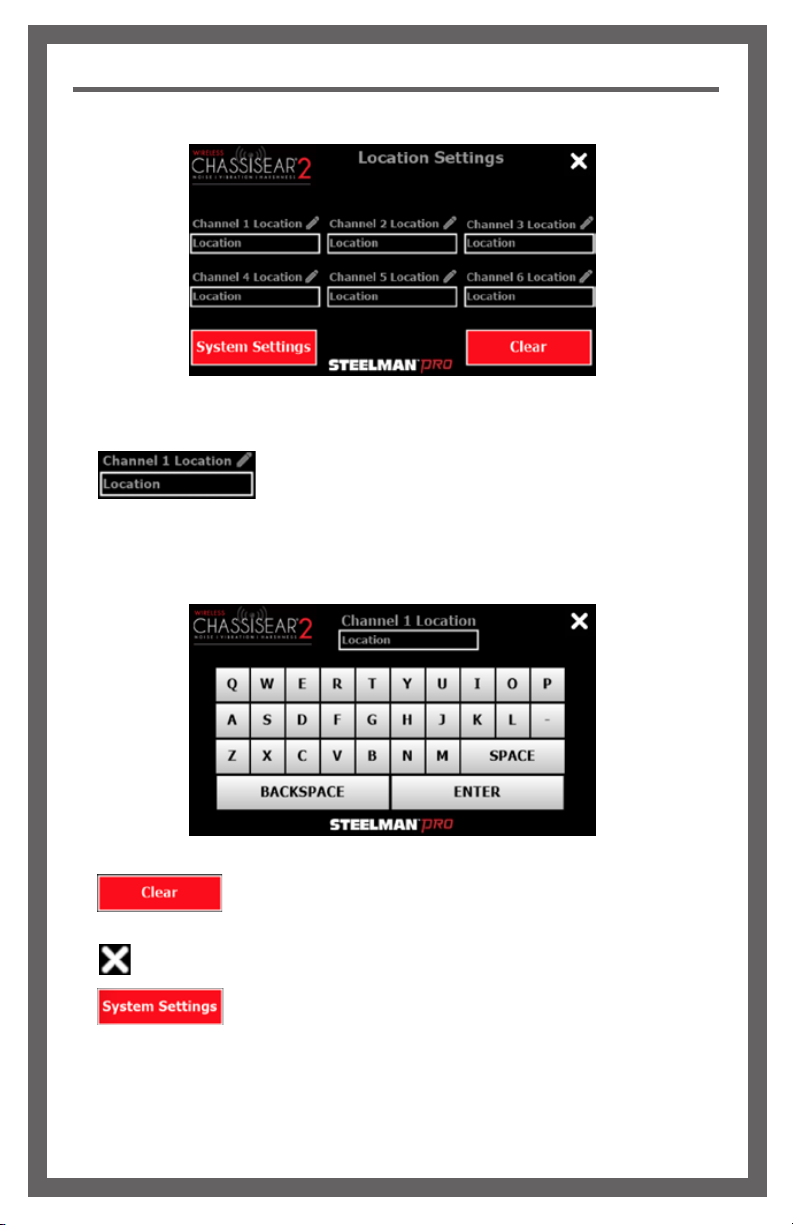
5.) The hamburger menu button will open the “Location Settings” screen where
the location for each Transmitter can be input. Additional settings and functions can be
accessed from this screen.
Main Screen

7
LOCATION SETTINGS SCREEN
1.) To edit Transmitter location information, tap the location text box
under the channel location you wish to edit. A digital keyboard will be displayed, allowing
the user to type the Transmitter’s location. Press “ENTER” to return to the Location
Settings screen.
2.) The “Clear” button clears any locations previously entered and
automatically returns to the Main Screen.
3.) The “X” button saves all changes and returns to the Main Screen.
4.) The “System Settings” button displays the System Settings screen.
Location Settings Screen

8
System Settings Screen
Main Screen with Measurements ON
1.) The “Signal Sampling Rate” box allows the user to select the speed at which the
Wireless ChassisEAR2®samples the signal strength. Default is “Fast”. A slower rate will
slow the speed at which the signal strength bar graph moves in real time.
2.) The “Measurement Type” box allows the user to display the Peak Signal Strength
measurement or Average Signal strength next to each channel on the Main Screen. The
peak signal strength setting will capture and hold the highest signal level from each
channel while it is active. Average signal strength will capture the average signal level
from each channel while it is active and then hold that value when another channel
is selected. The default setting is “Measurement Off”.
3.) “The Default Settings” button restores all settings to their default values and returns to
the Main Screen.
4.) The “X” button saves all changes and returns to the Main Screen.
5. The Peak or AVG measurement appears next to every channel, when selected on the
setting screen.
6. The Clear button resets all measurements to 0% to begin the test again.
SYSTEM SETTINGS SCREEN

9
TRANSMITTER CHANNEL ADJUSTMENT
Wireless ChassisEAR2®has six dedicated frequencies for receiving NVH noises that
correspond to a dedicated channel on the receiver. Four pre-set Transmitters are included
and up to 2 more channels can be added. The Transmitter channel can be adjusted using
the dipswitches, located behind the TPR plug on each Transmitter unit. When adding
additional Transmitters or replacing old ones, the channel will need to be set before rst use
Please see the diagram below for the dipswitch setting for each channel.
Channel 1
Channel 2
Channel 3
Channel 4
Channel 5
Channel 6

10
ACCESSORIES AND REPLACEMENT PARTS
Part Number Description Quantity
61001 Custom Screen Protector 10
60901 Wireless ChassisEAR2®Control Unit 1
60902 Sensor Clamp 1
60903 Wireless ChassisEAR2®Transmitter 1
60904 Canvas Storage Bag 1
60905 Headphones 1
60906 Color-coded Rubber Boots for Transmitters 6
90915 Velcro Straps 6
90916 Nylon Ties 6
60685 6 Port Charging Station for Transmitters 1
61002 5.5VDC @ 3.5Amps with US Adapter 1
61003 Control Unit Charging Cable 1
60028 Transmitter Jumper Cables 4
91925-03 Aluminum Probe with Rubber Tip 1
78687 Sound Wand 1
78618 USB Wall Charger 1

11
NOTES

JS PRODUCTS | 6445 MONTESSOURI STREET | LAS VEGAS, NV 89113
800.255.7011 | FAX: 775.898.8773 | WWW.STEELMANPRO.COM
ONE YEAR LIMITED WARRANTY
is product is backed by a one year l im ited wa rra nty. is
warranty covers manufacturer defects and workmanship. e
warranty excludes misuse or abuse and normal wear and tear.
This device complies with Part 15 of the FCC Rules. Operation is subject
to the following two conditions: (1) this device may not cause harmful
interference, and (2) this device must accept any interference received,
including interference that may cause undesired operation.
This device complies with Industry Canada
license-exempt RSS standard(s). Operation is
subject to the following two conditions:
1.) This device may not cause interference, and
2.) This device must accept any interference,
including interference that may cause
undesired operation of the device.
Le présent appareil est conforme aux CNR
d’Industrie Canada applicables aux appareils
radio exempts de licence. L’exploitation est
autorisée aux deux conditions suivantes:
1.) l’appareil ne doit pas produire de brouillage, et
2.) l’utilisateur de l’appareil doit accepter tout
brouillage radioélectrique subi, même si le
brouillage est susceptible d’en compromettre
le fonctionnement.
FCC ID: 2AR6X-60605
IC: 24657-60605
When charging the product, the transmitter needs to be placed in the charging base, and the wireless
function cannot be used normally. You need to wait until the charging is complete before you can use the
wireless function.
#15.105 INFORMATION TO THE USER
NOTE:
This equipment has been tested and found to comply with the limits for a Class B digital device, pursuant to
part 15 of the FCC Rules. These limits are designed to provide reasonable protection against harmful
interference in a residential installation. This equipment generates uses and can radiate radio frequency
energy and, if not installed and used in accordance with the instructions, may cause harmful interference
to radio communications. However, there is no guarantee that interference will not occur in a particular
installation. If this equipment does cause harmful interference to radio or television reception, which can be
determined by turning the equipment off and on, the user is encouraged to try to correct the interference by
one or more of the following measures:
• Reorient or relocate the receiving antenna.
• Increase the separation between the equipment and receiver.
• Connect the equipment into an outlet on a circuit different from that to which the receiver is connected.
• Consult the dealer or an experienced radio/TV technician for help.
This manual suits for next models
1
Table of contents
Other Steelman Tools manuals
Popular Tools manuals by other brands

DeWalt
DeWalt DS max D25701 instruction manual

FITOK
FITOK HPT-DF instruction manual

Beta
Beta 599DGT-A/10 Instructions for use

UE Systems
UE Systems GREASE CADDY ULTRAPROBE 201 VISUAL INSTRUCTIONS

Ryobi
Ryobi A18MS01 Manual del operador

Harbor Freight Tools
Harbor Freight Tools Central Machinery 46725 Assembly and operating instructions