Steenbeck 01 Series User manual
V01-2013
Copyright
©
1978 – 2013.
Steenbeck is a trademark.
No part of this manual may be reproduced without the prior written permission of Steenbeck.
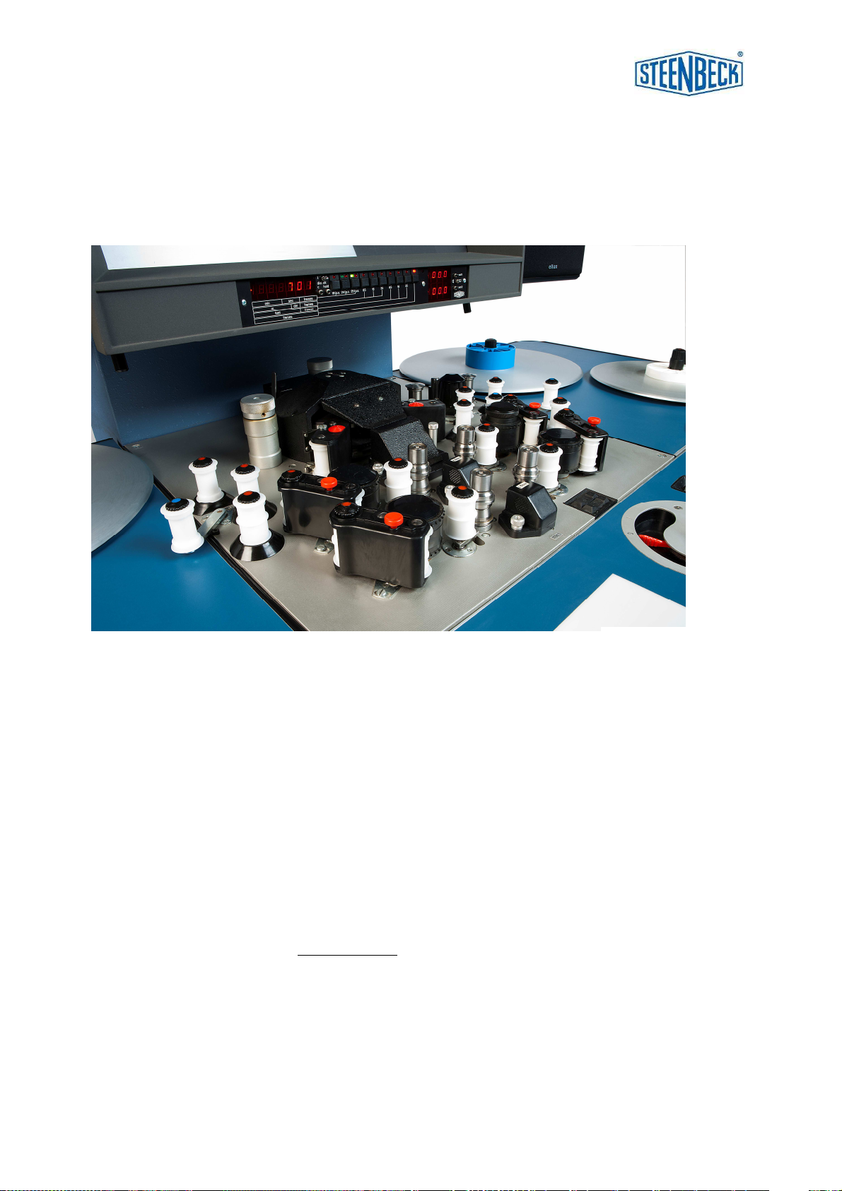
Specifications, colours etc. are subject to change without notice. Images are an example.
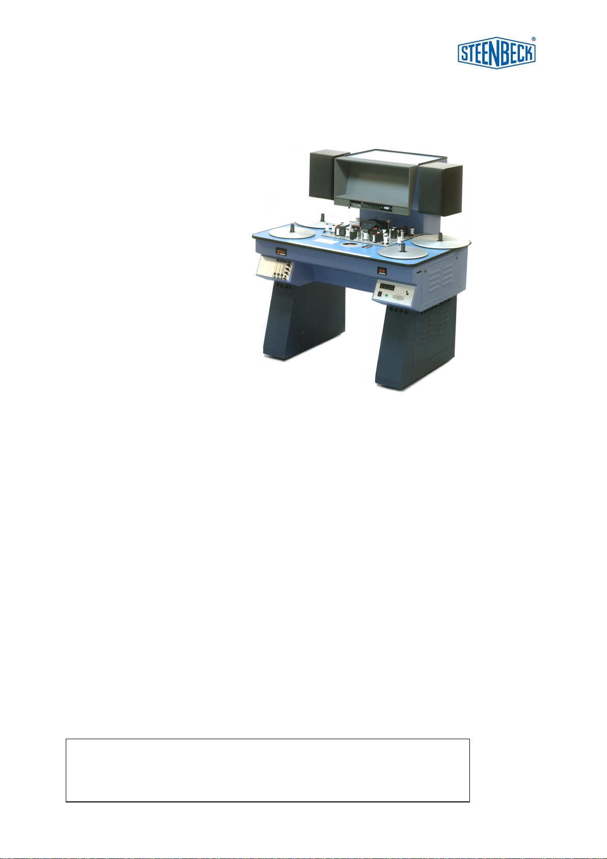
STEENBECK USER MANUAL 35mm 01-SERIES
Compact sized flatbed editors:
ST3511 2 plate, COMOPT sound.
for 600 meters / 2000 feet of film.
ST1401 4 plate, COMOPT and 1 track SEPMAG sound.
for 600 meter / 2000 feet of film and perforated tape.
ST401 4 plate, COMOPT and 1 track SEPMAG sound.
for 600 meter / 2000 feet of film and perforated tape.
picture-sound shift system for 1 track.
Larger sized flatbed editors:
ST701 6 plate, COMOPT and 2 tracks SEPMAG sound.
for 600 meter / 2000 feet of film and perforated tape.
picture-sound shift system for 2 tracks.
ST721 6 or 8, plate version with 2 picture system.
standard with one COMOPT and 2 tracks SEPMAG sound.
depending on version from 350 meter / 1200 feet up to
600 meter / 2000 feet of film and perforated tape.
picture-sound shift system for 2 tracks.
8 plate version can have 4 plates of 600 meter/2000 feet.

V01-2013 35mm-01 serie
1
Table of contents user manual:
Section
page
0.0 Table of contents 1-2
1.0 Introduction 3
2.0 General data 3
3.0 Technical data :
3.1.1. introduction 4
3.1.2. film plates / film reels / cores 4
3.1.3 shrunken material 4
3.1.4 frictions 4
3.2 picture 5
3.3 sound 5
3.4 general technical information 6
4.0 Important safety and warranty information 4.1 safety 7
4.2 warranty 8
fig. 1 general overview 9
fig. 2 switch board 10
fig. 3 sound preamplifier section 10
fig. 4 fuse panel 10
fig. 5 drive deck overview 11
5.0 How to use the 35mm 01-Series:
5.1 general overview 12
5.2 switch board and pressure switches 12
5.3 sound preamplifier section 12
5.4 drive deck 13
5.5 fuse panel 13
5.6 connecting to mains power 14
5.7 threading film and sound tape 14
5.8 rewind 15
5.9 sound 15
6.0 Universal counter /display 16
Picture - sound shift system (ST401-ST701-ST721 only) 17

V01-2013 35mm-01 serie
2
7.0 Connection loudspeakers and (optional) working lamp 18
8.0 Maintenance instructions :8.1 introduction 19
8.2 replacing picture lamp 20
8.3 replacing exciter/optical lamp 20
8.4 adjustment pressure arms picture 20
8.5 surface-coated mirrors 20
8.6 polygon and lens 20
8.7 screen 21
8.8 illumination system 21
8.9 frictions 21-22
8.10 general maintenance 22
8.11 adjustment guide ring 16mm 23
9.0 List op slow and fast moving spare parts 35mm 01-Series 24
10.0 Operation field table top: 10.1 ST3511 25
10.2 ST401 ST1401 26
10.2 ST701 27
10.3 ST721 28
11.0 Adjustment picture lamp 35mm (all models) 29
12.0 Threading film and perforated magnetic sound (MAG) tape
ST3511 picture only 30
picture with COMOPT sound 30
ST401 / 1401 picture w/o sound /w MAG sound 31
picture w sound 31
picture w COMMAG 32
ST701 picture with COMOPT sound 33
picture w/o sound / w MAG sound 33
ST721 picture with COMOPT sound 34
picture L w sound / w MAG sound 34
pictures ST701 and ST721 35

V01-2013 35mm-01 serie
3
1.0 INTRODUCTION:
The 35mm 01-Series film editing, viewing and controlling tables, is for many years a
solid proven concept for film archives, film laboratories etc..
Working with this table is comfortable. With a minimum of physical effort the film can
be checked in a fast and accurate manner, the metadata is noted and the film is
prepared for possible scanning.
This manual shows the way to use all the possibilities of this 35mm 01-Series film
table.
Caution: since the introduction of the 01 series many electronically / mechanically
developments and improvements have been made. Be aware that the type number
never have been changed since and therefor new and/or old parts/electronics not
always been interchangeable.
2.0 GENERAL DATA:
- for 35mm film, with COMOPT (optical) sound.
- 2 plate version up to 8 plate with SEPMAG sound.
- fast and accurate checking / viewing film.
- halogen lamp 12 Volt / 100 watt.
- high quality projection screen.
- digital processor counter.
- display for actual speed of the film (optional)
- Sound system:
- each preamp with fader
- summing amp.: with treble, bass and master volume potential meter
- ¼” head phone jack
- two way high quality speakers.
- switchable sync speeds 24 and 25 f.p.s. (frames per second)
- variable speed from 0 till 100 f.p.s. (approx.) (option ST200)
- standard for film cores.
- ground glass, back illuminated.
- dimmer for working lamp (option ST57).
- operating voltage selectable 100 – 240 Volt / 50 of 60Hz at 6 /10 Amp

V01-2013 35mm-01 serie
4
3.0 TECHNICAL DATA:
3.1 DRIVE SYSTEM.
3.1.1 Introduction:
The Steenbeck 01-Series has a proven 1 motor drive technology.
The table runs smoothly, because of the famous Steenbeck ‘speed switch’.
This speed switch has fixed points for sync (synchronous 24 of 25 frames per second
f.p.s.) forward and reverse, and adjustable notches between sync en maximum
speed. (approx. 50 f.p.s., forward and reverse selectable by user).
The maximum speed can also be adjusted to approx. 100 f.p.s.
The maximum for both directions can be a little different.
3.1.2 Film plates / cores:
Depending on version the film plates are for approx. 400 meter / 1300 feet of film up
to 600 meter / 2000 feet of film with cores/bobbins according to DIN 15531.
The winding tension of the plates can be adjusted.
3.1.3 Shrunken material:
The standard supplied sprocket rings are made to be used also for slightly shrunken
film material. If the film is in a bad condition (very stretched or shrunken) it is
advisable to change the sprocket ring at the polygon, otherwise the film can be
damaged.
For shrunken film with sound the COMOPT sprocket should also replaced by a
shrunken one.
We also have sprockets for shrunken SEPMAG perforated tape.
See options for the correct stock numbers in case of ordering.
3.1.4 Frictions:
The frictions are fitted with core holders for use of film cores.
It is recommended to use film bobbins/cores of 100mm diameter.

V01-2013 35mm-01 serie
5
3.2 PICTURE.
The rear screen projection method via an optical compensation system is done with
18-face revolving prism (polygon). With the high quality surface mirrors, optics and
screen material gives this a very brilliant, bright and sharp image.
The standard dimensions of the projection are 212 x 288 mm.
Accurate film transport is achieved by revolving sprockets .
The picture lamp can easily be replaced and adjusted.
In stand-still mode the light is automatically dimmed to prevent heat damages to the
film. The easy threading of film and perforated tape saves time and protect the film
from being damaged. (see pages 29 - 32 )
Option ST92: Cinemascope
3.3 SOUND.
High quality sound reproduction is done by plug-in pre-amplifiers.
All sound is mono, however stereo SEPMAG is optional available.
COMMAG sound mono is optional available.
ST3511: COMOPT, mono
ST(1)401: COMOPT, mono 1 track of SEPMAG (mono)
ST701 COMOPT, mono 2 track of SEPMAG (mono)
ST721: 1x COMOPT, mono 2 track of SEPMAG (mono)
-summing amplifier with: treble / bass / master volume adjust.
head phone output with ¼” jack.
-2 loudspeakers 2 way, 2 x 30 watt.
The so called synchronize points for film and PE sound film (perforated tape) are
only available on request as an option.

V01-2013 35mm-01 serie
6
3.4 GENERAL DATA.
Power: 1 phase 100 – 240 Volts - 50 / 60 Hz.
Power consumption: approx. 800 – 1000 W. (depending on version)
Switch on current: 10 Amps. (at 230 V)
The fuses (5x20mm) 100 – 120 Volt 10 Amp T and 0,5 Amp T.
220 – 240 Volt 6,3 Amp T and 0,5 Amps T
The fuses can be found on the back side of the machine. (see fig. 4 page 10)
Important: all fuses in the Steenbeck 01-Series are T(slow blown) and
Should never be replaced by F (fast blown) fuses.
Sizes of a complete table incl. monitor and speakers:
ST3511 – ST(1)401; compact sized editors:
width 120 cm
working height 80 cm
depth, incl. monitor 99 cm
total height 129 cm
Weight 150 kg up to 160 kg.
ST701 – ST721; large sized editors:
width 152 cm
working height 80 cm
depth, incl. monitor 109 cm
total height 129 cm
Weight 200 kg up to 230 kg.

V01-2013 35mm-01 serie
7
4.0 IMPORTANT SAFETY AND WARRANTY INFORMATION.
4.1 SAFETY:
The installation and maintenance should always be done by Steenbeck factory
engineers or an appointed /certified Steenbeck agent / dealer.
Of highest importance is a well-connected and safe power ground system.
This system has to be in a 100% condition, because of:
- the safety of the user of the Steenbeck 01-Series
- the risk of electronically malfunction both inside and outside the table.
- discharge of static electricity.
The 01-Series should always be placed in a dry room and free from dust.
The temperature should be between 5° C and 40° C (40°F 105°F)
Humidity should be between 30% to 70% (approx.).
A higher humidity can cause corrosion on electronic contacts.
Warning: never put drinks / liquids on the Steenbeck machine.
Liquid spill, when leaking into the machine, can cause great damage and can be
dangerous for its user.
Regularly clean the machine with the brush and the special cleaning wipes (blue is
for wet use and yellow is for dry cleaning). Never use steel cleaning tools.
Never open the machine.
If there is any mechanical or electronically alignment needed, these should be done
by a Steenbeck engineer or by Steenbeck trained staff.
It’s advised to use good trained staff to work with the Steenbeck machine.
It’s very important that this personnel has read and studied the user manual.
IMPORTANT:
There is always a personal danger related to the revolving sprockets.
Beware of this danger when having long hair, necklaces, bracelets,
long sleeves etc.

V01-2013 35mm-01 serie
8
4.2 WARRANTY INFORMATION:
STEENBECK film machines are made with the best possible accuracy and precision.
Extensive runs and tests are done on the machine prior to shipment.
STEENBECK film machines are built to achieve maximum quality, reliability, and long
life resulting in a minimum of maintenance.
There is always the possibility that within the warranty period of 1 (one) year,
after purchasing the Steenbeck, a part is not working properly.
In such case, please contact the Steenbeck factory or your local Steenbeck
agent/dealer at once.
Defective parts will be repaired or replaced by Steenbeck.
Before replacing the part, Steenbeck has the right to check the part before
replacing it.
No warranty in case of:
- the machine is used for a different purpose than what it was made for.
- deliberate damage.
- an untrained technician has worked at the machine.
- defective projection or optical sound lamp, wire breakage.
- damage the lacquer by use, bumping or cleaning with not advised solvent.
Defective parts should be send to the Steenbeck factory in Holland or the local
agent/dealer at cost and risk of the owner/user of the Steenbeck machine.
The costs for the repair or replacement of parts are in principle always
at cost of Steenbeck.
The Steenbeck factory always returns the parts free of charge. The replaced parts
are always property of Steenbeck .
If a Steenbeck engineer is required to take care of the warranty repairs or
replacements, all travelling and accommodation costs are for the owner/user of the
Steenbeck machine.
V01-2013 35mm-01 serie
9
7
10
5
6
4
9
10
3
1
11
8
2
fig.1
V01-2013 35mm-01 serie
10
16 17 18 19
14 15
20
2122
fig. 2
fig.3
25 26
28
2930
27
fig.4
58
61
60
56
56
57
59
V01-2013 35mm-01 serie
11
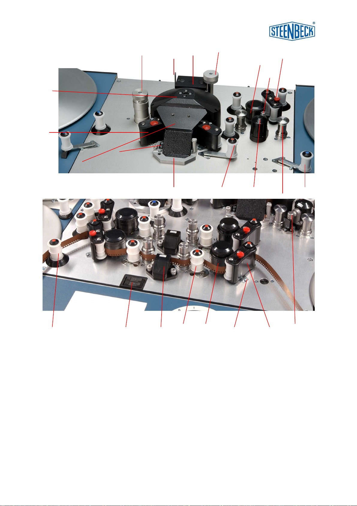
5.4 DRIVE DECK OVERVIEW (fig. 5)
34. polygon cover cap (support guide ring; not on photo) 51. switch for sound-shift system. ST401-701-721 only
35. pressure arm picture left and right 52. lens and prism system
36. pressure arm sound left and right 53. screw bearing shaft plate pressure arm
37. COMOPT sprocket for film with sound 54. SEPMAG / SEPOPT sprocket
38. push button (red) to detach pressure arm 55. interchangeable condensor system
39. cover plate (lift when threating film) (part of the illumination system)
40. switcher between standard image and Cinemascope
41. focus image
42. guide rollers film
43. optical sound reader COMOPT
44. knob for framing by hand. (don’t touch it while running)
45. tension roller; a) for film with sound b) for SEPMAG sound
46. protection cap optical sound lamp (OPT. 2)
47. fly wheels to optimize sound
48. hexagon screws for adjusting picture lamp (see also page 28)
49. tension arm
50. magnetic head for SEPMAG (or placing SEPOPT / OPT. 1)
3642 435051 535445
34
35
37 38
39
4041
43
4645 47
48
49
52
55
44
fig 5

V01-2013 35mm-01 serie
12
5.0 HOW TO USE THE STEENBECK 35mm 01 - SERIES:
Read this section carefully, study all the possibilities and run some tests.
Make the most important actions your own.
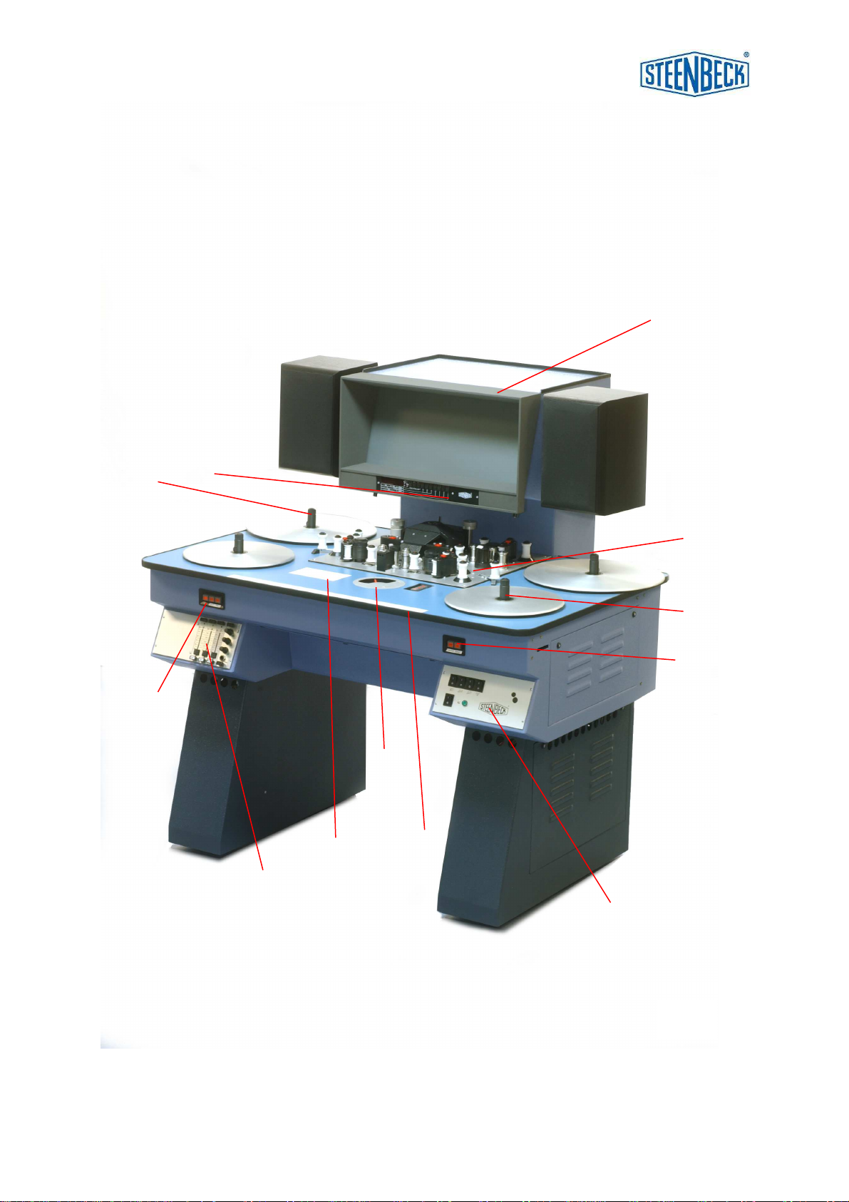
5.1 GENERAL OVERVIEW: (fig. 1 page 9)
1 drive deck
2friction left
3friction right
4ruler
5ground glass (back lit), to check film
6speed switch
7sound preamplifier section
8universal counter /display (fig. 15)
9switch board
10 pressure switches
11 screen holder
12 -
13 -
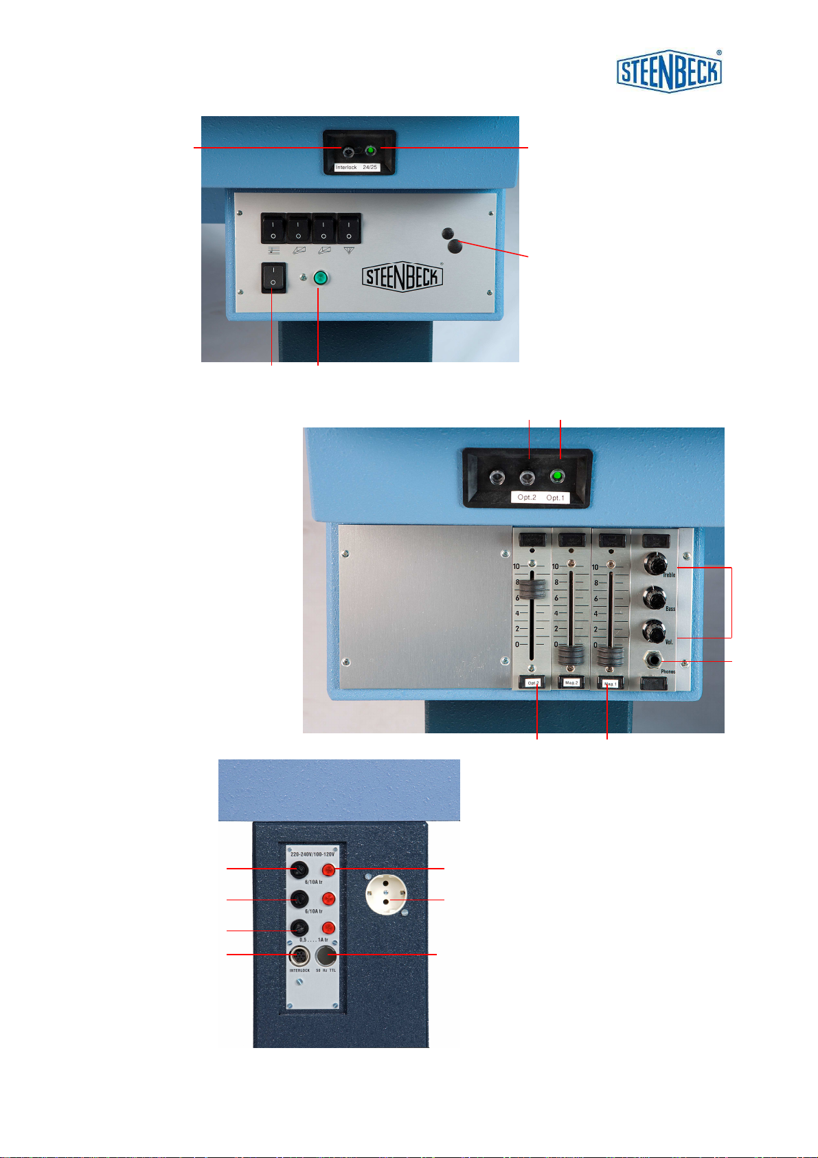
5.2 SWITCH BOARD and PRESSURE SWITCHES: (fig. 2 page 10)
Switches 16 t/m 19 are the so-called sub functions.
14 main power on / off switch
15 pilot lamp
16 on / off switch sound
17 on / off switch picture lamp
18 on / off switch 2
nd
picture lamp (ST721 only) or switch video lamp
19 on / off switch back light ground glass
20 rotary knob for dimmer working lamp (optional)
21 pressure switch for synchronous speed 24 or 25 f.p.s.
The selected speed is indicated by a green LED on the counter display
22 interlock: not in use since 2010
23 -
24 -
5.3 SOUND PREAMPLIFIER SECTION (fig. 3 page 10)
25 pressure switch for optical sound lamp (OPT. 2)
26 pressure switch for 2
nd
optical lamp (SEPOPT – OPT. 1)
27 summing amplifier, with treble, bass and master volume control
28 headphone ¼” jack (mono)
Don’t use a head phone with less than 600 Ohm impedance
29 magnetic preamplifier
30 optical preamplifier
31 -
32 -
33 -

V01-2013 35mm-01 serie
13
HOW TO USE THE STEENBECK 35mm 01-SERIES. (continued)
5.4 DRIVE DECK OVERVIEW ( 2 figures) (fig. 5 page 11)
34 polygon cover cap (support guide ring; not on photo)
35 pressure arm picture left and right
36 pressure arm sound left and right
37 COMOPT sprocket for film with sound
38 push button (red) to detach pressure arm
39 cover plate (lift when threating film)
40 switching between standard image and Cinemascope
41 focus image
42 guide rollers film
43 optical sound reader COMOPT
44 knob for framing by hand. (don’t touch it while running)
For accurate framing it is advisable to operate the editor at a low
speed and employ push button ‘framing’.
45 tension roller; a) for film with sound b) for SEPMAG sound
46 protection cap optical sound lamp (OPT. 2)
47 fly wheels to optimize sound
48 hexagon screws for adjusting picture lamp (see also page 28)
49 tension arm
50 magnetic head for SEPMAG (or placing SEPOPT / OPT. 1)
51 switch for sound-shift system. ST401 - ST701 – ST721 only.
52 lens and prism system
53 screw bearing shaft plate pressure arm (see also page 23)
54 SEPMAG / SEPOPT sprocket
55 interchangeable condensor system (part of the illumination system)
(see also fig. 12 page 29 )
5.5 FUSE PANEL: at the back of the right hand leg (fig. 4 page 10)
56 fuse 6,3 Amps T (220 / 240 volts) or 10 Amps T (110 / 120 volts)
57 fuse 0,5 Amps T for all voltages or 1 Amp T (110 / 120 volts)
58 pilot lamp fuses. (on when a fuses is blown)
59 Interlock (not in use with 01-Series, from 2010 onwards)
60 bi-phase (not in use with 01-Series, from 2010 onwards)
The fuses are located in a holder with bayonet mount.
If a fuse has blown, the pilot lamp (39 page 10) next tot his fuse will be on.

V01-2013 35mm-01 serie
14
HOW TO USE THE STEENBECK 35mm 01-SERIES. (continued)
5.6 connecting to mains power:
Connect the machine to the power network according to the instructions on page 5
with the supplied power cable. Make sure that this cable is well connected.
Always check the Voltage and Frequency mentioned on the type and serial number
plate (back side table).
Of great importance is a safe power ground system.
Switch the 01-Series on with the main switch fig.2 #14 page 10), it shows a green
light.(15)
Only then switch on the sub functions (from 16 onwards).
Warning : before switching off the table, always switch off all the sub functions.
5.7 Threading film:
Thread 35mm film according to pages 30 - 34
Attention: in order to prevent unnecessary wear, when threading film without sound,
never use the magnetic head (fig. 5 #50 page 11) and sprocket (37), and switch off
the sound (fig. 2 #16 page 10).
When the film has COMOPT sound, thread the film with sprocket (37) in a way the
tension roller (45) can move a little bit, this because too much tension can damage
the perforation.
Use the speed switch (fig 1 #6 page 9) to view the film.
While winding or rewinding from 0 to sync speed and sync, the speed is continuously
variable.
This makes it possible to view the film frame by frame.
When the framing is not correct it can be adjusted (see pages 25 - 28).
Focus picture is adjustable (fig.5 #41 page 11).
Thread the 35mm film according the version.
Pages 30 - 34 show the way to thread film with and without sound.
Also shown are the threading of SEPMAG / SEPOPT.

V01-2013 35mm-01 serie
15
HOW TO USE THE STEENBECK 35mm 01-SERIES. (continued)
5.8 Rewind:
Don’t rewind the film as it is thread for viewing, because of the sprockets, older films
with bad splices and perforation can get damaged.
It’s advised to rewind the film always with a (Steenbeck) film rewinder.
The Steenbeck film rewinder can wind forward and backward and the speed can be
adjusted, even to very slow. This can be useful when it’s required to check or clean
the film by hand.
5.9 Sound:
The 35mm film can be viewed with optical (COMOPT) sound
and separate magnetic sound (SEPMAG).
See for threading film with COMOPT sound and SEPMAG sound pages 30-34.
Hints for optical sound:
-if optical is unused, it’s preamplifier fader should be set to zero position.
-avoid direct exposure of the optical sound reader by room light or table working
lamp. The light sensitive device in the sound reader may be influenced by this
exposure and causing extra audible noise like hum.
Adjustment of the volume with the fader halfway on the preamp first.
(page 10 #29 – 30)
Then the master volume control button (page 10 #27) in the mid .
Adjustment of the sound by treble and bass (page 10 #27)
Plug in a headphone with a ‘1/4”jack’ (page 10 #28).
When a headphone is used, the speakers are off.
Caution:
When the level of the headphone is to low, it’s caused by the impedance of the
headphone

V01-2013 35mm-01 serie
16
10 1
6.0 Universal counter:
For ST3511 – ST(1)401 – ST701 – 2
nd
counter ST721.
The Steenbeck universal counter is designed to measure film length (all formats) and
calculate the position and time information in common use.
Additionally, the universal counter may offer extra possibilities for more effective work
on your film rewind / film inspection table.
The counter / calculator functions are controlled by keys No. 1 – 10 (right to left)
1. frames counts and displays number of frames (max. 1.999.999)
2. feet 35mm displays film length in feet (16 frames = 1 foot)
3. feet 16mm displays film length in feet (40 frames = 1 foot)
4. feet 8Smm displays film length in feet (72 frames = 1 foot)
5. m / dm 35mm displays film length in meters (1 meter = 52,630 frames)
6. m / dm 16mm displays film length in meters (1 meter = 131,200 frames)
7. m / dm 8Smm displays film length in meters (1 meter = 236,200 frames)
8. min / sec 25 FPS displays elapsed time (1 second = 25 frames)
9. min / sec 24 FPS displays elapsed time (1 second = 24 frames)
10. min / sec 18 FPS displays elapsed time (1 second = 18 frames)
The two digits to the right always indicate numbers of frames.
The other digits show the counter value according to the chosen film format.
A red LED on the key indicates the activated display format.
The green LED indicates 24 or 25 frames per second sync speed of the editor.
Together with the keys you will find one switch and two pushbuttons on the counter
front panel.
Pushbutton C = Clear Counter is reset to ZERO.
Pushbutton HOLD Display is stopped at actual reading.
The counter keeps on counting. When releasing
Pushbutton , counter value is transferred to display.
Switch DIST CTR Setting 1: distance counter on
Setting 0: distance counter off.
The distance counter is activated to measure partical
length or time values.
It can be reset to ZERO (C)
without effecting the main counter.

V01-2013 35mm-01 serie
17
B
D
C
A
D
UNIVERSAL COUNTER PICTURE – SOUND SHIFT SYSTEM.
For ST401 – ST701 – ST721
The picture-sound synchronizer shows the shift of the sound tape
against the picture tape in positive and negative directions.
The range of display is ± 99.9 frames.
The shift of the sound tape is accurate tot 1/100 of a frame –
displaying are 1/10 of a frame.
A switch Amakes two type of operation possible:
Switch position B:
As long as the switch 51 (fig. 5 page 11) is pushed the picture – sound shift runs
continuously and can be stopped at any desired point.
Thus both tapes can (with a ST701-ST721) be brought together with perforation
correct at the sync point.
For ST401 one display is in function.
Switch position C:
With every touch of the switch 51 the sound tape be moved forward or backward by
exactly one frame, e.g.: to bring forward the sound by ten frames, the switch in a
forward position has to be momentarily pressed ten times.
By prolonged pressing the tape will carry on till the key is released.
The tape will now exactly to a perforation.
This will avoid the troublesome forward and backward pulling of the tape to
synchronize the two.
Push buttons D: reset display.
V01-2013 35mm-01 serie
18
7.0 Connecting loudspeakers and (optional) working lamp:
All connections at the back of the frame.
Work light: (fig. )
Connector for 230V light max. 60 Watt.
The connection is as follows:
230 Volt: pin 1 = phase + / pin 2 = phase - / pin 3 = ground
ST701

V01-2013 35mm-01 serie
19
8.0 MAINTENANCE INSTRUCTIONS.
With the 01-Series delivered tools and spare parts which also can
be ordered separately:
part number:
Tools:
1 x wrench M2,5 to adjust frictions 9962.0088.00
1 x hexagon M4 to adjust picture lamp 9962.0087.00
Cleaning brush N000.0473.00
Cleaning cloths set ( blue and yellow) N000.0521.00
Spare parts:
2 x picture lamp 12V- 100W 9956.1066.00
1 x exciter/optical sound lamp 9956.1080.00
10 x fuse 6,3 Amp. T (5 x 20 mm) 9956.0232.00
10 x fuse 0,5 Amp. T (5 x 20 mm) 9956.0224.00
Various:
Dust cover 9962.1083.00
8.1 Introduction.
The Steenbeck 01-Series doesn’t need much maintenance. It depends on by whom,
how and under what circumstances the table is used. It’s advised to clean the table
every time it has been used with the supplied brush.
Clean the top of the table with the supplied cloth; Start cleaning with a moist
microfiber cloth (Blue) and dry it with the (Yellow ) dry cloth.
Caution: technical maintenance.
When the Steenbeck 01-Series is regularly in use (almost daily basis and more) the
maintenance needs to be done at least once a year by the dealer or Steenbeck
factory engineer. In this service the table will remain in a good condition.
To facilitate the operation the following instructions should be strictly adhered
to. (pages 19 – 23)
= only done by skilled staff
Before opening the machine be sure it is disconnected from the mains.
Only service engineers are authorized to do adjustment and technical maintenance.
The machine should only be operated with the side and front panels closed.
This manual suits for next models
5
Table of contents
Popular Laboratory Equipment manuals by other brands


ITW
ITW Foster Control Thaw CT75 Operation instructions

Miele
Miele E 941/1 instructions

Socket
Socket DURASCAN D840 Series Programming guide

Teledyne
Teledyne ASX-560 Quick installation guide

Agilent Technologies
Agilent Technologies SureCycler 8800 Setup and user guide

Fritsch
Fritsch PULVERISETTE 7 classic line operating manual


