Stefan Mayer Instruments MR-3 User manual

Stefan Mayer Instruments
MR-3
Triaxial Magnetic Field
Compensation System
User’s Manual
– April 2023 –
Stefan Mayer Instruments GmbH & Co. KG
Hans-B¨ockler-Str. 21c, D-46535 Dinslaken, Germany
Tel./Fax: +49 2064 479762/3

Contents
1 Safety precautions 2
2 Introduction 3
3 What’s new? 4
4 Operation 5
4.1 Sensorinstallation ........................... 5
4.2 Instrument installation . . . . . . . . . . . . . . . . . . . . . . . . . 5
4.3 Frontpanelsummary.......................... 5
4.3.1 Sensormodule.......................... 6
4.3.2 Auto-offset module . . . . . . . . . . . . . . . . . . . . . . . 6
4.3.3 Field monitor module . . . . . . . . . . . . . . . . . . . . . . 7
4.3.4 Controller module . . . . . . . . . . . . . . . . . . . . . . . . 8
4.4 Rearpanelsummary .......................... 9
4.5 Electrical connections . . . . . . . . . . . . . . . . . . . . . . . . . . 10
4.6 Power-up ................................ 10
4.7 Operation of the controllers . . . . . . . . . . . . . . . . . . . . . . 11
4.8 Adjustment of the PI controllers . . . . . . . . . . . . . . . . . . . . 12
5 Alarm function 13
6 Maintenance 13
7 Specifications 14
8 Conversion of Measurement Units 15
9 Warranty 16
1

1 Safety precautions
The following safety precautions should be observed before using this
instrument:
This product is intended for use by qualified personnel who are familiar
with the safety precautions required to avoid possible injury.
Read the operating information carefully before using the instrument.
The instrument must not be operated in explosive atmosphere.
The instrument should only be used in dry rooms.
The operation of the instrument is left at user’s risk.
The instrument must be placed in such a way that it can be easily
disconnected from the power line by unplugging the mains plug.
The ventilation slots and heat sinks must not be covered. Provide suf-
ficient air flow for cooling. In critical cases an air fan should be used.
The heat sink mounted on the instrument’s rear side can be-
come hot during operation. Therefore it is marked with this
warning symbol:
Before operating the instrument, make sure the power cord is connected
to a properly grounded power receptacle.
Before performing any maintenance, disconnect the power cord.
The detachable power cord must not be replaced with lower rating
types. See chapter ”Specifications” for power cord ratings.
Replace blown fuses with same type and rating for continued protection
against fire hazard.
Do not exceed the electrical and thermal operating limits, as defined
in the specifications section. Disregard can cause destruction of the
instrument and consequential damages.
If the instrument is used in a manner not specified by the manufacturer,
the protection provided by the instrument can be impaired.
Stefan Mayer Instruments shall not be liable for any direct, indirect,
special, incidental or consequential damages arising out of the use of its
instruments.
The instrument and this manual may be subject to alterations without prior notice.
2

2 Introduction
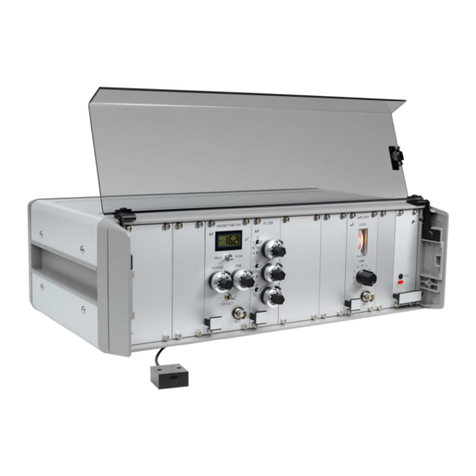
Fig. 1: Magnetic Field Compensation System MR-3
The magnetic field compensation system MR-3 has been designed for automatic
triaxial compensation of magnetic field disturbances in the frequency range from 0
to >500 Hz. The system reduces slow disturbances, e. g. caused by trams, elevators
or vehicles, as well as magnetic noise produced by power lines (typ. 16.7 Hz,
50 Hz, 60 Hz, and harmonics) by establishing a compensation field with the help
of suitable compensation coils. The typical attenuation of a 50 Hz magnetic field
is 40 dB at the sensor location. Very slow disturbances with a frequency up to
a few Hertz are practically eliminated down to the noise level of the magnetic
field sensors of <1 nT. The actual frequency response of the system depends on
the parameter of the connected compensation coils, the adjustment of the control
electronics, and the homogeneity of the magnetic field.
The magnetic field deviations from the preset values are measured in three dimen-
sions (X, Y, and Z) with highly sensitive fluxgate magnetometers.
3

Analog PI controllers control built-in power current sources which drive a suitable
set of Helmholtz-type coils. The coils generate a compensation field which reduces
the original field disturbances. The compensation coils are not part of the MR-3
system and must be provided by the user or service partner. Contact Stefan Mayer
Instruments for a proposal for suitable compensation coils.
3 What’s new?
The system described in this manual provides additional features in comparison
to preceding versions. The most important modifications and features are the
following:
a. Low emission switching power supply with high efficiency and wide input range
for worldwide use.
b. Reduced weight and size.
c. Magnetic field monitoring module with digital displays for incremental DC and
true RMS AC magnetic field, adjustable trip levels and alarm function.
d. Selection between DC, AC+DC, and AC controller mode. In AC mode the
system only compensates AC magnetic field with a frequency above 10 Hz. This
is useful to simplify the operation where only AC compensation is required.
e. Automatic offset control. The field settings are automatically adjusted to
proper values by just pressing a single push-button. In AUTO mode the system
automatically recovers from overload by auto-adjusting the field settings to new
values. This assures proper operation after heavy changes of the DC magnetic
field conditions.
4

4 Operation
4.1 Sensor installation
The triaxial magnetic field sensor should be fixed in the center of the compensation
coil system. Two M4-threads are provided at the front face of the sensor for
mounting with plastic screws. All parts of the sensor mounting must be totally non-
magnetic. Plastic parts are recommended. Stainless steel or brass are sometimes
magnetic. At the front face, the sensor has an edge parallel to the X-direction which
simplifies alignment of the sensor and coil axes. The measurement directions of
the sensor are shown in figure 2.
Fig. 2: Definition of sensor measurement axes
4.2 Instrument installation
The MR-3 system can be used as bench-top instrument or can be mounted in 19-
inch racks. In any case, there must be sufficient air flow through the instrument
and the fins of the heat sinks for cooling. Never cover the ventilation slots of the
lid, bottom, and side panels nor the heat sink at the rear side. If necessary use
air fans to provide enough air convection. Never install the instrument in closed
cabinets without fan cooling.
4.3 Front panel summary
The front panel of the MR-3 system contains individual modules which are de-
scribed in the following sections.
5

4.3.1 Sensor module
Fig. 3: Sensor module
The sensor module carries the drive and detection electronics of the triaxial flux-
gate magnetic field sensor. The magnetic field components X, Y, and Z are con-
verted to proportional voltage signals which are present at the BNC connectors
(1) in figure 3 on the module front. The bandwidth of the signals is DC to 1 kHz.
The scale factor is 1 V/µT in the output range between −6 V and +6 V. The
output terminals can be used to monitor the magnetic field components with an
oscilloscope or chart recorder. Any instrument connected to the analog outputs
must have an input impedance of more than 5 kΩ. The outer contacts of the
output BNC connectors are grounded.
4.3.2 Auto-offset module
Fig. 4: Auto-offset module
The auto-offset module contains controls for the adjustment of the DC field settings
(offsets). The orange LED (1) is turned on when the system auto-adjusts the
field settings (auto-offsetting). Auto-offsetting is manually started by pressing
6

the RESET button (2) or automatically when the output current of at least one
output current source exceeds 2 amp`eres which is treated as an overload condition.
Overload detection is only active when the AUTO/MAN. toggle switch (3) is in
position AUTO. The auto-offset module has an offsetting capability of ±100 µT
per axis. It is used to suppress the constant portion of the earth’s magnetic field
which is not compensated by the MR-3.
The TEST button (4) can be used to check the system installation, see section 4.7.
When the TEST button is pressed, the field settings of all three axes are simulta-
neously changed by approximately +1 µT each.
4.3.3 Field monitor module
Fig. 5: Field monitor module
The field monitor module provides useful features like DC and AC magnetic field
monitoring and alarming functions. This module contains the following elements:
(1) Digital displays for X, Y, and Z magnetic field components. The displays show
either the incremental DC or true rms AC magnetic field components measured
by the triaxial sensor, depending on the position of the DC/AC switch (4).
(2) TRIP LEDs. The trip LEDs are turned on when the magnetic field component
exceeds the preset trip level by more than 10 nT (0.1 mG). They turn off when
the magnetic field component is 10 nT below the trip level. There are separate
trip LEDs for all DC and AC components.
(3) µT/mG switch. The measurement unit of the digital displays is selected be-
tween microtesla (µT) or milligauss (mG) with this toggle switch.
(4) DC/AC switch. When the switch is in position DC (up), the digital displays
7

show the incremental DC magnetic field components (DC magnetic field less preset
offset). In position AC (down) the displays show the true rms AC magnetic field
components. The frequency range is 10 Hz to 1000 Hz.
(5) SET push button. When this button is pushed, the Y digital display shows the
preset trip level for the alarm function. The DC trip level is shown if the DC/AC
switch (4) is in position DC. Otherwise, the AC trip level is shown.
(6) OK LED. This green LED is turned on when all TRIP LEDs (2) are off or
when the alarm delay period has not expired.
(7) DC and AC trip level adjustment trimmers. The DC and AC trip levels can be
adjusted independently. For DC trip level adjustment switch the DC/AC switch
into position DC and hold the SET button (5) pushed while adjusting the DC
trimmer with a suitable screwdriver. Watch the Y display while adjusting. For
AC trip level adjustment do the same with the AC trimmer after the DC/AC
switch has been switched to AC.
(8) ALARM LED. This red LED begins to flash when at least one TRIP LED (2)
is on and after the alarm delay period has expired.
(9) SOUND switch. The alarm sound which is activated when the ALARM LED
flashes can be switched on or off.
(10) DELAY trimmer. When one or more TRIP LEDs (2) are on, the alarm delay
timer is triggered and the alarm is activated after the preset delay period. This
delay period can be adjusted with the DELAY trimmer.
4.3.4 Controller module
Fig. 6: Controller module
8

The controller module is the interface between the sensor signals and the power
amplifiers at the rear side of the MR-3. The front contains the following elements:
(1) DC current meters. These analog meters show the DC drive level of the power
current sources which drive the compensation coils. They are calibrated in amp`eres
output current.
(2) P and I trimmers. The proportional and integrator gain for each component
is adjusted with these trimmers, see section 4.7.
(3) Controller mode rotary switches. The different controller modes can be selected
with these knobs, see section 4.7.
4.4 Rear panel summary
Figure 7 shows the rear panel of the instrument.
Fig. 7: Rear view of the MR-3 compensation system
The rear panel contains the following controls and connectors:
a) AC line receptacle with power switch and two line fuses 3.15 A slow blow.
b) Connections for compensation coils via supplied clamp connector.
c) Sensor connector.
9

4.5 Electrical connections
First, the sensor is connected to the sensor receptacle at the rear panel (fig. 7 c).
The compensation coils for the X-, Y-, and Z-component must be connected to
the supplied clamp connector which can then be plugged into the mating socket
at the rear side (fig. 7 b). Make sure that the polarity of the coils is correct: A
current flowing from the + to the −terminal must produce a magnetic field which
is parallel to the respective measuring direction of the sensor component (i. e. in
the direction of the corresponding arrow in fig. 2). The minimum permissible DC
coil impedance is 2.5 Ω. A lower impedance can result in overload and excessive
surface temperatures, whereas the maximum output power of the current sources
is reduced for considerably higher impedance values. The current outputs are not
isolated from each other and from ground potential. Never connect the outputs to
ground or to each other!
Make sure the instrument is switched off before it is connected to the AC power line
and that the line cord is connected to a properly grounded power receptacle before
the instrument is switched on. The built-in power supply has a wide input range
with automatic input voltage detection. The allowed line voltages and frequencies
are specified in chapter 7 (Specifications). The power switch is located in the AC
line receptacle at the rear side (fig. 7 a).
4.6 Power-up
Before the instrument is switched on the controller mode switches (rotary switches
(3) in fig. 6) should be turned to position OFF and the alarm sound should be
deactivated by switching the SOUND toggle switch (9) in figure 5 to position OFF.
The instrument is switched on by pressing the power switch in the AC line recep-
tacle at the rear side (fig. 7 a). The display backlights are turned on and show
that power is supplied to the system.
If the DC/AC toggle switch (4) in figure 5 is switched to position DC, the digital
displays show the differences between the actual magnetic field components and
the preset values. Full scale is ±2µT (20 mG). If the magnetic field is out of range
the displays show 1 or −1 without following digits.
In the next step the field settings are adjusted by pushing the RESET button
on the auto-offset module (see figure 4). The orange LED will turn on for a few
seconds while the system is adjusting the offsets. When the LED turns off again,
then the digital displays should show small values below ±0.1 µT (1 mG). Make
sure that the AC/DC toggle switch is in position DC. If at least one of the displays
10

shows overload (indicated by 1 or −1 without following digits), then the ambient
DC magnetic field may be more than 100 µT for the respective axis. Try to find
a different place for the magnetic field sensor.
4.7 Operation of the controllers
The analog PI controller circuits must be properly adjusted with the trimmers at
the front panel of the controller module (see (2) in fig. 6) for correct operation of
the system (see next section). Important: If the controller circuits are not
properly adjusted large oscillations may occur in the current sources
through which the instrument can be damaged.
The controllers are switched on by turning the rotary switches (3) in figure 6 to
position DC which means ”slow compensation”. In this mode the system com-
pensates for magnetic field changes up to ∼10 Hz. This mode should be selected
whenever compensation of magnetic noise from AC power lines is not necessary or
not recommended because of largely non-uniform disturbances.
If the analog meters show negative or positive full scale values after switching
the controllers to DC, then there is probably an error in the connection of the
compensation coils. Check the polarity of the coils! The system installation can
be further checked by pushing the TEST button on the auto-offset module. The
readings of all three analog meters on the controller module must increase by
approximately +1 A. If not, then check the wiring of the compensation coils.
In AC+DC mode the ”fast” compensation is activated. The system compensates
for magnetic field disturbances in the frequency range between 0 and >500 Hz,
including magnetic noise from power lines.
Turn the rotary switch to position AC if only compensation of AC magnetic field
above 10 Hz is required. Slower magnetic field changes are not influenced, but
must be smaller than ±40 µT for correct operation of the system.
The magnetic field compensation system MR-3 is suited for permanent operation.
However, permanent overload conditions, which could reduce the lifetime of the
current sources, should be avoided. The output currents can be read from the
analog meters on the controller module (see (1) in fig. 6). They are displayed
in amp`eres. It is recommended to switch the AUTO/MAN toggle switch on the
auto-offset module to position AUTO so that the system can detect an overload
condition and can find new field settings. This reduces the average output current.
The current meters do not directly measure the coil current but the input signals
of the current sources which are proportional to the coil currents for compensation
11

coils with recommended impedance.
4.8 Adjustment of the PI controllers
Adjustment of the controllers is accomplished in the same way for each compo-
nent X, Y, and Z by the following procedure: It is recommended to connect an
oscilloscope to the analog output on the sensor module (BNC connector in fig. 3)
of the respective component to be adjusted.
The meaning of the trimmers is as follows:
Trimmer P: Proportional gain.
Trimmer I: Integrator gain.
First, the controller mode rotary switch (3) in figure 6 is turned to position DC.
If the compensation coils are correctly connected to the system the digital dis-
play on the field monitor module must display zero DC field, provided that the
DC/AC toggle switch (4) in fig. 5 is switched to DC. That means that the system
compensates for slow disturbances.
After that, the rotary switch is turned into position AC+DC and the DC/AC
toggle switch on the field monitor module is switched to AC in order to show the
true rms AC magnetic field. The proportional gain should be increased by turning
the trimmer P slowly clockwise with a suitable screwdriver in order to reduce the
displayed AC rms value (or noise amplitude measured with the oscilloscope) to a
minimum value.
Warning: If the proportional gain is too high the system begins to
oscillate. This can be seen as an immediate increase of the AC rms
values or as large oscillations on the oscilloscope. The gain must be
immediately decreased to a safe value!
In the next step the integrator gain can be increased by turning the trimmer I
clockwise for better compensation. Watch for oscillations!
For safe permanent operation it is recommended to only increase the gains P and
I as much as really necessary.
The frequency corner of the ”slow” compensation mode DC depends on the settings
of the P and I trimmers. It is about 100 times lower than in modes AC+DC and
AC.
12

5 Alarm function
The MR-3 provides a visible and audible alarm signal which is activated when
the magnetic field exceeds the preset values. The trip levels can be independently
set for the AC rms and incremental DC magnetic field, but they are common for
X, Y, and Z. The adjustment and operation of the alarm function is described in
section 4.3.3.
6 Maintenance
The magnetic field compensation system MR-3 has been designed for permanent
operation and does not need any special maintenance. If the display backlights
and all indicator LEDs are off, although the instrument is switched on, the fuses
should be checked. Two line fuses are located in the line cord receptacle at the rear
side of the instrument. Use only fuses with same type and rating for replacement.
13

7 Specifications
Magnetic field sensor triaxial fluxgate sensor
Zero drift <0.1 nT/K
Noise <0.3 nT RMS (0.1 Hz <f<1000 Hz),
<20 pT/√Hz @ f = 1 Hz
Analog outputs 1 V/µT, BNC connectors for X, Y, Z
Voltage range typ. −6 to +6 V
DC output impedance 470 Ω
Bandwidth 0 to 1000 Hz (−3 dB)
Digital displays show incremental DC or true rms AC
magnetic field
Measurement range ±2µT (20 mG)
Accuracy ±2.5% ±5 nT
Analog meters show coil current, range ±3 A
Max. ambient DC field ±100 µT
Near DC field cancelling factor (*) typ. 500 (DC incremental to 10 Hz)
AC field cancelling factor (*) typ. 100 at 50 Hz
typ. 10 at 250 Hz
Max. current per axis ±3.5 A (short circuit)
Max. output voltage ±15 V (no load connected)
Min. permissible load resistance 2.5 Ω
Operating temperature 0 to 35 ◦C
Power supply built in, 115/230 V ±10%,
AC 50 to 60 Hz, max. 3.15 A
Power cord ratings 250 VAC, 10A
Dimensions of system 19 inch, 3 HU, 260 mm depth
Dimensions of sensor diam. 25 mm ×70 mm
Length of sensor cable 10 m
Weight of complete system 7.9 kg
(*): at sensor position
Subject to alterations.
14

8 Conversion of Measurement Units
Magnetic induction B
Unit 1 Tesla (1 T)
1 T = 104Gauss = 1 kg s−2A−1
1µT = 10 mG
Magnetic field H
Unit 1 A/m
1 A/m = 4π×10−3Oersted
Connection between Band H
B=µ0Hfor nonmagnetic environment
Vacuum permeability µ0= 4π×10−7m kg s−2A−2
Units:
1 A/m = 4π×0.1 µT / µ0≃1.3 µT / µ0
1µT≃0.8 A/m ×µ0
1µT = 10 mOe ×µ0.
15

9 Warranty
All components of the magnetic field compensation system MR-3 are warranted to
be free from defects in material and workmanship for a period of two years from
the date of delivery to purchaser. The guarantee will apply only if the instrument
is operated in accordance with this instruction manual and if the instrument is
not changed by the purchaser.
Serial number:
Begin of warranty:
End of warranty:
Date, signature:
Stefan Mayer Instruments GmbH & Co. KG
Hans-B¨ockler-Str. 21c, D-46535 Dinslaken, Germany
Phone/Fax: +49 2064 479762/3
www.stefan-mayer.com
16
Table of contents
Other Stefan Mayer Instruments Measuring Instrument manuals
Popular Measuring Instrument manuals by other brands

ANDERSON-NEGELE
ANDERSON-NEGELE ILM-4R operating manual

New Cosmos Electric
New Cosmos Electric SDM-72 instruction manual

Thermo Scientific
Thermo Scientific 42iQ instruction manual
galvanic
galvanic 943-TGX Operation manual
Zenner
Zenner zelsius C5 -ISF Installation and operating instructions
Fluke
Fluke 80K-40 instructions
PASCO
PASCO OS-9171 instruction sheet

Castle group
Castle group Excieo GA2005H operating manual
EUTECH INSTRUMENTS
EUTECH INSTRUMENTS Oakton 450 Series Operation instructions

Thermo orion
Thermo orion 135A instruction manual

Craftsman
Craftsman CMHT77621 user manual

PCB Piezotronics
PCB Piezotronics 3651A122KG Installation and operating manual
