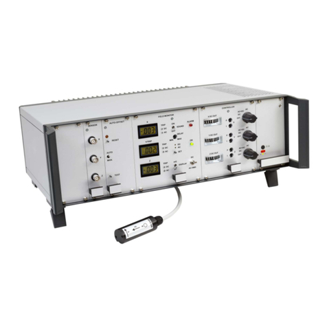
Stefan Mayer Instruments MK-1 User manual

Stefan Mayer Instruments
MK-1
Single Axis Magnetic Field
Compensation System
User’s Manual
valid for instruments with serial number 292 and higher
with auto-reset function
– January 2021 –
Stefan Mayer Instruments GmbH & Co. KG
Wallstr. 7, D-46535 Dinslaken, Germany
Tel./Fax: +49 2064 479762/3

Contents
1 Safety precautions 2
2 Introduction 3
3 Main frame with power supply and current source 4
3.1 Description ............................... 4
3.2 Specifications .............................. 5
4 Summing amplifier 5
5 Magnetometer 5
5.1 Description ............................... 5
5.2 Magnetometer specifications . . . . . . . . . . . . . . . . . . . . . . 6
6 Filter module 7
6.1 Description ............................... 7
6.2 Filter specifications . . . . . . . . . . . . . . . . . . . . . . . . . . . 7
7 Operation and adjustment 8
7.1 Gainadjustment ............................ 8
8 Conversion of Measurement Units 9
1

1 Safety precautions
The following safety precautions should be observed before using this
instrument:
This product is intended for use by qualified personnel who are familiar
with the safety precautions required to avoid possible injury.
Read the operating information carefully before using the instrument.
The instrument must not be operated in explosive atmosphere.
The instrument should only be used in dry rooms.
The operation of the instrument is left at user’s risk.
The instrument must be placed in such a way that it can be easily
disconnected from the power line by unplugging the mains plug.
The ventilation slots and heat sinks must not be covered. Provide suf-
ficient air flow for cooling. In critical cases an air fan should be used.
Before operating the instrument, make sure the power cord is connected
to a properly grounded power receptacle.
Before performing any maintenance, disconnect the power cord.
The detachable power cord must not be replaced with lower rating
types. See section 3.2 for power cord ratings.
Replace blown fuses with same type and rating for continued protection
against fire hazard.
Do not exceed the electrical and thermal operating limits, as defined
in the specifications section 3.2. Disregard can cause destruction of the
instrument and consequential damages.
If the instrument is used in a manner not specified by the manufacturer,
the protection provided by the instrument can be impaired.
Stefan Mayer Instruments shall not be liable for any direct, indirect,
special, incidental or consequential damages arising out of the use of its
instruments.
The instrument and this manual may be subject to alterations without prior notice.
2

2 Introduction
The MK-1 is a single axis magnetic field compensation system designed for image
improvement in magnetic resonance imaging (MRI) and other applications where
feedback magnetic field control systems are not suitable. The system reduces slow
disturbances, e. g. caused by trams, elevators or vehicles, as well as magnetic noise
produced by power lines by establishing a counteracting magnetic field with the
help of suitable compensation coils.
The magnetic field disturbances are measured with sensitive fluxgate magnetome-
ters in the frequency range from DC to 1 kHz. Sensitive DC magnetic field sen-
sors cannot be placed close to an MRI scanner due to its large DC magnetic
field. Therefore, the sensors are usually placed outside of the shielded MRI room,
whereas the compensation coils are installed inside the MRI room. The MK-1 is
a feed-forward controller with manually adjustable gain.
Figure 1: Operating principle of the compensation system MK-1.
The magnetometer signals are filtered, amplified, and added. The resulting signal
controls a current source for direct connection of compensation coils which generate
the counteracting magnetic field.
Maximum field attenuation is achieved by manual adjustment of the system gain.
The gain for slow signals up to 10 Hz and power line frequencies 50 Hz and 16.7
Hz (or 60 Hz, depending on version) can be separately adjusted. The phase of the
power line frequency signals is adjustable too.
The instrument consists of a 19 inch main frame unit with power supply, a current
3

source for direct connection of compensation coils, fluxgate magnetometers and
filter modules. The basic version contains one magnetometer and one filter module.
It is possible to install up to three magnetometers and filters. Compensation coils
are not part of the MK-1 and must be provided separately.
The mains power connector and switch as well as connectors for sensors and com-
pensation coils are located on the rear panel. The outer conductors of the BNC
connectors on the front panels are all connected with the case which is grounded.
This is important to know when connecting an external device like an oscilloscope.
In the following section the individual components of the instrument, their spec-
ifications and operation is explained. After that the setup and adjustments are
explained.
3 Main frame with power supply and current
source
3.1 Description
The main frame contains on the right side a power supply unit of type Kniel low
emission CA 15.4 with automatic input range switching. The power line receptacle
with power switch and two fuses is located on the rear panel. Further fuses are
inside the power supply unit. The input power is 150 W.
Caution: The instrument must not be powered with any voltage other
than 216 to 240 V or 108 to 120 V, 50 to 60 Hz AC. The line cord must
be properly grounded.
The current source for connection of compensation coils is located at the backside
of the instrument. The compensation coils must be connected to the removable
clamp connector COMPENSATION COILS near the backside heat sink. The
minimum allowed DC resistance of the connected compensation coils is 3.0 Ohms.
Caution: Because of the current source’s differential output any load
connected to compensation coils connector must be floating and must
not be grounded.
The ventilation slots and heat sink must not be covered. Provide suf-
ficient air flow for cooling during operation. In critical cases an air fan
should be used.
4

3.2 Specifications
Current source gain 0.5 A/V
Output current max. 2.5 A
Minimum load resistance ≥3.0 Ω
Compliance at 2.5 A typ. ±7 V
Power supply built in, 115/230 V ±10%,
AC 50 to 60 Hz, max. 2.0 A
Power cord ratings 250 VAC, 10A
Operating temperature 0 to 40 ◦C
Dimensions of main frame enclosure 19 inch, 3 HU, 310 mm depth
Weight 8 kg
4 Summing amplifier
The summing amplifier (module AMPLIFIER) is located near the power supply
unit. The magnetic field compensation system must not be operated without
amplifier module installed because the amplifier also provides the system’s analog
ground reference signal. The amplifier adds and amplifies the signals of up to three
magnetometer/filter modules. The amplifier’s gain can be adjusted in steps from
0 to 11. The LED bar graph display shows the DC drive level of the amplifier.
The display characteristic is non-linear. The amplifier output signal is fed to the
BNC connector OUT.
The amplifier module contains a window comparator which automatically resets
the magnetometers in case of an overrange condition, see section 5.1.
5 Magnetometer
5.1 Description
The measurement range of the fluxgate magnetometer is ±199.9 µT. The mea-
surement direction is axial, pointing away from the sensor cable. The sensor is
labeled with the serial number and a letter A, B, or C. It must be connected to
the corresponding receptacle SENSOR A, SENSOR B, or SENSOR C on the rear
5

panel. If two or three magnetometer modules are installed, then they must not be
interchanged.
The digital display shows the DC magnetic field in µT. The display range can
be changed between ±19.99 µT and ±199.9 µT with the switch RANGE. The
magnetometer is zeroed by pressing the RESET button. The actually measured
DC magnetic field component is subtracted from the magnetometer signal. This
procedure is indicated by the RESET LED and takes four seconds. After zeroing
the display shows a small value. The maximum field which can be zeroed is
±500 µT (5 Gauss). The magnetometer is automatically reset when the amplifier
detects an overrange condition, see section 4. The auto-reset function can be
deactivated by replacing a jumper on the amplifier board.
The analog output signal at the BNC connector has a bandwidth of 1 kHz (−3 dB).
The scale factor is 3 V/100 µT in range 199.9 µT (RANGE switch up) and
3 V/10 µT in range 19.99 µT (RANGE switch down). The scale factor of the
signal internally routed to the filter module does not depend on the range switch
position and is 3 V/100 µT.
5.2 Magnetometer specifications
Display 3.5 digits LED display with sign
Measurement range ±19.99 µT and ±199.9 µT
Resolution 10 nT
Noise <0.7 nT RMS
Accuracy 0.5% ±25 nT ±1 Digit
Operating temperature 0 to 40 ◦C
Max. field at sensor ±500 µT
Analog output 0.03 V/µT or 0.3 V/µT depending
on range switch position, short cir-
cuit protected, BNC connector
Output voltage range −6 to +6 V
DC output impedance 100 Ω
Bandwidth 0 to 1 kHz (–3 dB)
6

6 Filter module
6.1 Description
The filter module provides analog filtering of the magnetometer output signal. It
contains two parallel band-pass filter sections for 16.7 Hz (or 60 Hz, depending on
version) and 50 Hz, a DC channel, and a summing amplifier. The output signals
of the individual filter sections can be switched separately and with selectable
polarity to the input of the summing amplifier. The gain of the filter sections
can be adjusted between 1 and 11 with 10-turn potentiometers. The phase of the
band-pass filters is adjusted with the trimmers Φ.
The DC channel is filtered with a three pole 10 Hz Bessel low-pass filter. Jumper
settings can be changed on the filter board in order to change further parameters.
Figure 2: Jumper settings on the filter board
6.2 Filter specifications
Band-pass filter type Biquad active filter, 2nd order
Bandwidth (−3 dB) ∼2.6 Hz
Center frequency 16.7 Hz or 60 Hz and 50 Hz
Phase adjustment range −120 ◦to 0 ◦and −30 ◦to +90 ◦
Channel separation >20 dB
Operating temperature 0 to 40 ◦C
7

7 Operation and adjustment
Before the instrument is switched on with the rear side power switch, the sen-
sor(s) and compensation coils must be properly installed and connected to the
corresponding receptacles. Turn the rotary gain switch on the amplifier front to
position 0. When power is applied to the system, the digital displays and the
LEDs on the amplifier and power supply front turn on.
The magnetometers can be zeroed by pressing the RESET buttons.
7.1 Gain adjustment
Gain adjustment can be performed with the help of an external magnetometer
as follows: First, the external magnetometer must be put at a place inside the
compensation coils, where maximum compensation is required. Special induction
coil magnetometers are available for MRI applications. The induction coil is placed
at the isocentre of the MRI magnet. If more than one filter channel (DC, 16.7 Hz,
or 50 Hz) have to be activated it is recommended to start with the DC channel.
Activate a filter channel by switching the corresponding toggle switch to + or −.
Leave every channel activated while adjusting the next one. The 10-turn poten-
tiometers on the filter modules should be turned to approximate center position
(position 4 to 6). Then, the amplifier gain is increased by turning the rotary switch
on the amplifier panel clockwise until maximum field attenuation is achieved (when
the signal changes of the external magnetometer are minimum). If the signal does
not decrease with increasing gain, then reverse the polarity of the filter channel by
changing the corresponding toggle switch position and try again.
Finally, fine tuning of the gain is performed by changing the position of the filter
10-turn potentiometers and phase trimmers.
8

8 Conversion of Measurement Units
Magnetic induction B
Unit 1 Tesla (1 T)
1 T = 104Gauss = 1 kg s−2A−1
1µT = 10 mG
Magnetic field strength H
Unit 1 A/m
1 A/m = 4π×10−3Oersted
Connection between Band H
B=µ0Hfor non-magnetic environment
Vacuum permeability µ0= 4π×10−7m kg s−2A−2
Units:
1 A/m = 4π×0.1 µT / µ0'1.3 µT / µ0
1µT'0.8 A/m ×µ0
1µT = 10 mOe ×µ0.
9
Other manuals for MK-1
1
Table of contents
Other Stefan Mayer Instruments Measuring Instrument manuals
