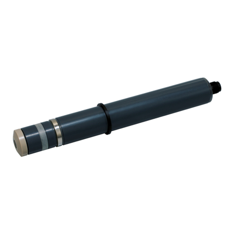
triOS VIPER User manual

VIPER
OPERATING INSTRUCTIONS


1
Product // Chapter
TABLE OF CONTENTS
Table of Contents
1 General Information 2
1.1 Introduction 2
1.2 Health and Safety Information 3
1.3 Warnings 4
1.4 Users and Operating Requirements 4
1.5 Intended Use 5
1.6 Disposal Information 5
1.7 Certicates and Approvals 5
2 Introduction 6
2.1 Calibration sets 6
2.1.1 DIN EN ISO 7887:2012-04 6
2.1.2 DIN EN ISO 6271:2016-05_APHA /
Hazen_Pt-Co color 6
2.1.3 GOST 3351-74_Cr-Co color 7
2.2 Product Identication 7
2.3 Scope of Delivery 7
2.4 Measurement Principle and Design 8
2.4.1 Spectra Calculation 9
2.4.2 Calculation of the Parameters 9
2.4.3 Temperature Correction 10
2.5 Parameters and Measuring Ranges 10
2.6 Browser 11
3 Commissioning 20
3.1 Electrical Installation 20
3.1.1 SubConn 8-pin Connector 20
3.1.2 Fixed Cable with M12 Industrial Plug 21
3.2 Interfaces 22
3.2.1 Digital Interfaces 22
3.2.2 Network 23
4 Use 26
4.1 Normal Operation 26
4.1.1 Immersion Operation 26
4.1.2 Cleaning System 27
4.1.3 Float 29
4.2 Bypass 29
4.3 Use with a Cuvette 31
5 Calibration 32
5.1 Factory Calibration 32
5.2 Water Base 32
5.3 Customer Calibration 33
5.4 Measurement Properties 35
6 Malfunction and Maintenance 36
6.1 Cleaning and Upkeep 36
6.1.1 Cleaning the Housing 36
6.1.2 Cleaning the Measuring Window 37
6.1.3 Preparing the Sensor for the Function Test
and Zero Value Determination 37
6.2 Maintenance and Inspection 38
6.2.1 Checking the Zero Value 38
6.3 Troubleshooting 40
6.3.1 Uploading Recovery Point 40
6.3.2 Firmware Updates 40
6.4 Returns 40
7 Technical Data 41
7.1 Technical Specications 41
7.3 External Dimensions 43
8 Accessories 44
8.1 Controller 44
8.1.1 TriBox3 44
8.1.2 TriBox mini 44
8.2 Compressed air ttings for 100-250 mm paths 44
8.3 VALtub 44
9 Warranty 45
10 Customer Service 46
11 Contact 47
12 Keyword Index 48
13 FAQ - Frequently Asked Questions 50
Annex 52

2D01-043en202112 Manual VIPER
Use Calibration Malfunction &
Maintenance
Commis-
sioning
Introduction FAQTechnical Data Warranty Customer
Service Contact Keyword
Index
Accessories
General
Information
General Information // VIPER
1 General Information
1.1 Introduction
Welcome to TriOS.
We are glad that you have chosen to purchase our VIPER photospectrometer.
VIPER is a submersible VIS process spectrophotometer, that is designed for use in industry and science. It may
only be used for measuring aqueous solutions, e.g. process wastewater, river water, groundwater and seawater
in a temperature range from 2 to 40 °C.
The sensor VIPER and all accessories supplied by TriOS Mess- und Datentechnik GmbH must be installed
and operated in accordance with the specications from TriOS Mess- und Datentechnik GmbH. All parts have
been designed and tested according to international rules for electronic instruments. The device complies with
applicable international rules on electromagnetic compatibility.
Please use only original accessories and cables from TriOS Mess- und Datentechnik GmbH for a smooth and
professional use of the devices.
The safety precautions noted on the following pages are intended to provide a simple and correct operation of
the instrument and all its accessories to prevent harm from coming to you, other people or devices.
Please read this manual carefully before using the equipment and save it for future reference.
Make sure that you have read and understood the safety precautions described below before using the sensor.
Always make sure that the sensor is operated correctly.
Please note that the user is responsible for compliance with local and state regulations for the installation of
electronic equipment. Any damage caused by improper use or unprofessional installation is not covered by the
warranty.
Copyright notice
All of the content in this manual, including texts, photographs and graphics, are protected by copyright. Unless
expressly stated otherwise, TriOS Mess- und Datentechnik GmbH is the owner of the copyright. Violations of
this copyright will be punishable according to section 106 of the German Copyright Act. The violator will be
warned at his own expense and must pay compensation.
Should translations dier from the original German text, then the German version
is binding.
Software Updates
The gures used in this manual refer to software version 1.0.2 or higher. Updates include bug xes, new fea-
tures and options. Devices with older software versions may vary from this manual version.
NOTICE

3D01-043en202112 Manual VIPER
UseCalibration
Malfunction &
Maintenance
Commis-
sioning IntroductionFAQ Technical DataWarranty
Customer
Service
Contact
Keyword
Index Accessories General
Information
VIPER // General Information
Never look directly into the light source without suitable UV protection! The
UV light can irreversibly damage your eyes.
1.2 Health and Safety Information
This manual contains important information about health and safety rules. This information is labelled according
to the international specications of ANSI Z535.6 (“Product safety information in product manuals, instructions
and other collateral materials”) and must be followed strictly. The distinction is made between the following
categories:
Electromagnetic waves
Devices that radiate strong electromagnetic waves can inuence the measurement data or result in a malfunc-
tion of the sensor. Avoid using the following devices in the same room as the TriOS sensor: mobile phones,
cordless phones, transmitters/receivers and other electrical devices that produce electromagnetic waves.
Reagents
Follow the safety and operating instructions of the manufacturer when using reagents. Observe the valid Haz-
ardous Materials Ordinance for reagents (German GefStoV).
Biological safety
Liquid waste may be a biohazard. Therefore, you should always wear gloves when working with such materials.
Please observe the current biological material ordinance (German BioStoV).
Waste
When handling liquid waste, observe the regulations on water pollution, drainage and waste disposal.
Tip / Useful Information
Can result in damage to property
Warning / may lead to serious injury or death
Caution / may cause moderate injury
Danger warning / will lead to serious injury or death
DANGER
WARNING
CAUTION
NOTICE
CAUTION

4D01-043en202112 Manual VIPER
Use Calibration Malfunction &
Maintenance
Commis-
sioning
Introduction FAQTechnical Data Warranty Customer
Service Contact Keyword
Index
Accessories
General
Information
General Information // VIPER
1.3 Warnings
• This sensor is designed for use in industry and science. It may only be used for the measuring of aqueous
solutions, e.g. process wastewater, river water, groundwater or seawater.
• Sensors made of stainless steel must be cleaned immediately after contact with salt water or other sub-
stances that cause corrosion (e.g. acids, alkalis, chlorine-based compounds). The material resistance
should be tested for each application.
• VIPER has NBR (nitrile butadiene rubber) seals. Sealing rings made from other materials may be used
upon individual request. Before operation, please ensure that the measured medium does not damage
the seals.
• Do not cut, damage or change the cord. Make sure that no heavy objects are placed on the cord and that
the cord is not folded. Make sure that the cord is not run near hot surfaces.
• If the sensor cable is damaged, it must be replaced with an original part by the customer support of TriOS
Mess- und Datentechnik GmbH.
• Do not place unsuitable items in the optical path when the measurement process is in operation, because
this can cause damage to the sensor or incorrect measurement results.
• Stop operation of the sensor if excessive heat develops (i.e., if it is hot to the touch). Switch o the sen-
sor immediately and unplug the power cord from the power supply. Please contact your dealer or TriOS
technical support.
• Never try to disassemble or modify a part of the sensor if such a procedure is not explicitly described in
this manual. Inspections, modications and repairs may only be done by the dealer or by qualied experts
authorized by TriOS.
• Devices from TriOS Mess- und Datentechnik GmbH meet the highest safety standards. Repairs to the
device (that involve the replacement of the connecting cable) must be carried out by TriOS Mess- und
Datentechnik GmbH or a workshop authorized by TriOS. Faulty, improper repairs can result in accidents
and injuries.
1.4 Users and Operating Requirements
The VIPER photometer has been developed for use in industry and science. The target group for the operation
of VIPER probe is technically skilled sta in plants, sewage treatment plants, water plants and institutes. The
use of this device often requires the handling of hazardous substances. We assume that the operating person-
nel are familiar with dealing with dangerous substances based on their professional training and experience.
The operating personnel must be able to correctly understand and implement the safety labels and information
on the packaging and in the package inserts of the test kits.
Sensors made of stainless steel are not made for use in seawater or high chloride
concentrations (corrosion). Only sensors made of titanium can be used here.
TriOS does not guarantee the plausibility of the measured values. The user is
always responsible for monitoring and interpreting the measured values.
NOTICE
NOTICE

5D01-043en202112 Manual VIPER
UseCalibration
Malfunction &
Maintenance
Commis-
sioning IntroductionFAQ Technical DataWarranty
Customer
Service
Contact
Keyword
Index Accessories General
Information
VIPER // General Information
1.5 Intended use
The intended use of VIPER consists solely in recording absorbance spectra in the visible range and carrying
out photometric measurements at specic wavelengths as described in this manual. In this respect, VIPER is
a submersible sensor which can be submerged or used with a ow cell. Observe the technical specications of
the accessories. Any other use is considered improper.
This sensor is designed for use in science and industry. Use this sensor exclusively for measuring the absorb-
ance of aqueous liquids. The use in other media may result in damage to the sensor. Should you wish to use
VIPER in media other than the specied, please contact the technical support of TriOS Mess- und Datentechnik
GmbH ([email protected]).
According to current scientic knowledge, the device is safe to use if handled properly and according to the
instructions in this manual.
1.6 Disposal Instructions
At the end of the device’s life or use, the device and its accessories can be returned to the manufacturer for
environmentally friendly disposal for a fee (see address below). The preceding professional decontamination
of the device must be proven with a certicate. Please contact us before you send the device back to get more
details.
Address of the manufacturer:
TriOS Mess- und Datentechnik GmbH
Bürgermeister-Brötje-Str. 25
26180 Rastede
Germany
Phone: +49 (0) 4402 69670 - 0
Fax: +49 (0) 4402 69670 - 20
1.7 Certicates and Approvals
This product meets all of the requirements of the harmonized European standards. It therefore meets the legal
requirements of the EU guidelines. TriOS Mess- und Datentechnik GmbH conrms the successful testing of the
product by axing the CE marking. (See annex).
Avoid any unnecessary contact with the glass parts in the optical path, as they can
become scratched or dirty. This means that the functionality of the device is no
longer guaranteed.
Damage caused by improper use is excluded from the warranty.
NOTICE
NOTICE

6D01-043en202112 Manual VIPER
Use Calibration Malfunction &
Maintenance
Commis-
sioning
General
Information FAQTechnical Data Warranty Customer
Service Contact Keyword
Index
AccessoriesIntroduction
Introduction // VIPER
2 Introduction
VIPER is an independent measuring instrument that can be operated with a 12–24 VDC power supply.
It is equipped with a congurable serial interface that supports RS-232 and RS-485 standards as well as the
protocol Modbus RTU. This makes the sensor particularly suitable for complex, PLC-controlled industrial sys-
tems, as well as for long-term research purposes.
A built-in Ethernet interface also enables sensor conguration via various web browsers. Users may assign
osets and scaling factors to measurements, congure serial interfaces and other sensor related settings. Refer
to the corresponding chapter of this manual for further information.
Like all TriOS Mess- und Datentechnik GmbH sensors, VIPER is delivered pre-calibrated so that it is ready for
immediate use.
This manual provides information about the specications, the installation and the operation of the sensor
VIPER.
2.1 Calibration Sets
2.1.1 DIN EN ISO 7887:2012-04
The norm DIN EN ISO 7887:2012-04 describes the “Examination and determination of color”.
Method B species the determination of the true color of a water sample using an optical instrument. The deter-
mination wavelengths are 436, 525 und 620 nm. The method is applicable to raw and potable water and lightly
colored industrial wastewater.
Method C describes the determination of true color using optical instruments for the determination of absorb-
ance at a wavelength of 410 nm. The color solution for calibration consists of potassium hexachloroplatinate
and cobalt chloride.
VIPER measures color at 410 nm as well as SAC 436, SAC 525 and SAC 620 direct in the medium. A ltration
of the water is not necessary because the absorbance at a wavelength of 720 nm is used for turbidity correction.
2.1.2 DIN EN ISO 6271:2016-05_APHA / Hazen_Pt-Co color
DIN EN ISO 6271:2016-05 species a spectrophotometric method for estimating the color of clear liquids by
the platinum-cobalt color scale. It is applicable to clear liquids having color characteristics similar to those of the
reference platinum-cobalt scale.
The term “platinum-cobalt color” used in the norm is preferred over the terms “Hazen color” and “APHA color”.
The Pt-Co scale is dened as a classication of the color of a solution containing platinum, in the form of the
hexachloroplatinate(IV) ion, and cobalt(II) chloride hexahydrate in specied concentrations.
The recommended path length is 50 mm. The measuring range is 0 to 500 Pt-Co color.
VIPER measures color at 390 nm or 455 nm direct in the medium. A ltration of the water is not necessary
because the absorbance at a wavelength of 720 nm is used for the turbidity correction.

7D01-043en202112 Manual VIPER
UseCalibration
Malfunction &
Maintenance
Commis-
sioning
General
Information
FAQ Technical DataWarranty
Customer
Service
Contact
Keyword
Index Accessories Introduction
VIPER // Introduction
2.2 Product Identication
All TriOS Mess- und Datentechnik GmbH products have a label, which clearly shows the product designation.
There is also a rating plate on the sensor with the following information that you can use to uniquely identify
the product:
2.3 Scope of Delivery
The shipment contains the following components:
• Sensor
• Manual
• Accessories (if applicable)
Keep the original device packaging in case the device needs to be returned for maintenance or repairs.
Serial number
Product type
Power supply
Interface
In addition to the product bar code, the rating plate includes the TriOS Mess- und Datentechnik GmbH logo and
the quality label.
Please note that the specications given here are for illustration purposes only and may be dierent depending
on the version of the product.
2.1.3 GOST 3351-74_Cr-Co color
The USSR National Standard Method „GOST 3351-74” describes a photometric method to evaluate the pres-
ence of color in drinking water. The colorimetric scale is prepared with a mixture of potassium dichromate and
cobalt sulfate in diluted sulfuric acid. It is dened form 0 to 70 color degrees. The evaluation of color with a
photoelectric colorimeter is done using path lengths of 50 to 100 mm. The optical density of the ltrate of the
water sample is measured in the blue part of the spectrum at 413 nm.
VIPER measures color at 413 nm directly in the medium. A ltration of the water is not necessary because the
absorbance at a wavelength of 720 nm is used for the turbidity correction.

8D01-043en202112 Manual VIPER
Use Calibration Malfunction &
Maintenance
Commis-
sioning
General
Information FAQTechnical Data Warranty Customer
Service Contact Keyword
Index
AccessoriesIntroduction
Introduction // VIPER
2.4 Measurement Principle and Design
For the optimal use of the sensor, it is recommended to become familiar with the idea and theory underlying the
device, as well as with its assembly procedure.
VIPER consists of four parts: a dened light source, a lens system, the optical path through the medium, and
a spectrometer.
The light source consists of 5 LEDs. The emitted light is focused to a parallel beam passing the measurement
medium. A second lens with a small focal length focuses the beam at the inlet slit of the miniature spectrometer.
The emitted light is partially absorbed and scattered by molecules and particles during passage through the
medium. The spectrometer picks up the remaining, spectrally resolved light and determines its intensity Iat dif-
ferent wavelengths over a dened wavelength range. A measurement in ultrapure water provides the so-called
base-intensity I0. This is the light intensity that reaches the spectometer after passage through the pure meas-
uring medium which contains only solvent molecules and no other components like determinants and particles.
The remaining light intensity I is divided by the base-intensity I0to calculate transmission T (see Equation 1). Ac-
cording to Equation 2 the absorbance A is calculated for each wavelength over the dened wavelength range.
T=
Equation 1: Calculation of transmission
I
I0
Light Source Reference Diode Optical Path Spectrometer
A= -log10T T= -log10
Equation 2: Calculation of absorption
Each sensor is delivered with a water basis as zero line. It is measured in ultra pure water following our internal
calibration standards.
I
I0

9D01-043en202112 Manual VIPER
UseCalibration
Malfunction &
Maintenance
Commis-
sioning
General
Information
FAQ Technical DataWarranty
Customer
Service
Contact
Keyword
Index Accessories Introduction
VIPER // Introduction
2.4.1 Spectra Calculation
Every measurement of VIPER consists of a light and a dark measurement. During the light measurement the
LEDs emit their light, which is detected with the spectrometer as a light spectrum (= raw light). During the dark
measurement the LEDs are o. The detected spectrum (= raw dark) is caused only by electronic noise. The
dark values are approximately constant over the whole wavelength range and depend slightly on the measuring
temperature and the integration time (IT).
The time during which the spectrometer collects the light photons is called the integration time (IT). The max-
imum value of a single spectrometer photodiode is approx. 65000 counts. If the light intensity at a certain
wavelength is too high, the IT is lowered.
The raw dark spectrum is subtracted from the raw light spectrum. The remaining values are calculated with the
IT and a temperature correction factor. The result is a calibrated spectrum.
The reference for the calculation of absorbance is usually a measurement in ultra pure water. The calibrated
spectrum of the ultra pure water measurement is called the zero line or waterbase. The intensity of each wave-
length is the so-called base-intensity I0. According to Equation 2 absorbance for each wavelength is caculated.
The received spectrum is the absorbance spectrum. The unit of the absorbance value is AU which stands for
absorbance unit.
The absorbance values should not exceed 2.5 AU. If this is the case, the concen-
tration of the determinants or the particle fraction in the measurement medium is
too high for the selected path length. The path length must be shortened to obtain
qualitative measurements and measured values.
2.4.2 Calculation of the Parameters
Every VIPER is equipped with a pre-dened parameter set (see table in chapter 5.1)
Under consideration of the pathlength, absorbance values [AU] at specic wavelengths are calculated to ab-
sorbance values with the unit [1/m].
The calculation of the spectral absorption coecient (SAC) is described below:
VIPER uses absorbance at a wavelength of 720 nm (A720) for turbidity correction of absorbance (AWL, meas-
ured at a specic wavelength). The SAC at the specic wavelength (SACWL) is calculated as shown in Equation
3. In this equation d is the optical path length in millimeter [mm]. For VIPER, optical path lengths of 50 mm, 100
mm, 150 mm and 250 mm are available.
SAC
WL = [1/m]
Equation 3: Spectral absorption coecient at a specic wavelength (WL).
(AWL - A720) ∙1000
d
NOTICE

10 D01-043en202112 Manual VIPER
Use Calibration Malfunction &
Maintenance
Commis-
sioning
General
Information FAQTechnical Data Warranty Customer
Service Contact Keyword
Index
AccessoriesIntroduction
Introduction // VIPER
2.4.3 Temperature Correction
The light intensity of LEDs often varies with temperature. Therefore, a temperature correction factor is deter-
mined for each wavelength of the VIPER spectrum and used for the spectrum calculation.
2.5 Parameter and Measuring Ranges
The following table provides an overview of the measurement ranges of the detectable parameters in depend-
ence on the path length. Some applications are working with a factor to scale the SAC (spectral absorption
coecient) at a certain wavelength into a special parameter.
The transmission at 720 nm may not fall below 33 %, otherwise the content of
suspended solids in the medium is too high and the measuring range for the
parameters could be exceeded. 33 % transmission corresponds to an absorbance
value of 0.5 AU.
VIPER measuring ranges in dependence on the path length*.
Parameter
according to Unit Factor Path Length (mm)
10 50 100 150 250
SAC436
DIN EN ISO
7887: 2012-04 1/m - 1...250 0.2...50 0.1...25 0.06...17 0.04...10
SAC525
DIN EN ISO
7887: 2012-04 1/m - 1...250 0.2...50 0.1...25 0.06...17 0.04...10
SAC620
DIN EN ISO
7887: 2012-04 1/m - 1...250 0.2...50 0.1...25 0.06...17 0.04...10
True Colour 410 DIN EN ISO
7887: 2012-04 mg/L Pt 18.52 20...3750 4...750 2...375 1.2...250 0.8...150
Pt-Co colour 390 DIN EN ISO
6271:2016-05 mg/L Pt 7.4 8...1500 1.6...300 0.8...150 0.4...100 0.2...60
Pt-Co colour 455 DIN EN ISO
6271:2016-05 mg/L Pt 36.4 40...7500 8...1500 4...750 2.4...500 1.4...300
Cr-Co colour 380 - ° (degree of
colour) 9.7 10.0...2000 2...400 1...200 0.6...130 0.4...80
Cr-Co colour 413 Gost 3351-74 ° (degree of
colour) 34.1 40...7000 8...1400 4...700 2.6...450 1.6...275
* under laboratory conditions
NOTICE

11D01-043en202112 Manual VIPER
UseCalibration
Malfunction &
Maintenance
Commis-
sioning
General
Information
FAQ Technical DataWarranty
Customer
Service
Contact
Keyword
Index Accessories Introduction
VIPER // Introduction
2.6 Browser
VIPER is equipped with a web interface for sensor conguration and calibration. To access the web interface,
you need a G2 InterfaceBox, an Ethernet cable and an Ethernet-enabled device with a web browser, e.g. a
notebook / laptop.
Open one of the following URLs (depending on the network structure) in your web browser:
http://VIPER/
http:// VIPER _AXXX / (AXXX represents the serial number)
http://192.168.77.1/
When an Ethernet-enabled device is connected, the automatic measurements are suspended.
As soon as the sensor is disconnected from your device again, the measurements will contin-
ue at the set interval if the timer for automatic measurements is activated.
The web interface is divided into three areas:
Title (above), menu (to the left under the TriOS logo) and content (right).
Menu
Title
Content
Under the menu, there is a login section only accessible to certied TriOS Mess- und Datentechnik GmbH
service technicians.
In the menu on the left, the subpoints are listed. There is a “Help” link on the right side that will take you to the
TriOS Mess- und Datentechnik GmbH website. An active internet connection is required to access the website.
The following gures are examples for VIPER True color according to DIN EN ISO 7887:2012-04. The other
calibration sets vary in details.

12 D01-043en202112 Manual VIPER
Use Calibration Malfunction &
Maintenance
Commis-
sioning
General
Information FAQTechnical Data Warranty Customer
Service Contact Keyword
Index
AccessoriesIntroduction
Introduction // VIPER
The menu is used to navigate the web interface. Each line is a link to another page with dierent setting options.
The link that refers to the page that is currently displayed is always highlighted in the menu. Some of the con-
tents and functions are reserved for the employees of TriOS Mess- und Datentechnik GmbH Customer Service.
Authentication is needed to access this content. This content is not accessible to every user.
The contents area displays the relevant information and setting options. Content that requires authentication is
disabled (“grayed out”) if authentication fails or is not possible due to lack of appropriate information.
If settings have been made, they must be saved with the “Save” button. Other-
wise the settings will be lost again.
Overview
The “Overview” page summarises basic information about VIPER. This includes device type, serial number and
rmware of the sensor at the top, and lamp type, lamp serial number and shot counter (number of light ashes)
at the bottom.

13D01-043en202112 Manual VIPER
UseCalibration
Malfunction &
Maintenance
Commis-
sioning
General
Information
FAQ Technical DataWarranty
Customer
Service
Contact
Keyword
Index Accessories Introduction
VIPER // Introduction
Data logger
VIPER is equipped with an internal data logger with a data memory of 2 GB. This allows an almost completely
self-sucient operation over a very long period. The only accessory required is an appropriately dimensioned
power supply. The following gure shows the layout of the page “Data Logger”
Calibration
Lamp spectrum (I0) is displayed on the “Calibration” page under “Waterbase”. The setting of the optical path in
millimetres is displayed in “Settings”.

14 D01-043en202112 Manual VIPER
Use Calibration Malfunction &
Maintenance
Commis-
sioning
General
Information FAQTechnical Data Warranty Customer
Service Contact Keyword
Index
AccessoriesIntroduction
Introduction // VIPER
Status
The status indicates the memory percentage which is still available.
The “Clear” button formats the memory and deletes all data - for safety only after conrming the security prompt.
Download
Previously stored data can be retrieved with the “Download” button. It is possible to set a start and an end
date for the data download. We recommend choosing a window of time for the download / export, because the
download of approximately 2 GB can take a long time.
Settings
VIPER stores and outputs data in the le formats CSV (Comma Separated Values) and the dat. format. CSV
les can be opened in the most common spreadsheet programs. The default conguration is “TriOS Standard”.
In this case, numerical values are saved in CSV format and spectra are saved in .dat format. However, you can
change this setting and save both in CSV format.
After conrming the security prompt, the memory on the VIPER and thus all data is irrevoca-
bly deleted.

15D01-043en202112 Manual VIPER
UseCalibration
Malfunction &
Maintenance
Commis-
sioning
General
Information
FAQ Technical DataWarranty
Customer
Service
Contact
Keyword
Index Accessories Introduction
VIPER // Introduction
Measurement
The “Measurement” page shows the results of the last performed measurement and allows conguring the
settings for automatic measurements.
Parameter
A new measurement can be triggered at any time. To do this, click on the “Measure Now!” button. A new meas-
urement will then be performed with the saved settings.
The results calculated at the last measurement are listed. “Edit” allows to scale the measured values with
“Oset” and “Scaling”.
The formula used to calculate the scaled measured value with scaling factor and oset is shown in the top row.
(Raw Value - Oset) x Scaling = Scaled Value
(Measured value - axis shift) x scaling factor = scaled measured value
The possibility to scale parameters is given for every parameter that is calculat-
ed by a TriOS Mess- und Datentechnik GmbH probe. Parameters should only be
scaled, if a reference measurement of the medium concerning the parameter is
available.
NOTICE

16 D01-043en202112 Manual VIPER
Use Calibration Malfunction &
Maintenance
Commis-
sioning
General
Information FAQTechnical Data Warranty Customer
Service Contact Keyword
Index
AccessoriesIntroduction
Introduction // VIPER
Spectrum
The “Spectrum” item shows the measured absorption spectrum. Press the “Download” button to download/copy
this spectrum to the computer as a CSV le.
Settings
In the subitem “Settings”, settings for the automatic measurement can be made after pressing the “Edit” button:
• Comments entered in the “Comment” eld can be linked to measured values and spectra.
• Automatic measurements can be activated.
• An interval for the automatic measurements can be specied.

17D01-043en202112 Manual VIPER
UseCalibration
Malfunction &
Maintenance
Commis-
sioning
General
Information
FAQ Technical DataWarranty
Customer
Service
Contact
Keyword
Index Accessories Introduction
VIPER // Introduction
Peripherals
The “Peripherals” page is used to congure the interface, select a protocol, and change the Modbus address.
To do so, just click on the “Edit” button at the page bottom.
The factory settings are:
Hardware mode: RS-485
Protocol: Modbus RTU
Baud rate: 9600
Flow control: None
Parity: None
Data bits: 8
Stop bits: 1

18 D01-043en202112 Manual VIPER
Use Calibration Malfunction &
Maintenance
Commis-
sioning
General
Information FAQTechnical Data Warranty Customer
Service Contact Keyword
Index
AccessoriesIntroduction
Introduction // VIPER
System
The “System” page is used for general VIPER congurations. Users can load a calibration le and download
the current calibration as a recovery point.
Common Settings
After pressing the “Edit” button, a comment such as a name or the location of the sensor can be entered here.
This then appears in the “Overview” menu.
Current Date and Time
Here the date and time of the sensor can be set manually or synchronized with the PC.
Recovery Point
Click on the “Download” button to download the latest sensor calibration to a PC or other support. This calibra-
tion le (cong.ini) must be stored and kept safe. For the normal user this le is encrypted and unreadable to
avoid unauthorized changes.
Use the “Upload” function to restore a previously downloaded calibration le or to upload a calibration le gen-
erated by the technical support of TriOS Mess- und Datentechnik GmbH. If the operation is successful, this will
be indicated by a green box that reads “Success”. Otherwise, you should see a box with an error message at
Table of contents
Other triOS Measuring Instrument manuals
Popular Measuring Instrument manuals by other brands

Chauvin Arnoux
Chauvin Arnoux 6503 user manual

HB Ross Manufacturing Co.
HB Ross Manufacturing Co. ACVGD ROSS METER user manual

CAS
CAS CAS-X320 Reference manual

Bühler technologies
Bühler technologies GAS 222.20 Installation and operation instructions
Simpson
Simpson 390-2 instruction manual
TES
TES TES-1358 instruction manual
